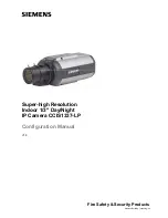
background image

Fire Safety & Security Products

Siemens Building Technologies


Super-high Resolution 
Indoor 1/3" Day/Night  
IP Camera CCIS1337-LP 

Configuration Manual 

V1.0 

Summary of Contents for CCIS1337-LP

Page 1: ...Fire Safety Security Products Siemens Building Technologies Super high Resolution Indoor 1 3 Day Night IP Camera CCIS1337 LP Configuration Manual V1 0 ...

Page 2: ...thereof in full or in part nor to make them available to any third party without our prior express written authorization nor to use it for any purpose other than for which it was delivered to him Contact We hope that you will enjoy success in applications involving this product If you have any questions your local SIEMENS representatives will be pleased to assist you Copyrights Copyright 2006 Fire...

Page 3: ...3 Siemens Building Technologies Fire Safety Security Products 04 2006 About this document This user guide explains the installation and configuration of the IP camera ...

Page 4: ...up 22 8 1 Setting up the IP camera 22 8 1 1 Setting the focal length 23 9 Operational setup 24 9 1 Establishing initial communication with the unit 24 9 1 1 Changing the IP address of the client PC 24 9 1 2 Mapping a network route 25 9 2 Checking device accessibility 25 10 Configuration 26 10 1 Establishing access to the device via Internet 26 10 1 1 Example of access using a dynamic IP address 27...

Page 5: ...restart 46 10 8 2 Time controlled restart 47 10 8 3 Restart by Ping Watchdog 47 10 9 Live video 48 10 9 1 Displaying live video 48 10 9 2 Setting live video resolution 50 10 9 3 Saving still pictures 50 10 10 Embedding live video images in a dedicated HTML page 51 10 10 1 Live video in Gecko based browsers 51 10 10 2 Live video with Internet Explorer 52 10 10 3 Incorporating a still image in an HT...

Page 6: ......

Page 7: ... IP camera enables lives images to be shown over a network on a PC The live images can be transmitted via a TCP IP based network and viewed with a Web browser such as Netscape V7 0 Mozilla 7 0 or Internet Explorer version 5 5 or later Image parameters and network settings of the IP camera can be configured over the network ...

Page 8: ...ude this document z Installation operational start up configuration and repairs should only be performed by qualified personnel See Section 2 2 Target Group z Burn hazard Do not touch the housing of the unit while it is in operation z Overheating hazard During installation and operation ensure that there is sufficient air circulation for the IP camera to prevent heat build up Do not use the IP cam...

Page 9: ...signal words Ignoring these hazards may lead to the consequences indicated Signal word Type of hazard WARNING Possible danger of death or severe bodily harm CAUTION Danger of minor bodily injury or property damage IMPORTANT Danger of malfunctions 2 5 Meaning of the hazard symbols The nature of the hazard is indicated by icons Dangerous situation Electrical voltage ...

Page 10: ...electromagnetic compatibility The EU declaration of conformity is available from Siemens Building Technologies Fire Security Products GmbH Co oHG 76181 Karlsruhe Germany EU Directive 89 336 EEC on electromagnetic compatibility Conformity with the EU Directive 89 336 EEC is demonstrated by compliance with the following standards Emitted interference EN 61000 6 3 EN 55022 Resistance to interference ...

Page 11: ... 0 Vpp 75 Ω BNC Y C Y 1 0 Vpp C 0 3 Vpp 75 Ω 4 pin mini DIN Lens jack CS mount Horizontal resolution Color 540 lines B W 570 lines with Y C output Gamma correction 0 45 1 Minimum illumination Color 0 4 lux at F 1 4 AGC 30 dB 50 video B W 0 08 lux at F 1 4 AGC 30 dB 50 video Signal to noise ratio 50 dB Exposure system Automatic 1 50 1 100000 sec max 9 manual settings 1 50 1 120 1 250 1 500 1 1000 1...

Page 12: ...n IP address configurable via ARP BOOTP DHCP connection to twisted pair RJ 45 Ethernet Network connection 10BaseT Ethernet or 100BaseTX Fast Ethernet auto sensing full half duplex Image formats QCIF 176x144 25 ips CIF 352x288 25 ips 4CIF 704x576 10 ips interlaced Image transmission Motion JPEG multipart x mixed replace content type user configurable JPEG single image frame quality streaming up to ...

Page 13: ...gh resolution day night indoor IP camera MJPEG PAL 540 lines 12 V DC 24 V AC 50 Hz or PoE 0 50 kg Extra accessories not included in the standard delivery CAPA2415 C230 2GF1800 8BK Compact power supplyl 230 24 V AC 2 5 A 1 9 kg NOTE The 12 V power supply order no 2GF1800 8BE found in the product range is not suited for use with this IP camera because it does not provide enough power ...

Page 14: ...ng Technologies Fire Safety Security Products 04 2006 6 Package contents z Super high resolution indoor 1 3 day night IP camera CCIS1337 LP z C CS mounting adapter z Quick installation guide z CD with operating manual z CD with software ...

Page 15: ...nnection for external control alarm color BW 6 Lens type selection Video DC 7 Power connection 8 Lens jack 9 BNC jack for video output 10 RJ 45 network connection 11 Mini DIN connection for Y C video output 12 GND connection shielded 13 12 V DC 24 V AC connection 14 12 V DC 24 V AC connection 15 Connection for external control GND 16 Connection for external control B W 17 Connection for external c...

Page 16: ...ctor socket definition IRIS pin assignment Video lens DC lens 1 12 V 1 Damp 2 NC 2 Damp 3 VIDEO 3 Drive 4 GND 4 Drive 1 2 3 4 Y C output 1 GND 2 GND 3 Y luminance 1 Veff 75 Ω 4 C chrominance 0 3 Veff burst 75 Ω 1 2 4 3 RJ 45 network connection 1 TX 2 TX 3 RX 4 DC 5 DC 6 RX 7 DC 8 DC 7 6 5 4 3 2 1 8 ...

Page 17: ...Unit description 17 Siemens Building Technologies Fire Safety Security Products 04 2006 7 3 System connections Fig 1 System connections ...

Page 18: ...m with the Enter key Î The unit s home page will be displayed 7 4 2 Accessing the unit s home page with the Web Cam IP Manager This assumes that The Web Cam IP Manager and all the units are located in the same network segment If a device and the Web Cam IP Manager are not located in the same network segment you must ensure that associated gateway router passes the SSDP multicast messages sent by t...

Page 19: ...l now display a list of all the devices available for communication along with their IP and MAC addresses Each device s IP address or MAC address is unique 3 Select the device whose home page you want to access 4 Click the Home page of selected server button Î The home page of the selected device will appear See Section 7 5 Components of the unit home page ...

Page 20: ...anguage selection list box Standard setting English 2 Main menus 3 PTZ operating panel see Section 7 5 1 PTZ control for more information 4 Display area for live video images See Section 10 9 1 Displaying live video for more information 5 Buttons for displaying live video images See Section 10 9 1 Displaying live video for more information 6 Submenu ...

Page 21: ...tion number To input two digit position numbers click the button first 4 Save position The current pan tilt position is stored under the selected position number point 6 Up to 64 positions can be stored for the SIEMENS PTZ the SIEMENS CCDA can store up to 55 positions 5 Focus adjustment The focus can be set here The button sets the focus for distant objects the ο button is for focusing on objects ...

Page 22: ...he unit 1 Ensure that there is sufficient air circulation for cooling 2 Do not operate the IP camera in its protective housing 3 Connect the power supply IP camera with separate power supply Connect the power supply to the power supply connection 7 IP camera with network connection 10 Ensure that the network equipment such as the switch hub router supports Power Over Ethernet POE CAUTION Ensure th...

Page 23: ...etting the focal length 1 Loosen the back focus lock screw 2 2 Set the IP camera to the back focus operating mode See Section 10 5 7 Service configuration Î The lens aperture opens completely 3 Turn the back focus dial 1 until the image is in focus 4 Tighten the screw 2 again carefully 5 Connect the IP camera to the network using a network cable connected to the RJ 45 network jack 10 ...

Page 24: ...the client PC NOTE You must change the network settings of your client PC temporarily in order to perform the following steps Therefore you should write down the original IP address and original subnet mask setting of your client PC 1 Open the network connections via the Windows Start Menu Start Settings Control panel Network connections 2 Right click on the chosen connection and select Properties...

Page 25: ...12 13 3 Type route add 192 168 100 0 mask 255 255 255 0 10 11 12 13 and press the Enter key Î A network route will be established that ensures device accessibility Note that you should enter the IP address of your own client PC instead of 10 11 12 13 4 Check that there is communication with the device by typing ping 192 168 100 100 5 You must now allocate the desired IP address to the unit via its...

Page 26: ...ll be allocated dynamic IP addresses for Internet access by your ISP i e when dialing in via an ISP the client the computer attempting to make the connection will automatically be assigned a temporary free IP address when logging on This means that the client acts as an Internet server for the time it is online The term dynamic means that the connection to the ISP will be broken off briefly at reg...

Page 27: ...ddress to your unit e g 192 168 100 100 See Section 10 3 Changing the device IP address 2 Set the time and duration of the dynamic IP address change cycle used by the ISP via the router 3 Register your domain name with a Domain Name Server DNS e g www DynDns org so that the IP address can be assigned to the domain name Î Each time the connection to the ISP is reestablished your router will be noti...

Page 28: ... a subnet mask and a gateway to your device See Section 10 3 1 Changing the device IP address via the device home page IP Address Enter the unit s IP address in this field See Section 10 3 1 Changing the device IP address via the device home page Subnet Mask Enter the subnet mask for the unit in this field See Section 10 3 1 Changing the device IP address via the device home page Gateway Next Hop ...

Page 29: ...e two methods of allocating a new IP address to the device using the device home page z Automatic address allocation by the DHCP or BOOTP server z Manual allocation of an IP address Automatic address allocation by the DHCP or BOOTP server 1 Open the unit s home page See Section 7 4 Accessing the unit s home page 2 Select Network settings in the Configuration menu Î The Network settings dialog open...

Page 30: ...istered IP address This will be given to you by your ISP See Section 10 1 Establishing access to the device via Internet Subnet mask The subnet mask tells the device which other IP addresses in the connected network subnet can be addressed directly and which addresses have to be accessed through the gateway To indicate this the target IP address is logically linked to the network mask by an AND ex...

Page 31: ...ssages sent by the Web Cam IP Manager to the network segment where the device is located SSDP Simple Service Discovery Protocol network protocol 1 Start the Web Cam IP Manager by loading IP Manager exe This application is found on the CD included with delivery Î The Web Cam IP Manager program window will open 2 Click the Start button Î The Web Cam IP Manager program window will now display a list ...

Page 32: ...ately This process takes about 40 seconds Next the device home page will be displayed allowing you to check the entries in Network settings in the Configuration menu Troubleshooting In some cases the IP Manager may be unable to locate the IP camera There is an additional network connection for example an ISDN modem on the PC which is configured activated and assigned an IP address for the TCP IP p...

Page 33: ... the desired settings in this dialog Brightness Live video image brightness 0 to 100 Contrast Live video image contrast 0 to 100 Saturation Live video image saturation 0 to 100 Flip picture Activate the check box to rotate the image through 180 degrees the image now appears upside down 4 Click Save 10 4 2 Configuring text overlay 1 Open the unit s home page See Section 7 4 Accessing the unit s hom...

Page 34: ...here z White z Yellow z Pink z Red z Turquoise z Green z Blue z Black 4 Click Save 10 4 3 Configuring JPEG encoder settings The live video image can be displayed at the following resolutions z Low z Standard z High You can assign a quality level to each resolution The table below shows guideline values in kilobytes for the size of data stream required for image transmission The size of the data st...

Page 35: ...4 Select the quality level for each resolution from the options in the Quality dropdown list 5 We recommend that you set the quality level to Medium 6 Select the font size for the text overlay from the options in the Display Font Size dropdown list The following options are available z no text overlay z Small z Large 7 Click Save ...

Page 36: ...t to OFF the automatic function is not available z MONO The IP camera remains in black white mode with this setting z COLOR The IP camera remains in color mode with this setting z MANUAL In this operating mode the IP camera is set manually to color or black white if a corresponding signal is applied to the terminal B W on the back D N level Prerequisite This setting is only relevant if the AUTO op...

Page 37: ... using a special video lens with IR coating to prevent a shift of focus due to the physical difference between daylight and infrared For use of the IP camera in conjunction with discrete infrared light we recommend the MANUAL option for D N Mode to prevent continuous switching between color and black white mode which can occur with the AUTO setting 4 Click Save ...

Page 38: ...xposure settings 3 Enter the desired settings in this dialog Operating mode Set the exposure level here The following options are available z ALC Automatic aperture control z ELC Electronic shuttering Shutter This will set the electronic high speed shutter AUTO to 1 100 000 s Select a shutter speed from 1 50 to 1 100 000 NOTE ELC mode is intended for the use of lenses with manual aperture setting ...

Page 39: ...g will appear Fig 9 Synchronization settings 3 Enter the desired settings in this dialog Operating mode The following options are available Prerequisite The LL mode is only available for camera models with AC power supply z INT The IP camera is in the internal SYNC mode quartz z INT The IP camera is in line lock mode VPhase 0 to 300 Select a phase angle from 0 to 300 for the LL operating mode The ...

Page 40: ...10 White balance 3 Enter the desired settings in this dialog Operating mode The following options are available z ATW1 The TTL white balance algorithm is set for ideal color reproduction The color temperature range is 2600 K 6000 K z ATW2 The TTL white balance algorithm is set for ideal color reproduction The color temperature range is 2500 K 10000 K z MANUAL R B To set the white balance manually ...

Page 41: ...s in the browser display and on devices hooked up to the analog video output on the IP camera This text is always visible not just with an alarm See Section 10 5 7 Service configuration z Text length Max 20 characters z Allowed characters Use only the following characters ABCDEFGHIJKLMNOPQRSTUVWXYZ 0123456789 SPACE NOTE Lower case letters are converted to upper case Any unpermitted characters are ...

Page 42: ...The back light compensation window appears as follows center 1 smaller z BLC2 The back light compensation window appears as follows center 2 larger z BLC3 The back light compensation window appears as follows top half z BLC4 The back light compensation window appears as follows bottom half z BLC5 The back light compensation window appears as follows top center z BLC6 The back light compensation wi...

Page 43: ... IP camera Blemish If the lens is covered a test can be made for defective pixels Click the Detect button The presence of defective pixels will be checked and corresponding compensation configured CAUTION The factory defaults function will reset the IP camera to its configuration on delivery Factory defaults Click the Restore button ÎThe following confirmation message will be displayed Are you sur...

Page 44: ...Text length Max 20 characters z Allowed characters Use only the following characters ABCDEFGHIJKLMNOPQRSTUVWXYZ 0123456789 SPACE NOTE Lower case letters are converted to upper case Any unpermitted characters are replaced by a period 4 Click Save 10 6 Setting the date and time 1 Open the unit s home page See Section 7 4 Accessing the unit s home page 2 Select Date and Time in the Configuration menu...

Page 45: ... access User name image z For remote control User name rc 1 Open the unit s home page See Section 7 4 Accessing the unit s home page 2 Select Security in the Configuration menu Î The Security dialog will appear Fig 15 Security 3 Enter the desired user name max 32 characters 4 Enter the desired password max 32 characters 5 Confirm the password 6 Click Save ...

Page 46: ...ccessing the unit s home page 2 Select Restart in the Configuration menu Î The Restart dialog will appear Fig 16 Restart There are three ways of performing a restart z Manual restart z Time controlled restart z Restart by Ping Watchdog 10 8 1 Manual restart 1 Click on the Restart now button Î The device will restart immediately The device requires about 30 to 40 seconds for the restart No communic...

Page 47: ...2 Enter the gateway next hop IP address in the Remote host to ping field See Section Fig 6 Network settings 3 Enter the desired cycle time in seconds in the Frequency box e g 30 Î The device will ping the remote host to ping you have entered every 30 seconds IMPORTANT Malfunction with incorrect timeout value The system hangs and a restart by the Ping Watchdog is not possible z Please ensure that t...

Page 48: ... are displayed directly without the use of an extra plug in z Since Internet Explorer does not support the multipart JPEG format Java applets are used to display the live images Prerequisite z You have installed a Gecko based browser Mozilla Netscape 7 This browser can be downloaded from http mozilla org http netscape com download or z You have installed Microsoft Internet Explorer 5 5 or later Th...

Page 49: ...ed using the default settings 1 Text overlay See Section 10 4 2 Configuring text overlay 2 Display area for live video 3 Status display z Playing z Pause 4 PTZ button For switching the display to PTZ control See Section 7 5 1 PTZ control 5 Pause button Switches from live video display to still picture display 6 Display live video button Switches from still picture display to live video display 7 R...

Page 50: ...52 x 288 pixels z High 4CIF 704 x 567 pixels interlaced The default resolution is Standard The image quality is set in Image Parameters in the Configuration menu See Section 10 4 1 Configuring general image parameters 10 9 3 Saving still pictures You can save still pictures in JPEG and BMP format 1 Click the Pause button 2 Choose Save image as in the context menu right click with the mouse Î The S...

Page 51: ... resolution of 352 288 title head body img src http 141 73 46 35 cgi bin livejpeg size 1 body html Changing live video image parameters The parameters for embedding the images are appended to the URL as follows For example http 192 168 1 100 cgi bin livejpeg Parameter1 value1 Parameter2 value2 Available parameters Parameter Setting options size Image size z size 0 QCIF input 176 x 144 z size 1 CIF...

Page 52: ...VIEWASTEXT param name Source value cgi bin livejpeg size 1 param name sizeX value 352 param name sizeY value 288 param name height value 288 param name width value 352 param name code value picview param name codeBase value http 192 168 1 100 player applet body html Available parameters NOTE If parameters are changed the corresponding parameters for the Java applet must be updated Parameter Settin...

Page 53: ...ge in an HTML page Still pictures can be embedded in a dedicated HTML page as follows for example IMG SRC http 192 168 1 100 cgi bin livejpeg BORDER 8 Use the parameters in the tables above See Section 10 10 1 Live video in Gecko based browsers and Section 10 10 2 Live video with Internet Explorer for more information ...

Page 54: ...ot known In this case the IP address can be reset in the service mode 11 1 1 Resetting the IP address Requirements The IP camera must be connected to a port without PoE support and use an external power supply After maintenance the IP camera can be reconnected to a PoE port The MAC address of the unit must be known 1 The MAC address is printed on a sticker located on the unit 2 Open the Command Pr...

Page 55: ...regard 9 Check the IP address using the ping command e g ping 192 168 1 100 Successful assignment of the IP address setting is indicated when the ping command shows that data packages are returning to the client PC Î An IP address allocated in this way will only remain valid until the next time the device is restarted 10 For this reason you should now re assign a permanent IP address to the device...

Page 56: ...h can is displayed on a product that product is subject to the EU Directive 2002 96 EC Proper disposal and separate collection of such equipment is intended to prevent potential harm to health and the environment They are prerequisites for re use and recycling of used electrical and electronic devices Detailed information on the disposal of used equipment can be obtained from your local authoritie...

Page 57: ...33 D Date and time 44 Day night settings 36 Definition of connector pins 16 Dimensions 11 Directives Electromagnetic compatibility 10 Disposal 56 E Establishing initial contact with the unit 24 Exposure 38 F Flip picture 33 H Home page of the unit accessing 18 I ID text 41 Image parameters configuration 33 IP address Changing IP address of client PC 24 changing the device IP address 29 IP address ...

Page 58: ...ng the camera 46 S Saturation configuration 33 Saving still pictures 50 Service 43 Service mode 54 Synchronization 39 T Text overlay configuration 33 U Unit home page Components of the unit home page 20 User name configuration 44 W Web Cam IP Manager Troubleshooting 32 White balance 40 ...

Page 59: ......

Page 60: ...sruhe www sbt siemens com 2006 Copyright by Siemens Building Technologies AG Data and design subject to change without notice Supply subject to availability Printed in the Federal Republic of Germany on environment friendly chlorine free paper Document no A24205 A336 B356 Edition 04 2006 ...

Reviews: