


Fire Safety & Security Products
Siemens Building Technologies
CCBS1345-LP / CCBS1345-MP
Hochauflösende 1/3-Zoll-Dipswitch-
Tag/Nacht-Farbkamera
Installationsanleitung
CCBS1345-LP / CCBS1345-MP
1/3” High Resolution Dipswitch
Day-/Night Color Camera
Installation Guide
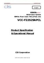
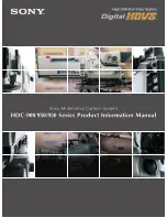
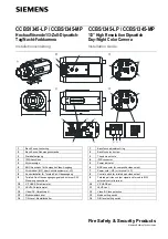
1
Back-Focus-Justierring
2
Back-Focus-Sicherungsschraube
3
Stativbefestigung
4
IRIS-Anschluss
5
Stromanzeige
6
BNC-Anschluss für Composite Video-Ausgang
7
Stromkabel (-MP) oder Anschlussklemme (-LP)
8
Kontrollschalter für Twisted-Pair-Videoausgang
9
Twisted-Pair-Videoausgangssignal und externer SW-
Steuerungsanschluss
10
V-PHASE-Potentiometer
11
LEVEL-Potentiometer
12
Video/DC-Objektivwahl
13
Moduswahlschalter
14
T/N-Level-Einstellschalter
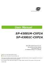
1
Back focus adjustment ring
2
Back focus lock screw
3
Tripod mount hole
4
IRIS connector
5
Power indicator
6
BNC connector for composite video output
7
Power cord (-MP) or terminal (-LP)
8
Control switch for twisted pair video output
9
Twisted pair video output signal and forced to B/W
external control terminal
10
V-PHASE pot
11
LEVEL pot
12
Video/DC lens selection
13
Mode setting switch
14
D/N level setting switch