background image

Siemens 

Siemens 

Siemens 

Siemens 

Siemens Industry

Industry

Industry

Industry

Industry,,,,, Inc.

 Inc.

 Inc.

 Inc.

 Inc.

Building 

Building 

Building 

Building 

Building T

TT

TTec

ec

ec

ec

echnologies Di

hnologies Di

hnologies Di

hnologies Di

hnologies Division

vision

vision

vision

vision

P/N 315-033035-6

INTRODUCTION

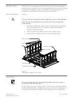
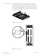
The Model CC-5 Cardcage from Siemens Industry, Inc., (see Figure 1) has five card
slots and occupies two positions on the studs in the backbox or on the optional CAB-
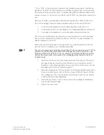
MP Mounting Plate. The Model CC-2 Cardcage (see Figure 2) has two card slots and
occupies one position on the studs in the backbox or on the optional CAB-MP
Mounting Plate. The CC-5 and CC-2 are used for mounting all system circuit card
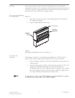
assemblies. They each have two removable terminal block connectors at the top and
one removable terminal block connector at the bottom of each card slot. All field-
wiring connections are made directly to the top of the cardcage while internal power
is connected to the bottom of the cardcage. The two removable terminal block
connectors at the top of each slot are arranged in two rows. The lower row is labeled
1 through 8 and the upper row is labeled 9 through 16. These removable terminal
block connectors are used for connecting power limited external equipment. The
removable terminal block connector located at the bottom of each slot is labeled 17
through 24 and is used for connecting internal power.


Figure 1

Figure 2

CC-5 Card Cage

CC-2 Card Cage

OPERATION

The CC-5 and CC-2 provide a central point for mounting circuit card assemblies. If a
card requires power, it is applied through the removable terminal block at the bottom
of the cardcage. All external devices for the card are connected to the card through
the two removable terminal blocks at the top of the cardcage. The circuit card
assemblies are connected to the HNET and CAN bus through the connectors on the
cardcage.

Note:
Boards shown without card guides installed.

System Cardcage

Installation Instructions
Models CC-5 / CC-2

Summary of Contents for CC-5

Page 1: ...ctly to the top of the cardcage while internal power is connected to the bottom of the cardcage The two removable terminal block connectors at the top of each slot are arranged in two rows The lower row is labeled 1 through 8 and the upper row is labeled 9 through 16 These removable terminal block connectors are used for connecting power limited external equipment The removable terminal block conn...

Page 2: ...e upper card guide has a label on each slot that can be used to identify the module installed in the slot If desired complete the label before inserting the upper card guide 2 Insert the upper card guide and secure with the captive screws 3 Insert the lower card guide and secure with the captive screws GUIDE PIN GUIDE PIN HOLE CAPTIVE SCREW RETAINERS CAPTIVE SCREWS LABELS LOWER CARD GUIDE UPPER CA...

Page 3: ...on adjacent to the CC 5 When only one CC 5 cardcage is to be installed it is normally installed on the left side of a row in the backbox or on the Mounting Plate There is a top and bottom to the Mounting Plate The top is where the word TOP is stamped on the Mounting Plate When the cardcage is mounted correctly on the Mounting Plate it will be flush on the top bottom and left with the Mounting Plat...

Page 4: ...POSTS POSITION 1 POSITION 3 POSITION 4 POSITION 2 POSITION 1 POSITION 3 POSITION 4 POSITION 2 CAB MP Figure 4 Location Of The CC 5 and CC 2 On The Optional CAB MP TOP SLIDE DOWN CARDCAGE UNTIL FLUSH ON TOP LEFT AND BOTTOM CAB MP CC 5 CARDCAGE CC 2 CARDCAGE INSTALL TWO 10 32 SCREWS WHEN ALIGNED WITH THREADED STUDS Figure 5 Mounting The CC 5 and CC 2 On The Optional CAB MP ...

Page 5: ...ble Terminal Block On The CC 5 and CC 2 To Connect The Data Bus The Data bus connectors on the cardcage motherboard are P1 and P2 Refer to Figure 7 They are 60 pin keyed male connectors with connector extractors 1 Open the connector ejectors out of the vertical position and away from the connector body 2 Insert the female cable connector into the male connector P1 or P2 on the cardcage motherboard...

Page 6: ...Control Modules SCM Control Modules FCM Master Voice Microphone LVM and Master Firefighters Telephone FMT The connector is keyed and requires no special instructions for cable connec tion Use cable CCL P N 500 634214 to connect from CAN bus P3 on CC 5 and CC 2 to the desired module CAN power must be supplied to E11 CC 5 or E5 CC 2 Refer to Figure 8 for wiring details CONNECTOR EJECTORS IN VERTICAL...

Page 7: ...s The PSC 12 supplies the power to the two 60 pin Data bus connectors P1 and P2 in the CC 5 and CC 2 The total rating on P1 and P2 for all CC 5s in any given enclosure is as follows 24 VDC 2 Amps max 6 2 VDC 2 Amps max See PSC 12 Installation Instructions P N 315 033060 and the PSX 12 Installation Instructions P N 315 034050 for complete power supply loading calculations ...

Page 8: ... concept It is however necessary to implement and maintain a comprehensive state of the art security concept that is customized to individual security needs Such a security concept may result in additional site specific preventive action to ensure that the building comfort fire safety security management or physical security system for your site are operated in a secure manner These measures may i...

Reviews: