Siemens AC43, User Manual
The Siemens AC43 User Manual is available for free download at manualshive.com. This comprehensive manual provides essential guidelines and instructions to seamlessly operate and maintain your Siemens AC43. Easily access this invaluable resource to optimize the functionality and longevity of your Siemens AC43.
Share
Download


Reviews:
No comments
Related manuals for AC43

Optimus 5100
Brand: Radio Shack Pages: 2

projectorsleeve
Brand: 3M Pages: 14

Blue2
Brand: AbleNet Pages: 9

Air
Brand: Easymount Pages: 2

AC171
Brand: Valore Pages: 5

Multi
Brand: Hama Pages: 40

MINIKIT CHIC
Brand: Parrot Pages: 11

DGIPOD-4655 - DATASHEET FOR IPHONE
Brand: I.SOUND Pages: 1

GV-WM4
Brand: Groov-e Pages: 2

Fun 70 BT
Brand: Hama Pages: 14

HookUpz Smartphone Telescope Adapter
Brand: Carson Pages: 16

POWERSHELL
Brand: Logitech Pages: 152

FANCY STAND
Brand: Hama Pages: 112

Pocket Dual Catchmon
Brand: Megacom Pages: 2
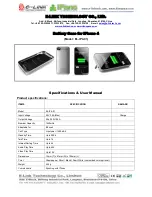
EL-IP4-01
Brand: E-LINK Pages: 4
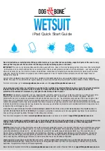
Wetsuit
Brand: Dog & Bone Pages: 8
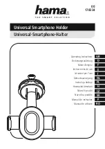
178334
Brand: Hama Pages: 27
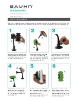
AA-05
Brand: Bauhn Pages: 2


