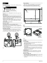
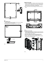
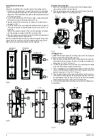
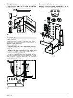
background image

Last update: 02 December 2005

Schranksystem

8MF2000

Cabinet System

DIN EN 50298: 1998-04

Betriebsanleitung / Operating Instructions

Bestell-Nr. / Order No.: A5E00721185

Deutsch

6,(

0(

16

Summary of Contents for 8MF2000

Page 1: ...Last update 02 December 2005 Schranksystem 8MF2000 Cabinet System DIN EN 50298 1998 04 Betriebsanleitung Operating Instructions Bestell Nr Order No A5E00721185 Deutsch 6 0 16 ...

Page 2: ...schränke müssem auf möglichst ebenem Boden aufgestellt werden Unebenheiten ggf durch Blechstreifen ausgleichen Maße der Befestigungspunkte siehe Bild 2 Bild 2 Sockel Maße der Befestigungslöcher des Sockels siehe Bild 3 Bild 3 Allgemeine Maßangaben Die Nennmaße beziehen sich auf die Außenmaße des Grundgerüstes Seitenwand und Rückwand tragen je 9 mm auf Eine Tür trägt ca 26 mm auf Die Profile besitz...

Page 3: ...äche des Haltewinkels und die Oberkante des Querholmschenkels müssen in einer Ebene liegen 2 Das Bodenblech mit Dünnblechschrauben PM 5x10 an den Haltewinkeln befestigen Bild 6 Zwischenwand einbauen 1 Die Distanzgummis in gleichmäßigen Abständen der entsprechenden Loch reihen der beiden seitlich zu verbindenden Gerüste stecken Die Lochreihe ist 60 mm von der Gerüstaußenkante entfernt 2 Die Zwische...

Page 4: ...ankbreite 900 mm verschrauben siehe Bild 8b Bild 8a Bild 8b Montageplatte befestigen 1 Die 4 Befestigungswinkel mit Einziehbolzen M 8x15 Kontaktscheiben 8 und Muttern M 8 am Gerüst befestigen siehe Bild 9 2 Die Montageplatte auf die unteren Winkel stellen und zuerst an den oberen Winkeln mit gewindefurchenden Schrauben PM 6x12 befestigen Bild 9 Tür einbauen Eine 8MF2000 Tür hat 3 Haltepunkte auf d...

Page 5: ... auf den Erdungsbolzen M 6 der Tür mit 3 Nm aufschrauben siehe Bild 12 2 Kabelschuh des Schutzleiterseiles Scheibe A 6 4 und Federring 6 auf den Er dungsbolzen M 6 stecken und mit Sechskantmutter M 6 mit 7 Nm befestigen 3 Gewindebolzen M 6x15 durch eine Bohrung des Seitenrahmens stecken Kontaktscheibe 6 Kabelschuh des Schutzleiterseiles Scheibe A 6 4 und Feder ring 6 aufstecken und mit Sechskantmu...

Page 6: ...nets should preferably be set up on level ground If necessary use sheet metal strips to compensate for unevenness For information regarding the mounting point dimensions see Figure 2 Fig 2 Base For information regarding the base mounting hole dimensions see Figure 3 Fig 3 General dimensions The nominal dimensions refer to the outer dimensions of the basic frame Add 9 mm each for the side and back ...

Page 7: ...nd the upper edge of the cross member leg must be on the same plane 2 Mount the bottom plate to the mounting angles with PM 5x10 sheet metal screws Fig 6 Installing the internal partition 1 Insert the rubber spacers at regular intervals into the respective rows of holes of the two frames to be joined laterally The distance between the row of holes and the outer edge of the frame is 60 mm 2 Mount t...

Page 8: ...a Fig 8b Mounting the mounting plate 1 Mount the 4 mounting angles to the frame with M 8x15 threaded bolts 8 contact washers and M 8 nuts See Figure 9 2 Place the mounting plate onto the lower angles and first mount them to the upper angles using PM 6x12 thread ridging screws Fig 9 Installing the door The 8MF2000 door has 3 stop points on the hinge side and 3 on the locking rod side to be used as ...

Page 9: ...conductor connection of the doors See Figure 12 2 Place the cable lug of the protective conductor wire the A 6 4 washer and the 6 spring washer onto the M 6 grounding stud and secure them with a M 6 hexagonal nut using a tightening torque of 7 Nm 3 Insert the M 6x15 threaded bolt through one of the holes of the side frame attach the 6 contact washer the cable lug of the protective conductor wire t...

Page 10: ...tance siemens com Internet www siemens de lowvoltage technical assistance Technical Support Telephone 49 0 180 50 50 222 Element Element Größe Size Moment Torque Nm 15 Werkzeug Tool Verbindung Connection PM 6 8 T 30 verschiedene Teile Various parts PM 5 x 10 8 T 25 Umhüllung Gerüst Paneling frame M 5 x 17 handfest Hand screwed Z2 Zierblende Trimstrip M 4 1 5 SW 8 Tür Door 6 12 elektrisch Electrica...

Reviews: