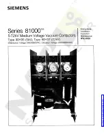
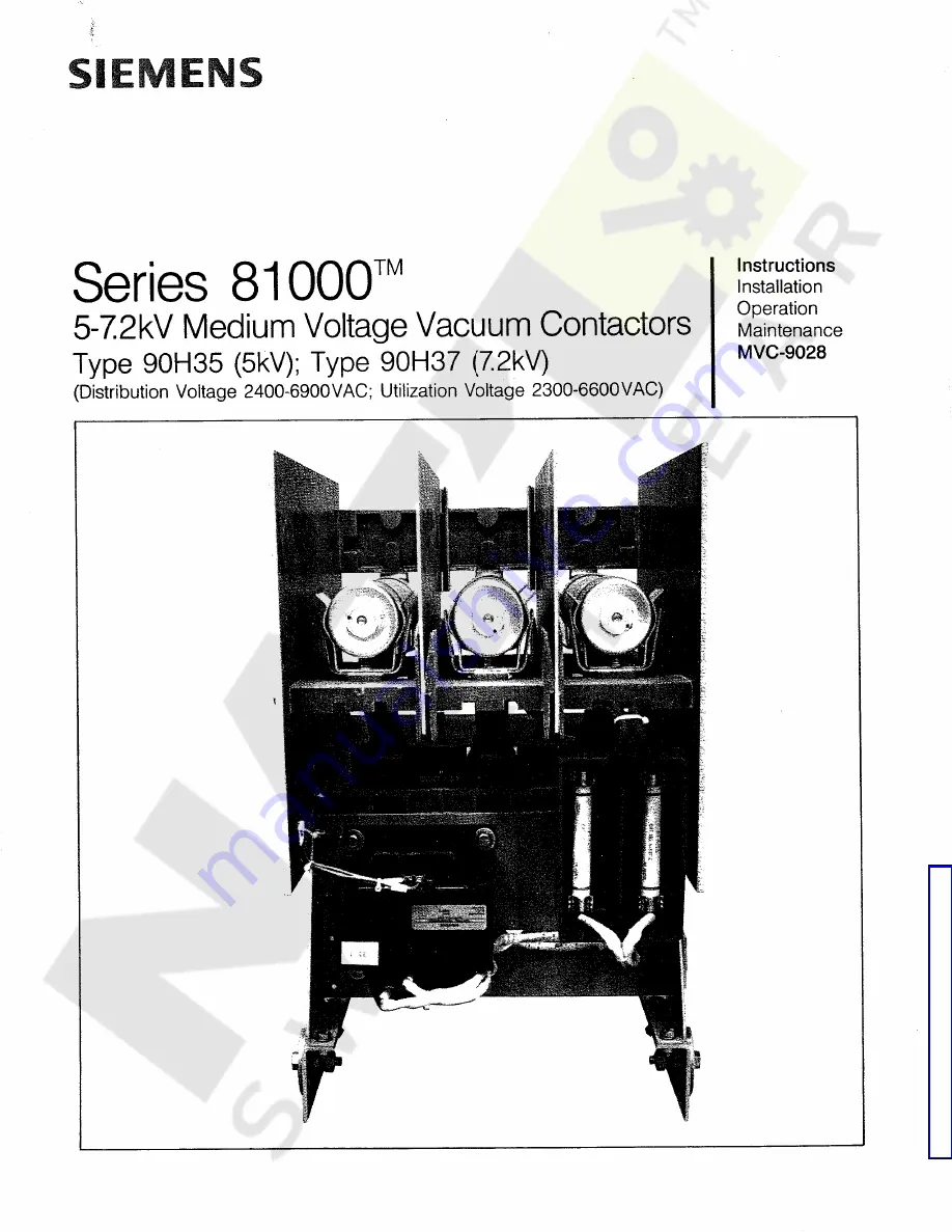
Summary of Contents for 81000 90H35

Page 1: ...stallation Operation Maintenance MVC 9028 Series 81000 5 7 2kV Medium Voltage Vacuum Contactors Type 90H35 5kV Type 90H37 7 2kV Distribution Voltage 2400 6900VAC Utilization Voltage 2300 6600VAC Courtesy of NationalSwitchgear com ...

Page 2: ...Courtesy of NationalSwitchgear com ...

Page 3: ... Control Circuit Diagrams Typical Control Circuit Diagrams Typical Control Circuit Diagrams Maintenance Safety Phase Barrier and Dust Cover Removal and Re Installation BlownFuse Trip Mechanism 14 1 15 1 15 2 16 2 17 3 18 3 18 18 4 18 4 18 5 19 6 19 6 19 7 19 7 19 19 8 19 8 9 20 10 11 22 23 12 24 25 12 12 NOTE These instructions do not purport to cover all details or variations in equipment nor to ...

Page 4: ...actor are 18inches 457mm wide by 27 5 inches 699mm high by 23 87 inches 606mm deep The vacuum contactor with single or double barrel power fuses can be installedin Series 81000 Class E2 controllers of either one two or three high construction The Type 90H3 vacuum contactor consists of 1 a low voltage section which contains the main coil drive and auxiliary contacts 2 a medium voltage section which...

Page 5: ...es to the far right position The nut 3 4 of the vacuum interrupter 4 1 is thus released so that the atmospheric pressure can press the moving contact against the fixed contact The drive mechanism is constructed so that the nut 3 4 never comes into contact with the drive lever 3 1 wheninthe ON position This ensures that the ON switching position is always reached definitely and completely Blown Fus...

Page 6: ...ored energy capacitor source which is charged from the normal control source The stored Nomenclature The contactors can be identified through the nomenclature description shown below x x x x x x x x x x x x I J CONTACTOR CONTINUOUS AMPERE RATING H3 360A H6 720A VARIABLE IF USED L LATCHED CONTACTOR S SPEC1AL CONTACTOR SEE DWG A DRAWOUT CONTACTOR F FUSE CARRIAGE FOR 720A CONTROLLER T DRAWOUT CONTACT...

Page 7: ... loss is discovered A description of the damage and as much identification information as possible should accompany the claim Handling For convenience and safety in lifting or moving the contactor the lifting device similar to that shown in Figure 2 should be purchased Figure 2 Lifting Device A crane or hoist is also recommended tohandle the contactor if the lifting device is not available Refer t...

Page 8: ...st be avoided when handling the contactor 6 Lift the contactor only high enough to clear obstructions on the floor 7 Take care to avoid collisions with structures other equip ment or personnel when moving the contactor 8 Never lift a contactor above an area where personnel are located Storage The contactor must be stored in a clean dry dust and condensation free environment if it cannot be placed ...

Page 9: ...ed h Vacuum type interrupters can produce x rays if they are subjected to sufficiently highvoltages The vacuumbottlesusedin Siemens type 90H3 contactors will not produce harmful x rays at applied vol tages of 40 kV or less High potential dielectric tests shouldbe limited to amax imum value of 13 250 volts RMS AC to allow an adequate safety margin for protection of personnel from x radiation Site P...

Page 10: ...erated at the following site altitudes From 4100 ft below S L to 650 ft above S L From 650 ft below S L to 4100 ft above S L From 4100 ft above S L to 8200 ft above S L The vacuum contactors are set at the factory for a site altitude from 650 ft below sea level to 4100 ft above sea level Figure 5 Altitude Adjustment Information Plate Adjustment on the bottom of the vacuum contactor is neces sary i...

Page 11: ...e Figures7 8 and 9 Pre Energization Check WARNING Failure to properly check out this equipment prior to energization can cause seriousinjury bum or damage Perform the following checks before energizingequipment Operating Data 125 Volt DC Supply 220 Volt DC Supply 230 Volt AC Supply 115 Volt AC Supply Description 125 Volts RatedControl Voltage 220 Volts 240 Volts 120 Volts 176 Volts 100 Volts Pick ...

Page 12: ... f f2 HI o I M if 11 K MR 1 1 M X AC M X 1 R1 LEGEND CPT Control Power Transf CXFU Fuse for CPT Sec Line Switch Interlock MainContactor Master Relay Auxiliary Relay Rectifier Contactor Engagement WarningLight Economy Resistor RackingSwitch Interlock Fuse for Test Power LSI Additional Auxiliary Contacts M MR X M M M M TT 0 0 0 0 0 0 0 0 12 13 14 15 16 17 18 19 MX REC RL R1 RSI TFU Figure 7 Series 8...

Page 13: ...h Tm M ECH d 1 TRIP LEGEND CPT Control Power Transf CXFU Fuse for CPT Sec Line Switch Interlock MainContactor Master Relay Auxiliary Relay Rectifier Contactor Engagement Warning Light Economy Resistor RackingSwitch Interlock Trip Coil LM LMX LSI LM Additional Auxiliary Contacts MR LMX LM LM LM LM LM REC vr vrv vjo to vtO vto 0 0 0 0 0 0 0 0 0 0 4 5 12 13 14 15 16 17 18 19 RL R1 RSI T Figure 8 Seri...

Page 14: ...itch Interlock Main Contactor Master Relay Auxiliary Relay Bleeder Resistor Charging Resistor Rectifier Contactor Engagement Warning Light Economy Resistor Racking Switch Interlock Surge Suppressor Molded into REC 4 Block Trip Coil Fuse for Test Power CPT CXFU ECH TRIP LSI LM MR LM LMX LMX Rb Rc REC Additional AuxiliaryContacts RL LM LM LM LM TT TT Tsl TT k b 0 0 0 0 0 0 4 5 12 13 16 17 18 19 R1 R...

Page 15: ...inside the medium voltage sec tion It is necessary to remove these barriers to perform main tenance on the vacuum contactor First remove the inter phase barriers by sliding upward and out A tab located on the rear of each interphase barrier engages a notch in the dust cover and locks it into the assembly Once the inter phase barriers are removed the dust cover will slide out toward the rear discon...

Page 16: ...facing forward away from discon nect fingers on contactor 2 With the trip bar in its normal spring return deactivated position the trip bar should rest against the stop screw on the right handcontactor side plate as shown in Figure 10 The trip bar must be held in this position while performing adjustments 3 and 4 3 Adjust each of the three plunger assemblies shown in Figure 10 to obtain a 1 16 1 6...

Page 17: ... test voltages can causeharmfulx radiation to be emitted from vacuum bottles Do not exceed 13 250 volts RMS AC or 19 kV DC when performing dielectric tests AWARNING Accidental contact with dielectric test equipment can cause shock burn or electrocution Dielectric testing should only be con ducted by qualified personnel Refer to test device instructions for safety instruc tions With the vacuum cont...

Page 18: ...ge sources are disconnected Refer to Figure 14 At the pole whose interrupter is to be replaced Loosen the M8 hexagon socket bolt 5 1 of the flexible connection 4 3 and hold the nut 5 3 with a flat wrench 13mm as shown in the Figure 14 Loosen the M8 locknut 4 5 of the articulated bolt 4 2 holding the moving contact 4 1 2 of the vacuum interrupter with a flat wrench at location A 17mm Unscrew the ar...

Page 19: ...ition and lock with nut 4 5 Slip contact washer 4 4 and flexible connection 4 3 onto the articulated bolt Screw the bolt into the moving contact 4 1 2 of the vacuuminterrupter Screw the articulated bolt into the moving contact until it comes up against the bottom of the contact thread or the locknut comes up against the cup 3 3 Tighten the locknut 4 5 at the same time holding the moving contact 4 ...

Page 20: ...in Coil Replacement There are two main coils To gain access to the main coils first remove the two side plates from the low voltage section The main coil leads are connected to the control circuit with push on terminals and can be removed by pulling off The main coils may be removed by removing the two M8 hexagonsocketheadboltsfromtheunderside of the contac tor See labelon undersideof contactor wh...

Page 21: ...d by the size of hardware used 1 Metal to Metal Apply standard torque as listed 2 Metal to lnsert molded in compound part Apply ap proximately 2 3 of standard torque 3 Compound to lnsert molded in compound part Apply approximately 1 2 of standard torque 4 Compound to Compound Apply approximately 1 2 of standardtorque Periodic Cleaning Accumulation of dust andforeign material such as coal dust ceme...

Page 22: ...verload relay Fuse Holders Replacefuseholdersif theinsulationmounts barriers or fuse clipsshow signsof damage deterioration heating distortion or looseness Fuses Always replace all three fuses in a three phase circuit even though only one or two are open circuited since internal damage suffered by fuses not replaced could result in nuisance shut down later Performthe Pre EnergizationCheck procedur...

Page 23: ...blems 1 Manufacturer s serial number and part number if available 2 Nameplate data on contactor 3 Duty cycle and any details of operation 4 Length of time in service and approximate total number of operations 5 Voltage current and frequency 6 Description of problem 7 Any other pertinent information ikwARNING Accidental contact with energized components can cause shock bum or electrocution Disconne...

Page 24: ...lay If the magnet assembly has been removed for coil replacement check that the flat washers shims that were beneath it have been reinstalled in the original locations Improper number or wrong size shims installed under magnet assembly Adjust altitude setting as required High Altitude Properly adjust switch or replace Fluttering control relay such as pres sure or temperature switch Coil Rectifier ...

Page 25: ...e Rail Side Angle L H Side Plate R H Side Plate Insulator Molding CPT Mounting Plate CPT Fuse Block Assembly Wheel Wheel Shaft Insulator Molding Copper Spacer Copper Spacer LSI Mounting Bracket Barrier Interphase Barrier Striker Bar Guide LSI Finger LSI Support Finger Assembly Line Finger Assembly Load CPT Fuse Clip Fuse Clip Assembly Line Fuse Clip Assembly Load Terminal Block Bracket Interlock L...

Page 26: ...Parts Page 23 Figure 20 Vacuum Contact Front View 5kV Courtesy of NationalSwitchgear com ...

Page 27: ... R H Side Rail Side Angle Barrier Mounting Angle L H Side Plate R H Side Plate Insulator Molding CPT Mounting Tray Corner Brace CPT Fuse Block Wheel Wheel Shaft Copper Bar Copper Bar Insulator Molding Copper Spacer Copper Spacer LSI Mounting Bracket Support Angle Barrier Interphase Barrier Striker Bar Guide LSI Finger LSI Support Finger Assembly Line Finger Assembly Load CPT Fuse Clip Copper Bar A...

Page 28: ...Parts Page 25 Figure 21 Rear View Vacuum Contactor 7 2kV Figure 22 Vacuum Contactor Front View 7 2kV Courtesy of NationalSwitchgear com ...

Page 29: ...Parts Page 26 Figure 23 Vacuum Bottle 5 7 2 kV j Figure 24 Gage Plate Courtesy of NationalSwitchgear com ...

Page 30: ...tallation opera tion and maintenance as well as upon proper designandmanufacture Failure to followcertainfundamentalinstallationand maintenance requirements may lead to personal injury and the failure and loss of control equipment as well as damage to other property Caution For thepurposeof this manualandproduct labels CAUTION indicates minor personalinjury or property damagecanresult if proper pr...

Page 31: ... Courtesy of NationalSwitchgear com ...

Page 32: ...Siemens Energy Automation Inc Electrical Apparatus Division P O Box 29503 Raleigh NC 27626 919 365 6660 SIEMENS PRINTED INU S A MVC 9028 10 91 Courtesy of NationalSwitchgear com ...

Reviews: