


KIT INSTALLATION INSTRUCTION
Siemens
Energy & Automation
Kit Part Numbers: 16300-468 Standard Flow
15900-407
16330-469 High Flow
Rev.
4
16300-470 Low Gain Flow
January
2009
Series 760 Valve Positioner
Output Capacity Kit
Install an Output Capacity Kit to match Positioner flow output to an Actuator. This Instruction
describes installation of the kits listed above. Refer to the Series 760 Valve Positioner Installation
and Service Instruction, SD760, as needed during installation of a kit.
KIT CONTENTS
Each Kit contains the items listed below. Note that the Spool Valve (Spool Block and Spool) in each of the three kits
is different.
If several kits are being installed, keep the parts in each kit separate.
Item Quantity
Spool Valve (Spool and Spool Block)
1
Spool Clip
1
Valve Block Gasket, Viton®/Nomex®
1
Valve Block Gasket, Neoprene/Nylon
1
8-32 Spool Block Mounting Screws
2
Kit Installation Instruction
1
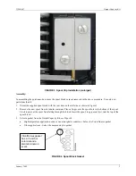
KIT INSTALLATION
The area in which the Kit is installed must be clean. Hands and tools must also be clean. Keep all Kit parts in the
supplied bag until they are to be installed to prevent contamination by dust, dirt, fumes, and other environmental
contaminants. Contaminants can cause the spool to stick or operate unevenly.
IMPORTANT
Move the positioner to a clean location before installing the kit. If this is not possible, contaminants
must be prevented from entering exposed air passageways during kit installation.
WARNING
Electrical shock hazard
Explosion hazard
Can cause death or injury
•
Remove power from all wires and terminals before working on
equipment.
•
In potentially hazardous atmosphere, remove power from equipment
before connecting or disconnecting power, signal, or other circuit.
•
Observe all pertinent regulations regarding installation in hazardous
area.


