instabus EIB
Technical Product Information
September 2001
Time Switch 4 Channel REG 372
5WG1 372-5AR01
Siemens AG
REG 372, 4 pages
Technical Manual
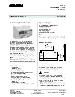
Product and Applications Description
The time switch REG 372 is a DIN-rail mounted
device laterally attached to the bus coupling unit
REG 110 (to be ordered separately, order number:
5WG1 110-5AR01). During this it occupies 4 address-
ing locations of the bus coupling unit. Via the four
channels time controlled applications such as illumina-
tion, heating or shutters can be switched on or off. It
can be used as daily, weekly or yearly clock controller.
By connecting an aerial FA and a power unit NT DCF77
the clock controller itself automatically sets the up-to-
date daytime and date (MEZ).
With a reading button the set switching times, date
referenced inputs and 1x-switching commands can be
trialled.
The bus coupling unit REG 110, the power unit
NT DCF77 and the radio aerial FA are not contained in
the volume of delivery and must be ordered separately
Operational specifications
•
4 channels
•
response margin
•
radio interface DCF 77
•
date referenced input
•
single days and date ranges
•
free weekday and channel block establishment
•
yearly, weekly and daily program
•
322 memory locations
•
no double tasks of the push-buttons
•
automatic summer-/winter time conversion
•
possibility of setting the program: every minute
•
shortest switching time 1 minute
•
rapid impulse
•
preliminary selection (override)
•
switching condition permanent ON, permanent OFF
Application Programs
11 S4 Time switch 4 Channel 241A01
•
4 inputs for time switch
•
control start event
•
control finishing event
•
delayed on-switching
•
delayed off-switching
•
channel connection (AND/OR)
Note
Before programming the device has to be supplied with
voltage for at least 6 minutes (charge the accumulator).
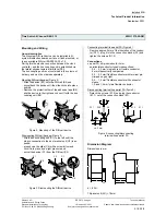
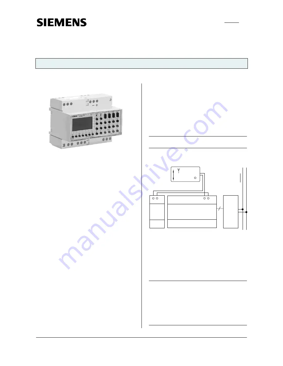
Example of Operation
PEI
bus
coupling
unit
REG 110
FA
aerial DCF77
Frankfurt / Main
signal
- +
- +
time clock controller REG 372
in
st
ab
us
EI
B
power unit
NT
DCF 77
Installation Instructions
•
The device may be used for permanent interior
installations in dry locations within high voltage
distribution board or small casings.
V
WARNING
•
The device may be built into distribution boards
(230/400V) together only with appropriate VDE-
devices and must be mounted and commissioned by
an authorised electrician.
•
Free DIN rail areas must be covered with covers,
order no. 5WG1 192-8AA01.
•
The prevailing safety rules must be heeded.
•
The device must not be opened. A device suspected
faulty should be returned to the local Siemens office.
Automation and Drives Group
Electrical Installation Technology
Siemens AG 2001
Update: http://www.siemens.de/installationstechnik
P.O.Box 10 09 53, D-93009 Regensburg
Subject to change without prior notice
2.18.2.2/1


