background image


Installation Instructions

Document No. 563-202 

March 12, 2008


WFLN Series 

Wireless Transceiver Tool (TLX) 

(Version 2.x)


Item Number 563-202, Rev. CA


Page 1 of 4


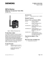
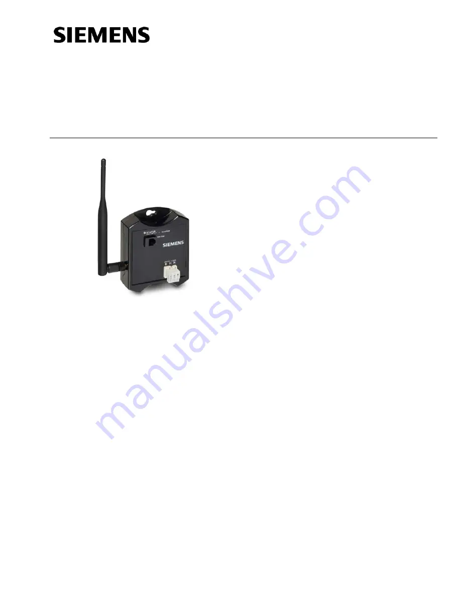
Figure 1. Wireless Transceiver Tool. 

Product Description 

The Wireless Transceiver Tool (TLX) is a wireless 
transceiver used for WFLN commissioning and 
gathering information from all the components of the 
Wireless Field Level Network (WFLN): the Field 
Panel Transceiver (FPX), Field Level Network 
Transceiver (FLNX), and mesh Wireless TEC Room 
Temperature Sensor (WRTS). Through Microsoft

®


HyperTerminal, you can view the WFLN information 
that the TLX gathers, such as node configuration 
data and communication link quality. 

Product Number 

563-056 

Wireless Transceiver Tool (TLX) 
with WRTS Support (Version 2.x) 
 
Includes Direct Mount Antenna, 
Power Cable, and 24 Vac 
Transformer 

Accessories 

540-143 

MMI cable (9-pin to RJ-11, RS-232) 

Related Products 

Wireless Field Level Network (WFLN) 

563-055 

Wireless Field Panel 
Transceiver (FPX) 

563-054 

Wireless Field Level Network 
Transceiver (FLNX) 

QAA2290.EWSC  Wireless TEC Room 

Temperature Sensor (WRTS) – 
Sensing only 

QAA2290.DWSC  Wireless TEC Room 

Temperature Sensor (WRTS) – 
Sensing with Temperature 
Display 

QAA2290.FWSC 

Wireless TEC Room 
Temperature Sensor (WRTS) – 
Sensing with Override, Setpoint, 
and Temperature Display 

Expected Installation Time 

3 minutes 

Required Tools and Materials 


Small flat-blade screwdriver 


Summary of Contents for 563-056

Page 1: ...LX gathers such as node configuration data and communication link quality Product Number 563 056 Wireless Transceiver Tool TLX with WRTS Support Version 2 x Includes Direct Mount Antenna Power Cable and 24 Vac Transformer Accessories 540 143 MMI cable 9 pin to RJ 11 RS 232 Related Products Wireless Field Level Network WFLN 563 055 Wireless Field Panel Transceiver FPX 563 054 Wireless Field Level N...

Page 2: ...onnect the 24 Vac transformer to a power source 3 Position the TLX antenna in a vertical orientation up or down and ensure it is securely attached 4 At the computer start HyperTerminal and set the following communication parameters Connect using COMM x x computer s COMM port used to connect to the TLX Bits per second 38400 Data bits 8 Parity None Stop bits 1 Flow control None 5 Press ENTER to disp...

Page 3: ...attery Snap Connector Wiring TLX Status LED The Status LED indicates the current operation mode and communication status of the TLX Table 1 Status LED Blink Patterns LED Blink Pattern Indicates the TLX is OFF Not powered Green quickly blinking ON and OFF every 0 25 second Powered communicating with at least one node FPX FLNX WRTS Green slowly blinking ON and OFF every 1 0 second Powered but not cu...

Page 4: ...ll not occur in a particular installation If this equipment does cause harmful interference to radio or television reception which can be determined by turning the equipment off and on the user is encouraged to try to correct the interference by one of the following measures Reorient or relocate the receiving antenna Increase the separation between the equipment and receiver Connect the equipment ...

Reviews: