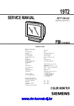
background image

CHASSIS

SERVICE MANUAL

SPECIFICATIONS

19T2

F99

AEP Model

Chassis No. SCC-L30T-A

COLOR MONITOR

Dimensions and weight

CRT:

46 cm (19")

Visible diagonals:

46 cm

Dot pitch:

0.24 - 0.25  mm (slot mask)

Maximal resolution:

1600 x 1200 pixels

Preset display area:

352 mm x 264 mm

Dimensions (W x H x D):

449 mm x 463 mm x 463 mm

Weight:

26 kg

Accessories:

Power cable (1.8 m)

Storable display modes:

25 (10 of which are preset)

Electrical data

Video:

analog, positive, 0.7 Vpp, 75 Ohm

Synchronization:

Separate Sync. TTL
Composite Sync. TTL/ Sync. on Green

Horizontal frequency:

30 kHz .... 107 kHz (multi-scanning)

Refresh rate:

48 Hz .... 120 Hz

Maximum pixel rate:

230 MHz

Power supply:

180 V -264 V, 50 Hz - 60 Hz   3 Hz,
< 1 A max. at 220 V

Power consumption:

(see power management):

< 145 W (ON, Normal mode)
< 15 W (Standby mode)
< 15 W (Suspend mode)
< 3 W (OFF mode)

Environmental conditions

Environment class 3K2, IEC 721

Rated range of operation:

15 

°

C .... 35 

°

C

Humidity:

20 %  .... 85 %

Limit range of operation:

°

C .... 40 

°

C

Humidity:

20 %  .... 85 %

Condensation must be avoided.

www.rtv-horvat-dj.hr

Summary of Contents for 19T2

Page 1: ...t Electrical data Video analog positive 0 7 Vpp 75 Ohm Synchronization Separate Sync TTL Composite Sync TTL Sync on Green Horizontal frequency 30 kHz 107 kHz multi scanning Refresh rate 48 Hz 120 Hz Maximum pixel rate 230 MHz Power supply 180 V 264 V 50 Hz 60 Hz 3 Hz 1 A max at 220 V Power consumption see power management 145 W ON Normal mode 15 W Standby mode 15 W Suspend mode 3 W OFF mode Enviro...

Page 2: ...HIS MANUAL FOLLOW THESE PROCEDURES WHENEVER CRITICAL COMPONENTS ARE REPLACED OR IMPROPER OPERATION IS SUS PECTED After correcting the original service problem perform the fol lowing safety checks before releasing the set to the customer 1 Check the area of your repair for unsoldered or poorly sol dered connections Check the entire board surface for solder splashes and bridges 2 Check the interboar...

Page 3: ...our PC i The service life of your monitor will be extended if the OFF mode is switched to after 30 minutes at the earliest setting in screen saver in your PC s BIOS setup or in the OSD menu When the monitor is switched to OFF mode by the power management system a power consumption of about 3 W is maintained to feed the circuit for redrawing the screen contents To cut off power consumption totally ...

Page 4: ...RITY NO NO NO NO NO NO INT NON INT NON INT NON INT NON INT NON INT NON INT NON INT 2000 2 18 VER TIMING SPECIFICATION MODE AT PRODUCTION MODE 1 MODE 2 MODE 3 MODE 4 MODE 5 MODE 6 RESOLUTION 720 X 400 640 X 480 640 X 480 800 X 600 800 X 600 1024 X 768 CLOCK 28 325 MHz 25 175 MHz 36 000 MHz 56 250 MHz 67 500 MHz 94 500 MHz HORIZONTAL H FREQ 31 472 kHz 31 469 kHz 43 269 kHz 53 674 kHz 63 920 kHz 68 6...

Page 5: ... 4 2 8 Harness Location 2 5 3 SAFETY RELATED ADJUSTMENT 3 1 4 ADJUSTMENTS 4 1 5 DIAGRAMS 5 1 Block Diagrams 5 1 5 2 Frame Schematic Diagram 5 5 5 3 Circuit Boards Location 5 6 5 4 Schematic Diagrams and Printed Wiring Boards 5 7 1 Schematic Diagram of A Board 5 9 2 Schematic Diagrams of D a b c Board 5 11 3 Schematic Diagrams of N H Boards 5 19 5 5 Semiconductors 5 21 6 EXPLODED VIEWS 6 1 Chassis ...

Page 6: ...nt notes at the beginning of this manual Do not cover the ventilation openings of the monitor If you are assembling monitors beside each other there must be a minimum distance of 30 cm between monitors of the same constructional type to avoid image distortion With different monitors the distance must be increased if necessary Color monitor 19T2 8 English A26361 K616 Z100 1 5E19 1 2 1 Power connect...

Page 7: ...n contents are redrawn and full power is restored The length of the individual stages is determined by the power management system of the PC For detailed information on how energy saving mode operates refer to the Operating Manual or Technical Manual of your PC i The service life of your monitor will be extended if the OFF mode is switched to after 30 minutes at the earliest setting in screen save...

Page 8: ...ting the brightness of the background Setting the contrast between the foreground and background Setting picture position and size SIZE CENTER The set values for the picture position and size are only saved for the current input signal Calling the SIZE CENTER setting window Horizontal picture position H CENTER Shifting the picture to the left or to the right Vertical picture position V CENTER Shif...

Page 9: ...rom English default setting German French Spanish Italian Swedish Dutch Russian and Japanese Setting monitor options OPTION You can degauss the monitor in the settings window OPTION you can set the Moiré correction change the OSD position lock release the buttons for monitor settings and restore original monitor colors The set value for the Moiré correction is only saved for the current input sign...

Page 10: ...button on the front of the monitor either the adjustment of a selected function can be specifically reset to the factory setting all settings for the current input signal can be reset or all input signals reset Resetting a selected function to the factory setting Select the function in the OSD menu to be reset Press the factory settings button Color monitor 19T2 16 English A26361 K616 Z100 1 5E19 ...

Page 11: ...ronics Standard Association Display Data Channel is used as the communications interface between the monitor and the PC If your PC is equipped with a VESA DDC compatible VGA interface it can automatically read the data for ensuring optimum operation from your monitor and select the appropriate settings i If the monitor 19T2 is not yet displayed in the list of monitors you can select one of the fol...

Page 12: ...rating properly In this case check the PC If the color bars do not appear this may be due to a fault in the monitor Please contact our customer service center with a description of the problem The power indicator flashes orange Switch the monitor off and on again If the power indicator continues to flash orange there may be a fault in the monitor Determine the interval at which the indicator flash...

Page 13: ...perature and colors COLOR Screen display has lines is dull or blurred Set the brightness and contrast see Operation of the monitor Degauss the monitor see Operation of the monitor section Setting monitor options OPTION Set the convergence and reduce the Moiré correction see Operation of the monitor section Setting monitor options OPTION The screen display is flickering Set an ergonomic refresh rat...

Page 14: ...ush in the tip of a screwdriver about 5mm to unlock the two claws 1 Two claws Two claws 2 Two screws BVTP 4 x 16 Bezel assembly Cabinet Cabinet 5 Four screws BVTT 4 x 8 7 Three screws BVTT 4 x 8 8 Video shield 3 Two screws BVTT 4 x 8 1 2 EMI shield Upper 4 Side cover L 6 Side cover R Three screws BVTT 4 x 8 www rtv horvat dj hr ...

Page 15: ...x 8 2 Cable stopper 5 Three screws BVTT 3 x 8 CN601 CN600 CN303 8 D board N board 6 Screw P 3 5 x 20 7 Two screws BVTP 3 x 8 2 Screw BVTT 4 x 8 4 Rear shield complete assembly 1 Cable cover 3 Widening the chassis toward the direction A disengage two claws A A Referring to 2 3 disconnect five connectors CN303 CN305 CN306 CN309 and CN311 www rtv horvat dj hr ...

Page 16: ...fore removing the bezel assembly secure the picture tube shield at the positions shown with the arrow diagonal two places to prevent the picture tube from falling Use the screws BVTT4x8 that fix shield 3 5 4 2 1 2 6 H BOARD REMOVAL 2 5 SERVICE POSITION 2 3 AC inlet D board A board 1 2 3 www rtv horvat dj hr ...

Page 17: ...material 2 Don t press the rubber hardly not to damage inside of anode caps A material fitting called as shatter hook terminal is built in the rubber 3 Don t turn the foot of rubber over hardly The shatter hook terminal will stick out or damage the rubber REMOVAL OF ANODE CAP NOTE Short circuit the anode of the picture tube and the anode cap to the metal chassis CRT shield or carbon painted on the...

Page 18: ...1 CN600 H board Degaussing coil N board FBT A board Picture tube Rear shield Side cover L CN11 CN2001 CN1 CN702 CN701 CN904 CN601 CN315 CN309 CN301 CN313 CN302 CN1003 CN1002 CN1004 D board AC inlet CN310 CN306 CN311 CN303 www rtv horvat dj hr ...

Page 19: ...nd GND and make sure that OCP will function Power LED will vanish and the sound chi chi chi will be heard and cut off AC input promptly e Power Supply Operation Check 1 Apply AC100 V to the D Board 2 Make sure that the line voltage at the both ends of C621 is 200 3 0 VDC HV Regulator Circuit Check HV Protector Circuit Check Beam Current Protector Circuit Check When replacing or repairing parts in ...

Page 20: ...sembling the chassis 7 Perform auto degaussing 8 Attach the wobbling coil to the designated part of the CRT neck 9 Attach the sensor of the landing adjustment unit on the CRT surface 10 Adjust the DY position and purity and the DY tilt Note Use purity magnet on the DY 11 Fasten DY with screw Note Torque 22 2 kg cm 2 2 0 2 Nm 12 Perform auto degaussing 13 Using two wedges adjust vertical pins so as...

Page 21: ...ition of each magnet and TLH plate a Align the protrusion marked with an arrow White Balance Adjustment Specification 1 9300 K x 0 283 0 015 y 0 298 0 015 All White 2 5000 K x 0 346 0 015 y 0 359 0 015 All White Vertical and Horizontal Position and Size Specification Focus adjustment Adjust the focus volume 1 and 2 for the optimum focus Convergence Specification 4 2 2 fold poles magnet on the DY 4...

Page 22: ... 3 4 1 2 1KV 1KV CN301 D 7 H1 CN305 G2 C BLOCK G2 HC FC TO FBT FV C KB KR KG HEATER G2 CONT Q001 IC005 G2 CUT OFF CONT TEST19 PC1 FIL Q804 SYNC SEPALATOR Q002 003 V901 PICTURE TUBE 5 11 7 3 2 4 15 7 13 14 6 V SYNCO C BLK DSP RESET IIC SDA IIC SCL H SYNCO H FBP PLL LOCK HD OUT H SHAPE POC CN801 F 14 10 15 9 7 6 5 4 2 1 14 3 V FBP V SAWM V DF DCC2 XDC REFDC YDC YSC XSC D TILT H DF DAC REF CN802 G 42...

Page 23: ...CENT Q517 519 STBY 5V 6 5 1 7 5 3 6 1 9 5 4 7 SCL SDA S CAP CANGE Q511 516 OSCONT OSCIN WC IC1005 ROM OUT IC607 IC401 V OUT 1 1 2 2 3 9 8 7 5 3 2 18 17 16 15 5 1 3 4 2 14 13 12 11 10 1 4 3 3 2 4 2 1 7 7 6 14 11 12 18 10 3 1 5 6 12V H LIN BAL SW Q510 REF 9V 1 4 DGC DGC CN610 1 2 3 AC L NC AC H CN600 F601 D625 AC RECT 15V TH600 TH601 RY601 RY602 LF602 LFT AC IN DGC RELAY DRIVE Q607 IC609 5V REG STBY...

Page 24: ...200V NC NC AC L AC H NC 80V GND H1 12V GND 200V H SYNCO V SYNCO GND 5V 2 NC C SYNC V SYNC H SYNC NC 1KV NC NC GND C BLK STBY 5V BP CLP DDC SCL DDC SDA IIC SDA IIC SCL H FBP GND CPU GND1 CPU GND2 H SYNCO V SYNCO GND 5V 2 NC C SYNC V SYNC H SYNC GND C BLK STBY 5V BP CLP DDC SCL DDC SDA IIC SDA IIC SCL H FBP TO CRT SHIELD USER CONTROL AC IN POWER H DEF HV TO ECS V DY H DY ROTATION VIDEO CABLE VIDEO C...

Page 25: ...Emitter Collector Base Transistor Source Gate Drain Cathode Anode Anode Cathode Anode Anode Divided circuit diagram One sheet of D board circuit diagram is divided into three sheets each having the code D a to D c For example the destination ab1 on the code D a sheet is connected to ab1 on the D b sheet a b 1 Ref No Circuit diagram division code HV ADJ Part Replaced RV901 HV Regulator Circuit Chec...

Page 26: ...HIP 1k CHIP 0 1 25V B CHIP 270k CHIP 0 1 25V B CHIP 0 1 25V B CHIP 0 1 25V B CHIP 0 1 250V 10 250V 0 1 25V B CHIP 0 47 250V 0 47 250V 470k CHIP 470k CHIP 470k CHIP 470k CHIP 470k CHIP 470k CHIP 0 47 250V 0 1 100V 8 2k CHIP 0 022 B CHIP 8 2k CHIP 0 022 B CHIP 0 1 25V B CHIP 100 CHIP 220µH 470k CHIP 470k CHIP 470k CHIP 0 1 25V B CHIP 470 16V 0 1 25V B CHIP 8P WHT S MICRO 470 CHIP 470 CHIP 470 CHIP 0...

Page 27: ...HIP 1k CHIP 1k CHIP 8 2k CHIP 220 CHIP 220 CHIP 220 CHIP R1007 1k CHIP R1008 1k CHIP 1k CHIP 1k CHIP 100 CHIP 100 CHIP 10k CHIP 0 22 100V PT 0 01 50V B CHIP 0 1 25V F CHIP 15P 1k CHIP 100 CHIP 220 CHIP 220 CHIP 8P WHT S MICRO 4 7 1W RS 4P WHT 0 CHIP 0 CHIP 10k RN CP 100k 1 2W RC 4 7k RN 3300p B CHIP 22 15k RN 10k CHIP 47k CHIP 8P WHT S MICRO 0 01 B CHIP 0 CHIP 3 3k RN CP 33k CHIP 100 CHIP 4700p B ...

Page 28: ...RD 0 01 MPS 1 8 10W RN 27 1W RS 4700p 1 8kV PP HZS182 TE 0 047 250V MPS 22 FPRD HST 0 1 25V F CHIP 0 16 400V PP 1 5 250V PP 0 68 250V PP 0 01 50V B CHIP 0 33 250V PP 0 15 250V PP 0 082 250V PP 0 033 400V PP 0 01 50V B CHIP 0 01 50V B CHIP 0 01 50V B CHIP 0 01 50V B CHIP 0 0047 B CHIP 10 FPRD LCT 0 1 25V B CHIP 0 47 3W RS 0 1 25V F CHIP 0 1 25V F CHIP 0 47 250V 1SS133T 77 JW 5 0 39 1W RS 820k CHIP ...

Page 29: ...RC 4 7k 1 2W RC 4 3k RN CP 2 2 FPRD RGP02 17PKG23 RGP02 17PKG23 100k RN 47k RN CP 10k CHIP 1M RN 0 01 2kV F 100 25V 100 25V 100k RN CP 47k CHIP 100k CHIP 3 3 RD16ES T1B2 10k CHIP 47k CHIP 330k 1 2W RC 6 8k 1 2W RC 10k RN CP RV901 100k MA111 TX 100 16V 100 16V 3 3k RN CP 1 8k RN CP 0 022 B CHIP 22k RN CP 47k RN CP 0 01 MPS 33k RN CP MA111 TX 0 1 25V F CHIP 100 CHIP 2 2k RN CHIP 100µH D519 UDZ TE 17...

Page 30: ...OM CY DEFLECTION POWER H DEF HV NOTE The circuit indicated as left contains high voltage of over 600 Vp p Care must be paid to prevent an electric shock in inspection or repairing 1 2 3 4 5 6 7 A B C D E www rtv horvat dj hr ...

Page 31: ...IP 4 7k RN CP 4 7k CHIP 1k CHIP 0 CHIP 0 047 25V B CHIP 4700p B CHIP 4700p B CHIP 4700p B CHIP 2SC2412K 220k CHIP 2SA1037K 680k CHIP 1k CHIP 100 6 3V BP 0 015 B CHIP 0 CHIP 470p CH CHIP LM324M FL63 AMP 0 047 25V B CHIP 4700p B CHIP 0 1 25V B CHIP LD1117S33TR 3 3V REG 0 1 25V B CHIP 2SA1037 CXD9517Q DPU 15P 15P REF DC HD OUT H FBP H DF YDC XDC HSYNCO PLL LOCK POC V DF V FBP 5V 2 5V 2 TEST0 TEST1 AG...

Page 32: ...P 1 TOP VIEW n 8 pin SOP 1 TOP VIEW n CXD9522S ST92T 75N1S1 JCN LA6510 LM324M LA78040 LM2402T LM324M LM324M FL63 TC74HCT04AF TC74HCT04AF EL 24 pin DIP 64 pin QFP 1 TOP VIEW n 1 TOP VIEW n 56 pin DIP 1 TOP VIEW n 10 1 7 1 14 pin SOP 1 TOP VIEW n 32 pin DIP 1 TOP VIEW n 1234 1 2 3 FS5KM 16A FS5KM 18A AY IRFI9634G LF35 2SK3265 LB2SONY IRFU110 IRFU110A 2SA1036K Q 2SA1036K T 146 Q 2SA1037AK T146 R 2SA1...

Page 33: ... FMQ G5FMS PG124S15 YG911S2R D4SB60L D4SB60L F D3S4M EGP10D EGP10GPKG23 ERA91 02 ERA91 02TP1 ERC81 004 RH 1A CATHODE ANODE 1 2 1 2 CATHODE ANODE EGP10DPKG23 HZS182 TE HZS9 1NB2 MTZJ T 77 15B MTZJ T 77 4 7B MTZJ T 77 6 2 MTZJ 4 7C MTZJ 6 2B RD10ES T1B2 RD10ESB2 RD15ES B2 RD16ES B3 RD16ES T1B2 RD18ES B2 RD18ESB RD4 7ES T1B2 RD4 7ESB2 RD5 1ES B2 RD5 1ES T1B2 RD5 6ESB2 RD8 2ES B2 RD8 2ES T1B2 RD9 1ES ...

Page 34: ...dom required for routine service The construction parts of an assembled part are indicated with a collation number in the remark column 6 1 SECTION 6 EXPLODED VIEWS The components identified marked are critical for safety Replace only with the part number specified 6 1 CHASSIS z 7 685 881 09 BVTT 4X8 x 7 685 872 09 BVTT 3X8 REF NO PART NO DESCRIPTION REMARK REF NO PART NO DESCRIPTION REMARK 10 11 ...

Page 35: ...PLETE PFC type 58 4 039 357 01 SCREW 3X8 BV TAPPING 59 0 8 736 407 61 ITC ASSY 19TKC R1 60 62 80 60 0 1 451 516 11 DEFLECTION YOKE 61 0 1 452 912 61 NECK ASSEMBLY NA 2914 62 4 040 897 01 SPACER DEFRECTION YOKE 63 4 047 316 01 SPRING EXTENSION 64 0 1 419 285 11 COIL DEGAUSSING 65 4 070 217 01 CUSHION 66 4 041 021 02 HOLDER DEGAUSE COIL 67 4 071 175 01 HOLDER DGC 68 4 203 648 01 SCREW 5 SELF TAPPING...

Page 36: ...IALS REF NO PART NO DESCRIPTION REMARK REF NO PART NO DESCRIPTION REMARK 101 102 104 103 105 106 101 4 205 637 01 CARTON INDIVIDUAL 102 4 073 273 01 CUSHION ASSY LOWER 103 4 060 490 01 BAG POLYETHYLENE 104 4 073 278 01 CUSHION ASSY UPPER 105 0 1 765 719 31 CORD SET POWER 106 4 205 639 01 INSTRUCTION MANUAL www rtv horvat dj hr ...

Page 37: ...1uF 10 25V C093 1 164 004 11 CERAMIC CHIP 0 1uF 10 25V C094 1 163 259 91 CERAMIC CHIP 220pF 5 50V C095 1 126 935 11 ELECT 470uF 20 16V C096 1 163 259 91 CERAMIC CHIP 220pF 5 50V C097 1 163 113 00 CERAMIC CHIP 68pF 5 50V C104 1 164 004 11 CERAMIC CHIP 0 1uF 10 25V C105 1 164 004 11 CERAMIC CHIP 0 1uF 10 25V C106 1 117 450 11 MYLAR 0 47uF 10 250V C108 1 164 004 11 CERAMIC CHIP 0 1uF 10 25V C111 1 16...

Page 38: ...E 1SS376TE 17 D306 8 719 052 12 DIODE 1SS376TE 17 D308 8 719 062 51 DIODE 1PS226 115 D309 8 719 052 12 DIODE 1SS376TE 17 D311 8 719 062 51 DIODE 1PS226 115 D409 8 719 052 12 DIODE 1SS376TE 17 FERRITE BEAD FB001 1 412 911 11 FERRITE 1 1uH FB002 1 412 911 11 FERRITE 1 1uH FB004 1 412 911 11 FERRITE 1 1uH FB005 1 412 911 11 FERRITE 1 1uH FB009 1 414 231 22 INDUCTOR CHIP FB010 1 414 231 22 INDUCTOR CH...

Page 39: ...0W R047 1 216 073 00 RES CHIP 10K 5 1 10W R048 1 219 398 51 METAL 2 2M 5 1W R049 1 216 093 91 RES CHIP 68K 5 1 10W R050 1 216 121 91 RES CHIP 1M 5 1 10W R053 1 219 621 91 METAL 22M 10 1 4W R060 1 414 231 22 INDUCTOR CHIP R064 1 219 749 91 CARBON 10K 5 1 2W R078 1 216 089 91 RES CHIP 47K 5 1 10W R079 1 216 089 91 RES CHIP 47K 5 1 10W R080 1 216 049 91 RES CHIP 1K 5 1 10W R081 1 216 049 91 RES CHIP ...

Page 40: ...F 3 1 8KV C509 1 107 444 11 CERAMIC 100pF 5 2KV C510 1 136 684 51 MYLAR 0 0022uF 10 100V C511 1 163 038 91 CERAMIC CHIP 0 1uF 25V C512 1 102 114 00 CERAMIC 470pF 10 50V C513 1 163 038 91 CERAMIC CHIP 0 1uF 25V C514 1 137 368 11 MYLAR 0 0047uF 5 50V C515 1 163 021 91 CERAMIC CHIP 0 01uF 10 50V C516 1 126 382 11 ELECT 100uF 20 16V C517 1 163 263 11 CERAMIC CHIP 330pF 5 50V C518 1 164 004 11 CERAMIC ...

Page 41: ...30pF 10 50V C704 1 130 495 00 MYLAR 0 1uF 5 50V C705 1 164 004 11 CERAMIC CHIP 0 1uF 10 25V C706 1 130 495 00 MYLAR 0 1uF 5 50V C707 1 126 942 61 ELECT 1000uF 20 25V C708 1 126 942 61 ELECT 1000uF 20 25V C711 1 163 113 00 CERAMIC CHIP 68pF 5 50V C712 1 163 113 00 CERAMIC CHIP 68pF 5 50V C713 1 163 021 91 CERAMIC CHIP 0 01uF 10 50V C714 1 126 960 11 ELECT 1uF 20 50V C716 1 136 177 00 MYLAR 1uF 5 50...

Page 42: ...9 976 96 ZENER DIODE DTZ4 7C D608 8 719 991 33 DIODE 1SS133T 77 D609 8 719 053 19 DIODE UF4007G23 D610 8 719 921 40 DIODE MTZJ 4 7C D611 8 719 053 19 DIODE UF4007G23 D612 8 719 110 49 ZENER DIODE RD18ESB2 D613 8 719 300 76 DIODE RH 1A D614 8 719 067 68 DIODE FMC 26UA D615 8 719 053 19 DIODE UF4007G23 D616 8 719 076 20 DIODE BT149G 412 OT359 D617 8 719 991 33 DIODE 1SS133T 77 D618 8 719 069 63 DIOD...

Page 43: ...T 0 JR008 1 216 296 91 SHORT 0 JR010 1 216 296 91 SHORT 0 JR011 1 216 296 91 SHORT 0 JR015 1 216 296 91 SHORT 0 JR016 1 216 296 91 SHORT 0 JR017 1 216 296 91 SHORT 0 JR019 1 216 296 91 SHORT 0 JR020 1 216 296 91 SHORT 0 JR021 1 216 296 91 SHORT 0 JR022 1 216 295 91 SHORT 0 JR023 1 216 296 91 SHORT 0 JR024 1 216 295 91 SHORT 0 JR025 1 216 295 91 SHORT 0 JR026 1 216 296 91 SHORT 0 JR027 1 216 295 91...

Page 44: ...IP 10K 5 1 10W R505 1 216 081 00 RES CHIP 22K 5 1 10W R506 1 247 807 31 CARBON 100 5 1 4W R507 1 249 433 11 CARBON 22K 5 1 4W R508 1 215 861 00 METAL OXIDE 47 5 1W F R509 1 249 381 11 CARBON 1 5 1 4WF R510 1 219 677 11 METAL 1 8 5 10W R511 1 249 377 11 CARBON 0 47 5 1 4WF R512 1 215 399 00 METAL 120 1 1 4W R513 1 216 423 11 METAL OXIDE 27 5 1W F R514 1 249 397 11 CARBON 22 5 1 4WF R515 1 249 425 1...

Page 45: ... 073 00 RES CHIP 10K 5 1 10W R6740 1 220 827 91 REGISTER 560K 5 1 2W R676 1 215 467 00 METAL 82K 1 1 4W R677 1 216 025 91 RES CHIP 100 5 1 10W R678 1 216 645 11 METAL CHIP 560 0 5 1 10W R679 1 215 467 00 METAL 82K 1 1 4W R680 1 216 661 11 METAL CHIP 2 7K 0 5 1 10W R681 1 215 466 00 METAL 75K 1 1 4W R682 1 215 463 00 METAL 56K 1 1 4W R684 1 216 009 91 RES CHIP 22 5 1 10W R685 1 216 073 00 RES CHIP ...

Page 46: ...CHIP 220 5 1 10W R1007 1 216 049 91 RES CHIP 1K 5 1 10W R1008 1 216 049 91 RES CHIP 1K 5 1 10W R1010 1 216 033 00 RES CHIP 220 5 1 10W R1011 1 216 049 91 RES CHIP 1K 5 1 10W R1012 1 216 017 91 RES CHIP 47 5 1 10W R1013 1 216 017 91 RES CHIP 47 5 1 10W R1014 1 216 025 91 RES CHIP 100 5 1 10W R1015 1 216 033 00 RES CHIP 220 5 1 10W R1016 1 216 033 00 RES CHIP 220 5 1 10W R1017 1 216 057 00 RES CHIP ...

Page 47: ...CARBON 680 5 1 4W R2009 1 249 417 11 CARBON 1K 5 1 4W R2011 1 249 421 11 CARBON 2 2K 5 1 4W R2013 1 249 425 11 CARBON 4 7K 5 1 4W SWITCH S2002 1 771 410 21 SWITCH TACT H S2003 1 771 410 21 SWITCH TACT RESET S2004 1 771 410 21 SWITCH TACT H S2005 1 771 410 21 SWITCH TACT MENU S2006 1 771 410 21 SWITCH TACT V S2007 1 771 410 21 SWITCH TACT V S2008 1 771 410 21 SWITCH TACT ASC N BOARD COMPLETE CAPACI...

Page 48: ...ETAL CHIP 470K 0 5 1 10W R817 1 216 089 91 RES CHIP 47K 5 1 10W R818 1 216 049 91 RES CHIP 1K 5 1 10W R819 1 216 049 91 RES CHIP 1K 5 1 10W R820 1 216 049 91 RES CHIP 1K 5 1 10W R821 1 216 049 91 RES CHIP 1K 5 1 10W R822 1 216 049 91 RES CHIP 1K 5 1 10W R823 1 216 667 11 METAL CHIP 4 7K 0 5 1 10W R824 1 216 073 00 RES CHIP 10K 5 1 10W R825 1 216 671 11 METAL CHIP 6 8K 0 5 1 10W R826 1 216 671 11 M...

Reviews: