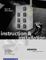
background image

instruction &

installation

GUIDE

Type WL
Switchgear

Low Voltage 
Metal-Enclosed 
Switchgear

Part # 11-C-9100-01 Rev. 1

Courtesy of NationalSwitchgear.com

Summary of Contents for 11-C-9100-01

Page 1: ...instruction installation GUIDE Type WL Switchgear Low Voltage Metal Enclosed Switchgear Part 11 C 9100 01 Rev 1 Courtesy of NationalSwitchgear com ...

Page 2: ...care and use of protective equipment such as rubber gloves hard hat safety glasses or face shields flash clothing etc in accordance with established safety practices c is trained in rendering first aid NOTE These instructions do not purport to cover all details or variations in equipment nor to provide for every possible contingency to be met in connection with installation operation or maintenanc...

Page 3: ...hipping Sections 15 Setting Shipping Sections 15 Leveling of the Switchgear 15 Leveling Indoor Switchgear 15 Leveling Outdoor Switchgear 15 Installation of Traveling Crane 16 Extension of Existing Switchgear 16 Extending Indoor Switchgear 16 Extending Outdoor Switchgear 16 Electrical Connections 17 21 Primary Connections 17 Bus Bars and Connectors 17 Bolted Bus Joints 17 Hardware Tightening Instru...

Page 4: ...indicate the degree of hazard that may be encountered by the user These words are defined as Danger Indicates an imminently hazardous situation which if not avoided will result in death or serious injury Warning Indicates a potentially hazardous situation which if not avoided could result in death or serious injury Caution Indicates a potentially hazardous situation which if not avoided may result...

Page 5: ...ipment furnished has been designed to operate in a system having the circuit capacity specified by the purchaser If for any reason the equipment is later used in a different sys tem or if the short circuit capacity of the system is increased the bus bracing momentary and short time ratings of the switchgear the interrupting capacity of the circuit breakers and the bus capacity must be checked Fail...

Page 6: ...eral arrangement drawing for location of each shipping section within a group lineup Use this information to simplify the assembly operation and avoid unnecessary handling Inspection and Unpacking Inspect the equipment as soon as possible after receiving for any damage that may have occurred in transit Before unpack ing examine the package itself as a damaged package may indicate an area of damage...

Page 7: ... Any adverse judgement as to whether the equipment was properly loaded or properly prepared by shipper for over the road travel cannot be made at the destination Shipments are not released from the factory without a clear bill of lading blocking and tarping of the equipment before it leaves the Siemens factory Therefore if the equipment is received in a damaged condition this damage to the equipme...

Page 8: ...gear with Rollers and Jacks Moving switchgear in an obstructed area where a crane cannot be employed can be accomplished by the use of rollers indoor enclosure only however this must be done before the wooden shipping skid is removed If pipes are used as rollers they should be of sufficient diameter that they will roll with ease without digging into the skid In placing rollers under the skid or re...

Page 9: ...ltage Metal Enclosed Switchgear Receiving Handling Storage Figure 4 Use of Jacks for Lifting Indoor Equipment Only Figure 5 Use of Rollers to Move Switchgear Indoor Enclosure Only 7 Courtesy of NationalSwitchgear com ...

Page 10: ... slid into place See Figure 6 Figure 6 Final Positioning of Switchgear in Obstructed Areas Without a Crane 8 Be sure to install roof channels on outdoor switchgear to make the equipment weather resistant See Figure 13 9 See installation section for additional important information Storage Indoor Switchgear When switchgear is not to be installed immediately it should be unpacked inspected within 15...

Page 11: ...lab it is highly recommended that 3 minimum sill channels be grouted into the floor as shown in Figure 7 The surface of the sills should be slightly above floor level The surfaces of the sills must be level and in the same horizontal plane within 1 16 1 6mm There should be no projection above the plane within the area covered by the switchgear If the floor or sills do not meet this requirement it ...

Page 12: ... be lower Indoor 22 wide with 4 breakers 2850 lbs 1300kg 32 wide with 2 breakers 3050 lbs 1385kg 32 wide with 1 breaker and fuse carriage 3150 lbs 1430kg Transition box 680 lbs 310kg Outdoor 22 wide with 4 breakers 4200 lbs 1910kg 32 wide with 2 breakers 4550 lbs 2070kg 32 wide with 1 breaker and fuse carriage 4650 lbs 2110kg Transition box 680 lbs 310kg These estimates should be increased for unu...

Page 13: ...32 59 828 OR 65 Fused with F Class Breakers Above 21 25 540 18 88 480 37 59 955 70 Non fused with N S H or L Class Breakers Below 31 50 800 13 88 353 32 59 828 OR 75 Fused with F Class Breakers Above 31 25 794 18 88 480 37 59 955 80 Non fused with Below 41 50 1054 13 88 353 32 59 828 N S H or L Class Breakers Above 41 25 1048 80 Fused with Below 36 50 927 18 88 480 37 59 955 F Class Breakers Above...

Page 14: ...Figure 10 Typical Indoor Side View Side View Equipment Depth Breaker Compartment Depth Rear Compartment Depth Anchor Bolt Spacing 60 1524 Non fused breakers 19 8 503 22 4 569 59 13 1502 65 1651 Fused breakers 24 8 630 22 4 569 64 13 1629 70 1778 Non fused breakers 19 8 503 32 4 823 69 13 1756 75 1905 Fused breakers 24 8 630 32 4 823 74 13 1883 80 2032 Non fused breakers 19 8 503 42 4 1077 79 13 20...

Page 15: ...re and if a deeper internal frame structure is used 65 or 75 the extra depth should be added to the 60 43 dimension 73 77 dimension is based on 60 internal frame structure and if a deeper internal frame structure is used 65 or 75 the extra depth should be added to the 73 77 dimension Outdoor Non Walk in Side View 60 is representative for a 60 deep switchgear internal structure For other internal s...

Page 16: ... extra depth should be added to the 60 43 dimension 102 2 dimension is based on 60 internal frame structure and if a deeper internal frame structure is used 65 or 75 the extra depth should be added to the 102 2 dimension Outdoor Walk in Side View 60 is representative for a 60 deep switchgear internal structure For other internal structure depths 65 or 75 add extra depth to 60 that is shown 103 8 i...

Page 17: ...or bolt locations as shown in Figures 9 10 11 and 12 Examine these anchor bolt locations to make certain that the section is in firm contact with the mounting surface in the area of the anchor bolt In the absence of firm contact shims must be added adjacent to the anchor bolt holes These shims will prevent distortion of the section when anchor bolts are drawn tight Shims should be approxi mately t...

Page 18: ...g Switchgear Provisions have been made for future extension of switchgear lineups The main bus has been terminated with silver plated copper pads with the necessary holes to splice to the new installation Extending Indoor Switchgear To extend indoor switchgear remove the end plate line up and anchor the new equipment as covered in the first part of this instruction book make up the primary and sec...

Page 19: ...normally is not necessary and should not be done unless parts are badly tarnished If cleaning is necessary use a mild cleaner and thoroughly rinse parts to remove all residue 3 Assemble all joints with parts dry Do not use any grease or oxide inhibiting compounds 4 Refer to Figures 16 17 and 18 for method of bolting joints and follow hardware tightening instructions which follow 5 Horizontal main ...

Page 20: ...TRIC VIEW BOLT REAR SECTION OF HORIZONTAL BUS TO C BEAM USING SPLICE PLATE AND SHIM PLATE AS REQUIRED RIGHT BUS SECTION SHOWN THROUGH BUS DOES NOT REQUIRE SHIM PLATE STEP 2 B PHASE BUS JOINT SHOWN A C PHASES SAME NOTE FULLY ASSEMBLED REAR ISOMETRIC VIEW BOLT HORIZONTAL BUS TO POWER CONNECTOR SUB ASSEMBLY USING SPLICE PLATE AND SHIM PLATE AS REQUIRED RIGHT BUS SECTION SHOWN THROUGH BUS DOES NOT REQ...

Page 21: ...S AS REQUIRED RIGHT BUS SECTION SHOWN THROUGH BUS DOES NOT REQUIRE SHIM PLATES STEP 1 REAR ISOMETRIC VIEW REAR ISOMETRIC VIEW BOLT REAR SECTION OF HORIZONTAL BUS DOUBLE BAR TO C BEAM USING SLICE PLATE AND SHIM PLATES DOUBLE THICKNESS AS REQUIRED RIGHT BUS SECTION SHOWN THROUGH BUS DOES NOT REQUIRE SHIM PLATES STEP 2 B PHASE BUS JOINT SHOWN A C PHASES ASSEMBLE SAME NOTE FULLY ASSEMBLED REAR ISOMETR...

Page 22: ...e shipped with flexible connectors attached to either the switchgear assembly or the transformer assembly The flexible connectors contain the required hardware to make the connections to the transformer terminals Carefully observe how the flexible connectors are mounted to the switchgear placement of bolts nuts washers and spacers then remove the flexible connectors or carefully spread them to pre...

Page 23: ...rmers for metering are generally mounted on the stationary primary disconnect studs in the circuit breaker compartment and are readily accessible for inspection and replacement Current transformers for electronic trip device use are called tripping transformers They are mounted in the circuit breaker except when a ground fault trip element or neutral metering element is furnished for a four wire a...

Page 24: ...It is not expected that equipment shall be subjected to these tests after it has been stored for long periods of time or has accumulated a large amount of dust moisture or other contaminants without being first restored to good condition 3 With circuit breaker in the TEST position make the following tests on each unit A Trip and close the circuit breaker manually and electri cally if breaker is el...

Page 25: ...ncoming power source to equipment 3 Check all instruments relays meters etc during this time 4 Connect as small a load as possible and observe instruments Note Allow several minutes before connecting additional load 5 Gradually connect more load to the equipment while observing instruments until the full load is connected 6 Check for overheating of primary and secondary circuits and satisfactory o...

Page 26: ...include all the tasks shown in Table 1 Table 1 Maintenance Tasks WARNING Failure to properly maintain the equipment can result in death serious injury or product failure and can prevent successful functioning of connected apparatus The instructions contained herein should be carefully reviewed understood and followed The maintenance tasks in Table 1 must be performed regularly 1 Before any mainten...

Page 27: ...and secondary disconnects when properly lubricated will greatly outwear contacts without grease and will be protected from severe tarnishing After wiping off old grease apply a thin film of electrical contact lubricant 11 B 9824 periodically Avoid getting contact lubricant on insulating materials Electrical contact lubricant should be applied to 1 Primary disconnects 2 Secondary disconnects In ext...

Page 28: ...h maintenance inspection all of the old grease should be wiped off of the contacts and new lubricant applied to all sliding surfaces Apply the material in a layer 03 06 1 2mm thick Use only Siemens Electrical Contact Lubricant Part No 11 B 9824 Other exposed components can be protected with a coat of glyptol or other corrosion resistant coating When old grease becomes dirty wipe the part clean and...

Page 29: ...com power Order LVBR 02000 0404 New 0404B A 2004 Siemens Energy Automation Inc All Rights Reserved Siemens is a registered trademarks of Siemens AG Product names mentioned may be trademarks or registered trademarks of their respective companies Specifications are subject to change without notice Courtesy of NationalSwitchgear com ...

Reviews: