background image


SV2414 / SVL2416 

MAINTENANCE MANUAL 


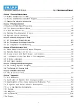
Summary of Contents for SV2414

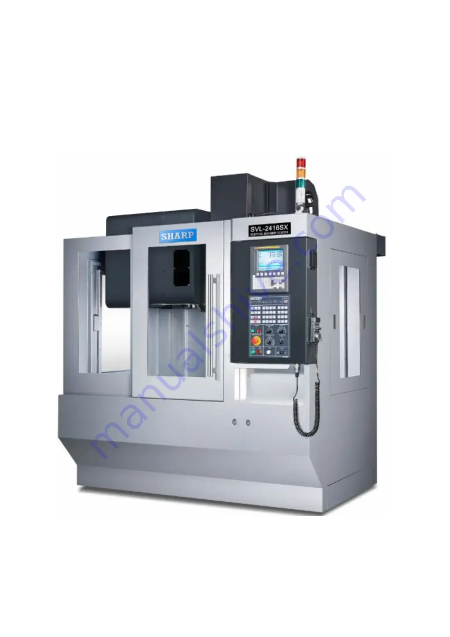
Page 1: ...SV2414 SVL2416 MAINTENANCE MANUAL ...

Page 2: ...ing 26 Chapter 4 The Lubrication Unit 4 1 Centralized Lubrication System Diagram 28 4 2 Spindle Bearing Lubrication 30 4 3 Guide ways and Ball Screw Lubrication 30 4 4 Lubrication of the Cam Box of Tool Magazine 34 4 5 Cylinder Lubrication 35 4 6 Lubrication Location 35 Chapter 5 The Spindle Oil Cooling Unit 5 1 Oil Cooling Pipeline Diagram 38 5 2 The Spindle Oil Cooling Unit 39 Chapter 6 The Elec...

Page 3: ...PRECISION MACHINE TOOLS Ver 1 Maintenance Manual 3 7 5 5 Spindle base work bench 128 7 5 6 Base plate 130 ...

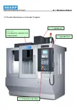
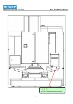
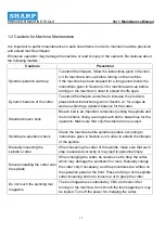
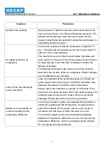
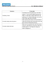
Page 4: ...PRECISION MACHINE TOOLS Ver 1 Maintenance Manual 4 Chapter 1 Routine Maintenance ...

Page 5: ... Clean A Adjustment F Function check G Grease coasting R Replace when necessary No Maintenance Daily Weekly Monthly Annually Note 1 Spindle operation warm up 2 Spindle unit Spindle nose 3 Lubrication pump Depending on the brand of the lube oil 4 Lubrication unit Lubrication pump oil volume 5 Spindle oil coolant unit 6 Temperature difference setup 1 C 7 Spindle oil coolant unit Oil coolant unit fil...

Page 6: ...Operation button F 18 Spindle cooling fan 19 Electric box CNC axial battery R 20 Machine static precision check A 21 Machine position precision check A Replace 22 Oil skimmer F Note The schedule presented in table is for normal operation only If the environment is not optimal or if the usage frequency has exceeded the suggested basic standard you may need to increase the frequency of maintenance N...

Page 7: ...PRECISION MACHINE TOOLS Ver 1 Maintenance Manual 7 1 2 Routine Maintenance Instruction Diagram 14 15 Tool magazine Automatic tool change system 1 2 Spindle unit 17 Operation box 16 Emergency stop button ...

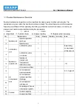
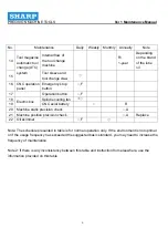
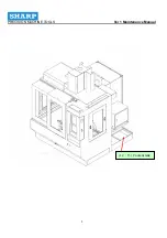
Page 8: ...PRECISION MACHINE TOOLS Ver 1 Maintenance Manual 8 12 13 Coolant tank ...

Page 9: ...PRECISION MACHINE TOOLS Ver 1 Maintenance Manual 9 Machine precision check 20 21 ...

Page 10: ...PRECISION MACHINE TOOLS Ver 1 Maintenance Manual 10 18 19 Electrical box 23 Oil skimmer 8 9 10 11 Air compressor preparation unit 3 4 Central lubrication system ...

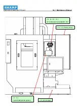
Page 11: ...PRECISION MACHINE TOOLS Ver 1 Maintenance Manual 11 5 6 7 Spindle oil temperature controller ...

Page 12: ...dard broach bolts Broach bolt is an important component jointing the spindle and the tool shank Using a wrong broach bolt is hazardous for the operation Make sure that only the standard one is used Spindle pre operation check Check the machine before spindle operation according to instructions given in Section 2 4 in order to extend the lifespan of the spindle Manually loosening the spindle s cutt...

Page 13: ... tank of the air compressor Water drainage is more effective in the morning Lube oil from the lubricating pump automatic Lube oil is released by the lubricating pump to lubricate the guide ways and the lead screws Insufficient lubrication may speed up the abrasion and affect machine precision Always make sure that there is enough oil in the tank If the amount of oil is below the lower limit of the...

Page 14: ...de ways To extend the lifespan remove the dust or they may scratch the slide Correctly locking the work pieces When placing work pieces onto the workbench make sure that they are well locked or they may spin out and cause personnel injury Correctly locking the doors Make sure the operation door and the two side doors are well locked to prevent the cutter from bursting apart or iron filings from fl...

Page 15: ...PRECISION MACHINE TOOLS Ver 1 Maintenance Manual 15 Chapter 2 The Spindle Unit ...

Page 16: ...of the spindle and weight of the shank Therefore using a shorter cutter with a smaller diameter for high speed chipping is advantageous in terms of spindle vibration temperature increase thermal deformation and processing precision 4 The geometric shape of the cutter blade has an effect on cutter abrasion Increase the angular backlash of the blade can reduce abrasion due to scratches Suitable cutt...

Page 17: ...PRECISION MACHINE TOOLS Ver 1 Maintenance Manual 17 2 2 Tool Shank and Broach Bolts ...

Page 18: ...PRECISION MACHINE TOOLS Ver 1 Maintenance Manual 18 CAT 40 STUD ...

Page 19: ...eck Contents 1 Routine operation Max Rpm 20 10 1 Less than 10 C increase of temperature 2 Shocks 3 Noises 2 If the spindle has been stopped for more than two hours warm up is compulsive 20 10 1 Less than 10 C increase of temperature Shocks 2 Noises 3 Spindle stopped for more than 72 hours 1 20 2 50 10 10 1 Less than 10 C increase of temperature 2 Shocks 3 Noises 4 Spindle stopped for more than 2 w...

Page 20: ...stalled onto the spindle do not operate the spindle See the figure below If the temperature of the bearing has increased for more than 10 reduce the rotation speed of the spindle to 500 and do not carry out the warm up until the temperature is about 5 C higher than the room temperature ...

Page 21: ... of the maximum speed The machine has to have a forced warm up for 10 minutes before starting the actual work 5 Do not adjust the oil air mixing valve Use the factory set default value for lubrication interval Do not change the values arbitrarily or the bearing may be damaged 6 For this unit if the screen displays ALARM 1002 1056 2004 check and turn off the alarm before continuing the operation 7 ...

Page 22: ... is blocked the screen will display ALARM 1002 3 The third spindle protection is the pressure switch for air pressure supply If there is insufficient air pressure the mixing valve will be incapable of emitting the oil aerosol If this ALARM goes off check whether the oil pipeline is broken and whether air pressure supply is sufficient 4 If the clients still cannot turn off the alarm after checking ...

Page 23: ...PRECISION MACHINE TOOLS Ver 1 Maintenance Manual 23 Chapter 3 The Air Compressor Unit ...

Page 24: ...PRECISION MACHINE TOOLS Ver 1 Maintenance Manual 24 3 1 Air Compressor System Layout ...

Page 25: ...PRECISION MACHINE TOOLS Ver 1 Maintenance Manual 25 ...

Page 26: ... water drainage the machine operator should check whether there is any water accumulation at the shift or at the end of the day If the water drainage function is abnormal water vapor may get into the air compressor component thereby reducing the lifespan For the water drainage function of the filter to be more effective water in the air tank of the air compressor should fully drained out It is als...

Page 27: ...leakage at the screw cap 1 Loosened cap nut 2 Broken film 1 Tighten the cap nut 2 Replace the film No oil dripped from the oil cup 1 The adjusting needle being too tight 2 The adjusting needle cannot be closed or there are dirts on the needle The adjustment needle cannot bear the pressure 3 Broken or damaged adjusting needle or needle base 1 Loosen up the needle 2 Reduce the oil volume until the l...

Page 28: ...PRECISION MACHINE TOOLS Ver 1 Maintenance Manual 28 Chapter 4 The Lubrication Unit ...

Page 29: ...er 1 Maintenance Manual 29 4 1 Centralized Lubrication System Diagram 1 Components of the lubrication oil pump a Flow rate 300cc min b Voltage 220V 50 60 HZ c Power 150W d Maximum output pressure 15kg cm e Oil tank capacity 6L ...

Page 30: ...ual 30 2 Lubrication System Diagram Number Model Name Quantity 1 PA6 Pipe cape 3 2 PB6 Pipe 3 3 PKD6 3 way pipe 1 4 PH601 Right angle connector 2 Connections 1 3 Electric source 2 3 Manual oil injection 4 5 Floating switch 6 7 Pressure in section ...

Page 31: ... therefore there is no need to add or to change the lube oil for a while It is therefore cost saving 4 3 Guide way and Ball Screw Lubrication The linear guide way of X Y and Z axes and the ball screws are lubricated by a centralized lubrication system which lubricates according to the set schedule Machine operators must ensure that the oiling machine has enough oil as well as whether there is any ...

Page 32: ... procedure Repeat this process until lube oil has leaked out from the guide way Cautions The oil tank has a 6 L capacity Add oil from the oil inlet each week or when necessary If the oil level reaches the minimum oil level the operation panel will issue an alarm message informing the risk 1 Add clean lube oil specified for the guide way through the oil inlet Do not use other types of lube oil The ...

Page 33: ...PRECISION MACHINE TOOLS Ver 1 Maintenance Manual 33 SPINDLE HEAD UNIT WORK TABLE UNIT ...

Page 34: ...PRECISION MACHINE TOOLS Ver 1 Maintenance Manual 34 Saddle unit ...

Page 35: ...raight angle connector 17 10 PH601 Straight angle connector 2 11 HBL 3 Volume based distributor 1 12 PQ101 Connector 2 13 PG01 Sealing plug 1 4 4 Lubrication of the Cam Box of Tool Magazine Tool magazine s rotation is driven by ACT cam box To ensure a smooth rotation of the cam box it has to be routinely checked on whether there is enough oil for the oil lens If not add oil After 2 400 hour of ope...

Page 36: ...hine maintenance dot not disassemble the oil cup or it may be damaged 3 The color of the oil will be darkened if it has not been replaced for a long time It will affect the air pressure and lifespan of the machine Check it routinely or monthly 4 It is abnormal is the oil is depleted within 2 to 3 days Check whether there is leakage at the oil cup or the cup is broken If so replace the oil cup If t...

Page 37: ...PRECISION MACHINE TOOLS Ver 1 Maintenance Manual 37 4 6 Lubrication Location ...

Page 38: ...PRECISION MACHINE TOOLS Ver 1 Maintenance Manual 38 Chapter 5 The Spindle Oil Cooling Unit ...

Page 39: ...PRECISION MACHINE TOOLS Ver 1 Maintenance Manual 39 5 1 Oil Cooling Pipeline Diagram ...

Page 40: ... correct type of oil according to the instructions presented on the plaque b The air filter of the cooling unit should be kept clean It can be taken out for cleaning c The cooling unit also has a oil filter which has to be cleaned routinely Names and operation of functions on the small panel ...

Page 41: ... the SV is set to temperature of the oil will be greater than of machine When the SV is set to temperature of the oil will be less than of the machine In general these two temperatures are set to be equal If the oil temperature is set to be lower than the machine temperature temperature of the oil tank will be smaller than that of the machine In this case condensation may occur which could contami...

Page 42: ...PRECISION MACHINE TOOLS Ver 1 Maintenance Manual 42 ...

Page 43: ...r lamp is lighted up see figure 1 2 Check that electrical resistance of compressor and pump is above 500 ohms 3 Check that the oil level is at least at 80 level of the oil tank see figure 2 4 Check that the outlet of the oil tank is tightly secured 5 Check that the overload switch is at on position 6 Check that value is set at 5 kg cm for the pump pressure 5kg cm indicates 12 L min 20L min 30l min...

Page 44: ...PRECISION MACHINE TOOLS Ver 1 Maintenance Manual 44 ...

Page 45: ...running cooler can not reach to the setting temperature and working machine s spindle is hot If the above situation occurred please call professional technical staff to dispose or contact us directly Oil tank and filter 1 Oil level in tank should be ay least at the 80 level mark to prevent the air into the pump At the same time maintain the oil is clean 2 The oil filter must be replaced or cleaned...

Page 46: ... 7 Adjust oil pressure switch DIFF 0 3 kgf cm range 0 8 0 8 cmHg PUMP is lighted 1 Overload relay is off 2 Pump switch is off 3 Inlet pipe is clogged 1 Reset switch 2 Reset pump switch Clean pipe and replace oil filter COM is lighted 1 Overload relay off 2 Compressor breakdown 1 Reset switch 2 Replace compressor HP is lighted 1 Condenser is too dirty 2 Air filter is not clean 3 Cooling fan doesn t...

Page 47: ...PRECISION MACHINE TOOLS Ver 1 Maintenance Manual 47 Chapter 6 The Electrical Unit ...

Page 48: ...e five basic rules below 1 Only people know about this machine and have qualification as well as permission can operate the machine or performance the maintenance Those competent individuals have to receive appropriate training to understand the safety and protective measures as well as machine maintenance work These individuals have to be approved for their safety control ability Especially those...

Page 49: ...ys b The dust pan has two security keys To prevent the memory to be modified arbitrarily use the function showed on the right figure Emergency stop Press this button to halt the operation immediately Memory edit lock This key is used to prevent unauthorized or arbitrarily changing of the processing procedure ...

Page 50: ... The functions are presented on the right figure c Keep the user s manual at an easily accessed location If the manual word can t read please call the agent and confirm the model as well as the model number of the machine Main power switch Before performing and maintenance repair or for any emergency condition turn of this switch Locked electrical box The box cannot be opened by unauthorized perso...

Page 51: ...PRECISION MACHINE TOOLS Ver 1 Maintenance Manual 51 Chapter 7 Appendix ...

Page 52: ...scosity ISO VG68 2 Anti rust foam oxidation and emulsification 1 High thermal conduction 2 Good lubrication Lubrication Methods Oil feeder Automatic centralized lubrication Circulation Oil replacement interval When needed When needed Add more when needed replace the oil every year When needed Tank capacity 55CC 3L 270L Recommended Brands 1 MOBIL RARUS 424 2 ESSO TERESSO S32 3 CASTROL HYSPIN VG32 4...

Page 53: ...ange the positive and negative move distance of the Z axis to 99999999 and 99999999 Afterward return the Z axis to zero position Put a cutter on the spindle Measure 0 6 0 8 mm the distance of tool unclamp Then remove the cutter 2 Lock the tool calibration magazine module onto the body of the tool magazine Tool magazine calibration module Adjustment block ...

Page 54: ...e dial indicator to measure the position of the arm of the cutter The X axis deviation should not exceed 0 1mm 5 Fasten the screws circled by a red line according to the ISO standard 6 Hammer the tool magazine into the fixing pin circled by a yellow line Dial indicator Arm Modular concentricity test gauge Gripper Fixing screw for the tool magazine Fixing pin for the tool magazine Fixing screw for ...

Page 55: ...is from the nose end of the spindle to a position that is 100mm above the workbench See the figure below 2 1 Treat this position as the origin Zero the value corresponded to the Z axis on the screen 2 Shift the Z axis to a position where the corresponding position on the screen is 560mm Nose end of the spindle 100mm ...

Page 56: ...PRECISION MACHINE TOOLS Ver 1 Maintenance Manual 56 4 At this point the relative distance between the spindle nose end and the workbench is 560mm See the figure below 560 mm ...

Page 57: ...mode and look for 1815 Change the APZ of the Z axis to 0 before turning on the machine 5 After turning on the machine enter Parameter 1815 to change APZ of Z axis to 1 Turn on the machine again At this point the position of the Z axis will be treated as the machine reference point ...

Page 58: ...PRECISION MACHINE TOOLS Ver 1 Maintenance Manual 58 7 4 Descriptions on Program and Servo Alarms ...

Page 59: ...PRECISION MACHINE TOOLS Ver 1 Maintenance Manual 59 ...

Page 60: ...PRECISION MACHINE TOOLS Ver 1 Maintenance Manual 60 ...

Page 61: ...PRECISION MACHINE TOOLS Ver 1 Maintenance Manual 61 ...

Page 62: ...PRECISION MACHINE TOOLS Ver 1 Maintenance Manual 62 ...

Page 63: ...PRECISION MACHINE TOOLS Ver 1 Maintenance Manual 63 ...

Page 64: ...PRECISION MACHINE TOOLS Ver 1 Maintenance Manual 64 ...

Page 65: ...PRECISION MACHINE TOOLS Ver 1 Maintenance Manual 65 ...

Page 66: ...PRECISION MACHINE TOOLS Ver 1 Maintenance Manual 66 ...

Page 67: ...PRECISION MACHINE TOOLS Ver 1 Maintenance Manual 67 ...

Page 68: ...PRECISION MACHINE TOOLS Ver 1 Maintenance Manual 68 ...

Page 69: ...PRECISION MACHINE TOOLS Ver 1 Maintenance Manual 69 ...

Page 70: ...PRECISION MACHINE TOOLS Ver 1 Maintenance Manual 70 ...

Page 71: ...PRECISION MACHINE TOOLS Ver 1 Maintenance Manual 71 ...

Page 72: ...PRECISION MACHINE TOOLS Ver 1 Maintenance Manual 72 ...

Page 73: ...PRECISION MACHINE TOOLS Ver 1 Maintenance Manual 73 ...

Page 74: ...PRECISION MACHINE TOOLS Ver 1 Maintenance Manual 74 ...

Page 75: ...PRECISION MACHINE TOOLS Ver 1 Maintenance Manual 75 ...

Page 76: ...PRECISION MACHINE TOOLS Ver 1 Maintenance Manual 76 ...

Page 77: ...PRECISION MACHINE TOOLS Ver 1 Maintenance Manual 77 ...

Page 78: ...PRECISION MACHINE TOOLS Ver 1 Maintenance Manual 78 ...

Page 79: ...PRECISION MACHINE TOOLS Ver 1 Maintenance Manual 79 ...

Page 80: ...PRECISION MACHINE TOOLS Ver 1 Maintenance Manual 80 ...

Page 81: ...PRECISION MACHINE TOOLS Ver 1 Maintenance Manual 81 ...

Page 82: ...PRECISION MACHINE TOOLS Ver 1 Maintenance Manual 82 ...

Page 83: ...PRECISION MACHINE TOOLS Ver 1 Maintenance Manual 83 ...

Page 84: ...PRECISION MACHINE TOOLS Ver 1 Maintenance Manual 84 ...

Page 85: ...PRECISION MACHINE TOOLS Ver 1 Maintenance Manual 85 ...

Page 86: ...PRECISION MACHINE TOOLS Ver 1 Maintenance Manual 86 ...

Page 87: ...PRECISION MACHINE TOOLS Ver 1 Maintenance Manual 87 ...

Page 88: ...PRECISION MACHINE TOOLS Ver 1 Maintenance Manual 88 ...

Page 89: ...PRECISION MACHINE TOOLS Ver 1 Maintenance Manual 89 ...

Page 90: ...PRECISION MACHINE TOOLS Ver 1 Maintenance Manual 90 ...

Page 91: ...PRECISION MACHINE TOOLS Ver 1 Maintenance Manual 91 ...

Page 92: ...PRECISION MACHINE TOOLS Ver 1 Maintenance Manual 92 ...

Page 93: ...PRECISION MACHINE TOOLS Ver 1 Maintenance Manual 93 ...

Page 94: ...PRECISION MACHINE TOOLS Ver 1 Maintenance Manual 94 ...

Page 95: ...PRECISION MACHINE TOOLS Ver 1 Maintenance Manual 95 ...

Page 96: ...PRECISION MACHINE TOOLS Ver 1 Maintenance Manual 96 ...

Page 97: ...PRECISION MACHINE TOOLS Ver 1 Maintenance Manual 97 ...

Page 98: ...PRECISION MACHINE TOOLS Ver 1 Maintenance Manual 98 ...

Page 99: ...PRECISION MACHINE TOOLS Ver 1 Maintenance Manual 99 ...

Page 100: ...PRECISION MACHINE TOOLS Ver 1 Maintenance Manual 100 ...

Page 101: ...PRECISION MACHINE TOOLS Ver 1 Maintenance Manual 101 ...

Page 102: ...PRECISION MACHINE TOOLS Ver 1 Maintenance Manual 102 ...

Page 103: ...PRECISION MACHINE TOOLS Ver 1 Maintenance Manual 103 ...

Page 104: ...PRECISION MACHINE TOOLS Ver 1 Maintenance Manual 104 ...

Page 105: ...PRECISION MACHINE TOOLS Ver 1 Maintenance Manual 105 ...

Page 106: ...PRECISION MACHINE TOOLS Ver 1 Maintenance Manual 106 ...

Page 107: ...PRECISION MACHINE TOOLS Ver 1 Maintenance Manual 107 ...

Page 108: ...PRECISION MACHINE TOOLS Ver 1 Maintenance Manual 108 ...

Page 109: ...PRECISION MACHINE TOOLS Ver 1 Maintenance Manual 109 ...

Page 110: ...PRECISION MACHINE TOOLS Ver 1 Maintenance Manual 110 ...

Page 111: ...PRECISION MACHINE TOOLS Ver 1 Maintenance Manual 111 ...

Page 112: ...PRECISION MACHINE TOOLS Ver 1 Maintenance Manual 112 ...

Page 113: ...1 SVL2416SX Item NAME Qty 1 Shaft 1 2 Spindle Body 1 3 Collar 1 4 Collar 1 5 Collar 1 6 Collar 1 7 Front Cover 1 8 Jacketing 1 9 Nut 1 10 Pull Stud 1 11 Coupling 1 12 Spring collar 1 13 Shaft bar 1 14 Cylinder seat 1 15 Shaft stopper 1 16 Round Key 2 17 Tac bearing 4 18 Nut 1 19 Cylinder 1 20 Coupling 1 ...

Page 114: ...PRECISION MACHINE TOOLS Ver 1 Maintenance Manual 114 7 5 2 Tool Magazine 1 Umbrella type ...

Page 115: ...PRECISION MACHINE TOOLS Ver 1 Maintenance Manual 115 ...

Page 116: ... M6 1 0P 12L 2 12 Sensor 3RG4012 0AB00 2 13 PVC Wave tube connection 3 4 2 14 Support 1 15 Hex socket screw M8 1 25P 40L 8 16 Slide seat guard cover 724L 1 17 Slide seat 1 18 Tool magazine cover 420H 1 19 Flat head inside hex socket screw M5 0 8P 14L 3 20 Safety door 1 21 Bevel pin Φ10 38L 2 22 Hex socket screw M10 1 5P 55L 4 23 Fixing shaft 1 24 Lower press plate 1 25 Hex socket screw M8 1 25P 20...

Page 117: ... 1 75P 110L 1 41 Cover 1 42 Bearing locking nut AN05 1 43 Ball thrust bearing BMW51105 2 44 Rocking arm 1 45 Spacer ring 1 46 Rocking arm 1 47 Hex socket screw M5 0 8P 25L 4 48 Connecting rod 1 49 The bearing of handles CF8 1 50 Cam plate 1 51 PVC Wave tube 3 4 1 52 Flat washer M6 7 53 Hex socket screw M6 1 0P 20L 3 54 Number plate 20 55 Hold tool carrier Option 20 56 Flat washer MT420H 20 57 Hex ...

Page 118: ... switch seat 2 70 Spacer MT420 MT424 1 71 Spring washer M8 1 72 Stoppage screw M5 0 8P 8L 40 83 Sleeve 1 74 Flat washer M6 14 75 Spring washer M8 4 76 Hex socket screw M6 1 0P 20L 4 77 Spring washer M4 5 78 Flat washer M4 5 79 Spring washer M6 29 80 Hex socket screw M6 85L 4 81 Flat washer M6 13 1 4 82 Spring washer M12 3 83 Suns nut M12 2 84 Hex Nut M12 2 85 Semicircle key 4 4 25L 1 86 Chain 320 ...

Page 119: ...nside hex screw M4 0 7P 8L 5 95 Hex socket screw M4 0 7P 25L 4 96 Stoppage screw M8 1 25P 14L 2 97 Flat washer M6 20 98 Flat head inside hex socket screw M5 0 8P14L 40 99 Spring washer M6 4 100 Ring M12 2 101 Plastic connection 2 102 Tube connection CTL 1003A 2 103 Hex Nut M8 1 104 Flat washer M12 0 105 Protect seat 1 106 Motor screw M2 5 4 107 Make No plate 1 108 Dividing plate cover 1 ...

Page 120: ...PRECISION MACHINE TOOLS Ver 1 Maintenance Manual 120 ...

Page 121: ...PRECISION MACHINE TOOLS Ver 1 Maintenance Manual 121 ...

Page 122: ...13 Nut M10x1 5P 24 14 Plain Washer M6 32 15 Spring Washer M6 36 16 Hexagon Socket Button Head Screw M6x1 0Px20L 8 17 Straight Pin ψ10x38L 5 18 Nut M14x1 5P 2 19 Cylinder Mounting Plate Module 1 20 Hexagon Socket Button Head Screw M8x1 25Px40L 8 21 Limit Switch Bracket 2 22 Hexagon Socket Button Head Screw M5x0 8Px10L 13 23 Rod 1 24 Limit Switch SHL Q2255 2 25 Plain Washer M4 24 26 Retaining Ring C...

Page 123: ...150Px50L 24 45 Hexagon Socket Button Head Screw M4x0 7Px8L 24 46 Name plate 24 47 Tool Mounting block 24 48 Socket Countersunk Head Screw M4x0 7Px8L 24 49 PVC Joints HE 1 ψ28 1 50 Tool Tilt Block 1 51 Tool Roller 24 52 Tool Roller Pin 24 53 Retaining Ring C S 10 48 54 ATC Cover 1 55 Magazine Adjustiment Block 1 56 Hexagon Socket Button Head Screw M6x1 0Px16L 14 57 Sensor 3RG4012 OAF01 PNP 2 58 Cam...

Page 124: ... 76 Cap Scar 2 77 Key 2 78 Socket Countersunk Head Screw M5x0 8Px14L 2 79 Sensor Bracket 1 80 Cam mounted plate 81 Hexagon Socket Button Head Screw M10x1 5Px35L 1 82 Hook Ring 6 83 Taper Roller Bearing 1 84 Cam 1 85 Washer AW06 1 86 Locking Nut AN06 1 87 Roller Cam 1 88 Key 8x10x70L 1 89 Key 5x5x25L 1 90 Gear Mounted plate 2 91 Gear 2 92 Taper Roller Bearing 32005 2 93 Washer AW05 1 94 Locking Nut...

Page 125: ...on Socket Button Head Screw M6x1 0Px25L 24 107 Steel Ball 8mm 96 108 Hexagon Socket Button Head Screw M10x1 5Px8L 96 109 Spring ψ1 2xcd8x14xn6 96 110 Hexagon Socket Button Head Screw M6x1 0Px8L 8 111 Position pin 24 112 Hexagon Socket Button Head Screw M10x1 5Px30L 4 113 Retaining Ring C S8 2 114 Cylinder Mounting Adapter plate 1 115 Nut M12 4 116 Sensor Dog 1 117 Hexagon Socket Button Head Screw ...

Page 126: ...ME Size Qty 1 Main bracket 1 2 Spindle ψ120 1 3 Hexagonal Socket Head Screw M8x1 25Px40L 6 4 Spindle Adapter Plate 1 5 Hexagonal Socket Head Screw M12x1 75Px35L 4 6 Motor adjustment plate 1 7 Hexagonal Socket Head Screw M10x1 5Px50L 4 8 Hexagonal Socket Head Screw M8x1 25Px30L 16 ...

Page 127: ...PRECISION MACHINE TOOLS Ver 1 Maintenance Manual 127 7 5 4 Column 1 SVL2416 ...

Page 128: ...imension ψ20xψ35 inside 1 11 Z Motor plate Cover 1 12 Stainless Hexagonal Socket Head Screw M4x0 7Px6L 4 13 Z Bearing Case 1 14 Hexagonal Socket Head Screw M10x1 15Px35L 4 15 Ball Screw R32 16K4 FSC 626 790 0 008 1 16 Ball Bearing NTN 6205ZZC2 2AS 1 17 Retaining Ring C S25 1 18 Stopper T 25 2 19 Hexagonal Socket Head Screw M6x1 0Px35L 2 20 Stopper T 15 2 21 Hexagonal Socket Head Screw M6x1 0Px16L ...

Page 129: ...PRECISION MACHINE TOOLS Ver 1 Maintenance Manual 129 7 5 5 Base Plate 1 SVL2416 ...

Page 130: ...10 10 Taper Pin ψ8x40L 6 11 Y Bearing Case T 50mm 1 12 Ball Screw Nut Plate 115L 1 13 Ball Screw R32 16K4 FSC 626 790 0 008 1 14 Ball Bearing NTN 6205ZZC2 2AS 1 15 Retaining Ring C S25 1 16 Y Bearing Case Cover 1 17 Hexagonal Socket Head Screw M4x0 7Px6L 4 18 Stopper T 25 2 19 Stopper T 40 2 20 Hexagonal Socket Head Screw M6x1 0Px35L 2 21 Hexagonal Socket Head Screw M6x1 0Px25L 8 22 Coupling ψ65 o...

Page 131: ...PRECISION MACHINE TOOLS Ver 1 Maintenance Manual 131 7 5 6 Saddle base Workbench 1 SVL2416 ...

Page 132: ...75Px45L 4 11 Ball Bearing NTN 6205ZZC2 2AS 1 12 Retaining Ring C S25 1 13 Table W 30 1 14 Ball Screw Nut Plate X Axis 1 15 Hexagonal Socket Head Screw M10x1 5Px35L 4 16 Ball Screw R32 16K4 FSC 786 950 0 008 1 17 Hexagonal Socket Head Screw M10x1 5Px25L 16 18 Stopper T 25 2 19 Stopper T 20 2 20 Hexagonal Socket Head Screw M6x1 0Px35L 4 21 Coupling ψ65 outside dimention ψ20xψ35 inside 1 22 X Motor m...

Reviews: