Sharp RK-12S30, Installation Instructions Manual
The Sharp RK-12S30 is a state-of-the-art kitchen appliance that requires precise installation. Make sure to access its comprehensive Installation Instructions Manual, available for free download from manualshive.com. This detailed manual provides step-by-step guidance, ensuring a trouble-free setup and efficient operation of your Sharp RK-12S30.
Share
Download


Reviews:
No comments
Related manuals for RK-12S30

JEM31WF - Spacemaker II Microwave Oven
Brand: GE Pages: 4

2115WCOL
Brand: U-Line Pages: 4

NNC994S - Genius Prestige - Convection Microwave...
Brand: Panasonic Pages: 1

OKO-CENTER 1
Brand: Würth Pages: 2

COB-H
Brand: Broil King Pages: 2

Marble + Brass 2743412
Brand: West Elm Pages: 3
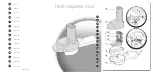
Fresh Express Mov'
Brand: Moulinex Pages: 40

FP-SP
Brand: Cuisinart Pages: 20
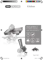
Kitchen meat grinder
Brand: OBH Nordica Pages: 24
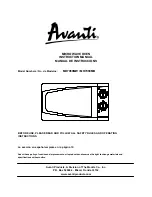
MO7080MW
Brand: Avanti Pages: 28
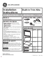
JX1095STBB
Brand: GE Pages: 12
32507S
Brand: Hamilton Beach Pages: 10

MASTERCHEF PSC-150/SM
Brand: Sam Cook Pages: 34
155371
Brand: Russell Hobbs Pages: 72

AC110 series
Brand: Jenn-Air Pages: 16

PSC-150/PM
Brand: Sam Cook Pages: 30
H6.2542
Brand: V-ZUG Pages: 11
155372
Brand: Russell Hobbs Pages: 48


