background image

DATA PROJECTOR

MODEL

XG-C465X-L
XG-C435X-L

OPERATION MANUAL

Intr

oduction

Quic

k Star

t

Setup

Connections

Basic Operation

Useful Features

Appendix

Summary of Contents for Notevision XG-C435X-L

Page 1: ...DATA PROJECTOR MODEL XG C465X L XG C435X L OPERATION MANUAL Introduction Quick Start Setup Connections Basic Operation Useful Features Appendix ...

Page 2: ...is marked with the letter N or coloured black The wire which is coloured brown must be connected to the terminal which is marked with the letter L or coloured red IF YOU HAVE ANY DOUBT CONSULT A QUALIFIED ELECTRICIAN The supplied CD ROM contains operation instructions in English German French Spanish Italian Dutch Swedish Portuguese Chinese Korean and Arabic Carefully read through the operation in...

Page 3: ...gle is intended to alert the user to the presence of uninsulated dangerous voltage within the product s enclosure that may be of sufficient magnitude to constitute a risk or electric shock to persons The exclamation point within a triangle is intended to alert the user to the presence of important operating and maintenance servicing instructions in the literature accompanying the product Introduct...

Page 4: ... acceptable tolerances which may result in inactive dots on the picture screen This will not affect the picture quality or the life expectancy of the unit Microsoft and Windows are registered trademarks of Microsoft Corporation in the United States and or other countries PC AT is a registered trademark of International Business Machines Corporation in the United States Adobe Reader is a trademark ...

Page 5: ...em Picture Mode Contrast 0 0 0 0 Bright Color Tint 0 Sharp Standard 7500K 3D Progressive Auto Off Off Off SEL ADJ RETURN ENTER END Picture SIG SCR PRJ Net 0 0 Red Blue CLR Temp Progressive Film Mode DNR MNR Eco Quiet Mode Reset How to Read this Operation Manual In this operation manual the illustrations and on screen displays are simplified for explana tion This may differ from the actual on scree...

Page 6: ...3 Checking the Lamp Life Status 53 Setting up the Projector Network Environment Network menu 54 Setting a Password 54 DHCP Client Setting 55 TCP IP Setting 55 Confirming the Projector Information 55 Introduction How to Read this Operation Manual 3 Contents 4 How to Access the PDF Operation Manuals 6 IMPORTANT SAFEGUARDS 7 Accessories 10 Part Names and Functions 12 Using the Remote Control 15 Usabl...

Page 7: ...roubleshooting 66 For SHARP Assistance 68 Specifications 69 Index 70 SETUP MANUAL Refer to the SETUP MANUAL contained on the supplied CD ROM for details Setting up the Screen 2 Screen Size and Projection Distance 3 Changing the Lens 9 Connecting Pin Assignments 11 RS 232C Specifications and Commands 13 Setting up the Projector Network Environment 18 Controlling the Projector via LAN 24 Setting up ...

Page 8: ...he setup manual 1 Double click the SETUP folder 2 Double click the language name of the folder that you want to view 3 Double click the pdf file to access the setup manual For Macintosh 1 Insert the CD ROM in the CD ROM drive 2 Double click the CD ROM icon 3 When you want to view the operation manual 1 Double click the MANUALS folder 2 Double click the language name of the folder that you want to ...

Page 9: ...them paying particular attention to cords at plugs convenience receptacles and the point where they exit from the product 14 Lightning For added protection for this product during a lightning storm or when it is left unattended and unused for long periods of time unplug it from the wall outlet and disconnect the cable system This will prevent damage to the product due to lightning and power line s...

Page 10: ...ly 1 500 meters 4 900 feet or more When you use the projector in high altitude areas with thin air set Fan Mode to High Neglecting this can affect the longevity of the optical system Warning about placing the projector in a high position When placing the projector in a high posi tion make certain it is carefully secured to avoid personal injury caused by the projec tor falling down Do not subject ...

Page 11: ...cted Please read the operation manuals of the pro jector and the equipment to be connected for instructions on how to make the connections Using the projector in other countries The power supply voltage and the shape of the plug may vary depending on the region or country you are using the projector in When using the projector overseas make sure you use an appropriate power cord for the country yo...

Page 12: ...unt extension tube AN EP101B for AN XGCM55 and AN JT200 for U S A only Remote receiver AN MR2 3 RCA to 15 pin D sub cable 10 3 0 m AN C3CP2 Note Some of the optional accessories may not be available depending on the region Please check with your nearest Sharp Authorized Projector Dealer or Service Center 1 2 3 4 DIN D sub RS 232C adaptor 5 57 64 15 cm QCNWGA091WJPZ Lens cap attached PCAPHA026WJSA ...

Page 13: ...ealer for details on all the lenses Refer to the SETUP MANUAL on the supplied CD ROM for details Also be sure to have service person nel install the optional lenses Throw Distance The graph below is for 100 inches 254 cm screen with 4 3 normal mode Screen 10 20 30 50 40 ft 3 0 6 0 9 1 15 2 12 2 m Standard zoom lens 11 9 14 1 3 6 m 4 3 m Throw distance ratio 1 1 8 2 1 Tele zoom lens AN C18MZ 14 10 ...

Page 14: ... sides of the lens cap to attach or remove RETURN button For returning to the previous display 34 INPUT buttons For switching input mode 34 Volume buttons For adjusting the speaker sound level 59 Temperature warning indicator 30 59 Lamp indicator 30 59 Power indicator 31 Height Adjustment button 31 Height Adjustment button 31 Tilt dial 31 Adjustment foot Adjustment foot ECO QUIET button For loweri...

Page 15: ... 23 25 DVI D input terminal Terminal for DVI Digital RGB and Digital Component signals WIRED REMOTE terminal For connecting the remote control to the projector when the signals from the remote control cannot reach the remote control sensor 14 AUDIO input terminal Shared audio input terminal for COMPUTER COMPONENT 2 and DVI D 25 AUDIO output terminal 29 COMPUTER COMPONENT 1 input terminal Terminal ...

Page 16: ...ector ON button For turning the power on 30 L CLICK button For the Left click when with the USB connection using a USB cable or the optional remote receiver MOUSE Adjustment buttons For moving the computer cursor when with the USB connection using a USB cable or the optional remote receiver For selecting and adjusting on screen items R CLICK RETURN button For the Right click when with the USB conn...

Page 17: ... cause them to leak Battery fluid from leaked batteries is harmful to skin therefore ensure you wipe them first and then remove them using a cloth The batteries included with this projector may run down in a short period depending on how they are kept Be sure to replace them as soon as possible with new batteries Remove the batteries from the remote control if you will not be using the remote cont...

Page 18: ...e projector This section shows the basic operation projector connecting with the computer For details see the page described below for each step Setup and Projection In this section connection of the projector and the computer is explained using one example 2 Connect the projector to the computer and plug the power cord into the AC socket of the projector 3 Remove the lens cap and turn the project...

Page 19: ...ppears Press to select an item on the list and press ENTER to switch to the selected INPUT mode When using the remote control press COMPUTER1 2 DVI S VIDEO or VIDEO to switch the INPUT mode On the remote control On the projector INPUT list Press the STANDBY button then press that button again while the confirmation message is displayed to put the projector into standby mode Even if you unplug the ...

Page 20: ...he desired picture size For details refer to the SETUP MANUAL con tained on the supplied CD ROM Example of standard setup Setting Up the Projector Side View H Screen L Projection distance Lens center Base line Horizontal line passing through the lens center Ceiling mount Setup It is recommended that you use the optional Sharp ceil ing mount adaptor and unit for this installation Before mounting th...

Page 21: ...Table mounted rear projection Ceiling mounted rear projection with a translucent screen with a translucent screen Menu item Rear Menu item Ceiling Rear Indication of the Projection Image Size and Projection Distance For details refer to the SETUP MANUAL contained on the supplied CD ROM Example NORMAL Mode 4 3 for standard lens 500 200 100 84 60 400 300 Projection Distance 160 120 80 60 67 50 48 36...

Page 22: ...cm 12 150 381 cm 305 cm 120 229 cm 90 5 4 m 17 7 6 4 m 21 1 23 cm 9 100 254 cm 203 cm 80 152 cm 60 3 6 m 11 9 4 3 m 14 1 15 cm 6 84 213 cm 171 cm 67 128 cm 50 3 0 m 9 10 3 6 m 11 10 13 cm 5 3 64 80 203 cm 163 cm 64 122 cm 48 2 9 m 9 4 3 4 m 11 3 12 cm 4 51 64 72 183 cm 146 cm 58 110 cm 43 2 6 m 8 5 3 1 m 10 1 11 cm 4 5 16 60 152 cm 122 cm 48 91 cm 36 2 1 m 7 2 6 m 8 5 9 cm 3 19 32 40 102 cm 81 cm ...

Page 23: ... output terminal Audio output terminal DVI digital video output terminal Component video output terminal Terminal for using the dedicated cable S video output terminal Video output terminal Cable RGB cable supplied DVI Digital cable commercially available ø3 5 mm stereo or mono audio cable commercially available or available as Sharp service part QCNWGA038WJPZ DVI Digital cable commercially availa...

Page 24: ...dio input terminal Cable ø3 5 mm stereo minijack to RCA audio cable commercially available Connect with the cable adaptor etc RCA audio cable commercially available Connect with the cable adaptor etc RGB cable supplied or commercially available ø3 5 mm stereo minijack to RCA audio cable commercially available Cable adaptor commercially available ø3 5 mm stereo minijack to RCA audio cable commercia...

Page 25: ...vailable as Sharp service part QCNWGA038WJPZ To COMPUTER COMPONENT 1 input terminal Computer To AUDIO input terminal RGB cable When using the ø3 5 mm mono audio cable the volume level will be half of when using the ø3 5 mm stereo audio cable Note See page 65 Computer Compatibility Chart for a list of computer signals compatible with the projector Use with computer signals other than those listed m...

Page 26: ...o audio cable the volume level will be half of when using the ø3 5 mm stereo audio cable Computer ø3 5 mm stereo or mono audio cable commercially available or available as Sharp service part QCNWGA038WJPZ To DVI D input terminal DVI Digital cable commercially available To DVI digital output terminal To audio output terminal To AUDIO input terminal for DVI D Connecting to a Computer ...

Page 27: ...minal using HDMI to DVI digital cable For details on compatibility for connection see support information on DVI connection provided by the video equipment manufacturer When connecting video equipment with component video output terminal Connecting to COMPUTER COMPONENT 1 or 2 The illustration shown below is for the former Note When you connect video equipment with a 21 pin RGB output Euro scart t...

Page 28: ... the projector terminal you want to connect RCA audio cable commercially available To audio output terminal To S video output terminal S video cable commercially available To S VIDEO input terminal To AUDIO input terminal Video Equipment RCA audio cable commercially available To audio output terminal To video output terminal Composite video cable commercially available To VIDEO input terminal To A...

Page 29: ...daptor Note The RS 232C function may not operate if your computer terminal is not correctly set up Refer to the operation manual of the computer for details Info Do not connect the RS 232C cable to a port other than the RS 232C terminal on the computer This may damage your computer or projector Do not connect or disconnect an RS 232C serial control cable to or from the computer while it is on This...

Page 30: ...egory 5 CAT 5 type cable commercially available TX RX LED yellow Illuminates when transmitting receiving data LINK LED green Illuminates when linked To LAN terminal LAN cable Category 5 type commercially available HUB or Computer To ensure safety do not connect the LAN terminal with any cables such as a telephone line that may cause excessive voltage RGB cable Supplied accessory Connecting to a Mo...

Page 31: ...ting an amplifier or other audio equipment first turn off the power of the amplifier and then turn off the power of the projector By using external audio components the volume can be amplified for better sound For details on Variable Audio Output VAO and Fixed Audio Output FAO see page 52 Connecting to an Amplifier or Other Audio Equipment Amplifier To AUDIO output terminal MONITOR OUT To audio in...

Page 32: ...ator illuminates green After the lamp indicator illuminates the projec tor is ready to start operation Note The lamp indicator illuminates or blinks in dicating the status of the lamp Green The lamp is on Blinking green The lamp is warming up Red The lamp is shut down abnor mally or the lamp should be replaced When switching on the projector a slight flicker ing of the image may be experienced wit...

Page 33: ...ly 9 degrees 3 Rotate the Tilt dial to finely ad just the horizontal tilt of the pro jector The inclination is adjustable within ap proximately 2 degrees When adjusting the height of the pro jector trapezoidal distortion occurs When Auto V Keystone of the SCR ADJ menu is set to On see page 49 keystone correction functions automati cally to correct trapezoidal distortion When you want to adjust the...

Page 34: ...he pro jected image The correction is made automatically provided the vertical incline or decline is within 12 degrees Note When not using the Auto V Keystone Cor rection function set Auto V Keystone on the SCR ADJ menu to Off Manual Keystone Correction When you want to make fine adjustments after the Auto V Keystone Correction function has been acti vated or when you want to make corrections with...

Page 35: ... The image is focused and adjusted to the screen size using the focus ring or zoom knob on the projector 1 The focus is adjusted by rotat ing the focus ring 2 Zooming is adjusted by moving the zoom knob Focus ring Zoom knob Zoom in Zoom out ...

Page 36: ...g VOL will raise the volume When the projector is connected to exter nal equipment the volume level of the ex ternal equipment changes in accordance with the volume level of the projector Set the projector s volume to the lowest level when turning the projector on off or when changing the input signal When you do not want to output the sound from the projector s speaker while the pro jector is con...

Page 37: ...iet Mode is set to ON the sound of the cooling fan will turn down the power consump tion will decrease and the lamp life will extend Note Refer to Checking the Lamp Life Status on page 53 for details of the Eco Quiet mode Auto Sync Auto Sync Adjustment Auto Sync function works when detecting input signal after the projector turns on Press AUTO SYNC to manually adjust with Auto Sync function Note W...

Page 38: ...he remote control Enlarges the image Pressing or MAGNIFY enlarges or reduces the projected image Note 1 2 3 4 9 Press Press You can change the location of the en larged image using and 2 Press RETURN on the remote con trol to cancel the operation The magnification then returns to 1 Note The selectable magnifications differ de pending on the input signal In the following cases the image will re tur...

Page 39: ...higher than XGA SXGA 1280 1024 1280 720 1280 768 1280 800 1360 768 1366 768 DOT BY DOT 2 2 2 1 1 2 1 1 1 1 Cutout area on which images cannot be projected Area where the signals are off screen 1 The Image Shift function can be used for these images 2 Same as NORMAL mode 4 3 aspect ratio Other aspect ratios SVGA 800 600 XGA 1024 768 SXGA 1152 864 SXGA 1400 1050 SXGA 1280 1024 1280 720 1360 768 1366...

Page 40: ...splays in a café hotel etc may be an infringement of copyright protected by law for copyright holders Please use caution Cutout area on which images cannot be projected Area on which the image is not included in the original signals 1 The Image Shift function can be used for these images 2 Same as NORMAL mode 4 3 aspect ratio Squeeze Letter box 16 9 aspect ratio 16 9 aspect ratio 4 3 aspect ratio ...

Page 41: ...er supports only a one click mouse such as Macintosh Press L CLICK or R CLICK L CLICK and R CLICK have common function Note This function only works with the Microsoft Windows OS and Mac OS However this function does not work with the following operation systems that do not support USB Versions earlier than Windows 95 Versions earlier than Windows NT4 0 Versions earlier than Mac OS 8 5 You cannot ...

Page 42: ...on Movie Game sRGB 1 2 2 2 3 3 3D Progressive 2D Progressive 5500K 6500K 7500K 8500K 9300K 10500K Film Mode Page 46 Auto Off Eco Quiet Mode Page 46 On Off DNR Page 46 Off Level 1 Level 2 Level 3 MNR Page 46 Off Level 1 Level 2 Level 3 1 Item when inputting RGB signal through COMPUTER COMPONENT 1 2 or DVI D 2 Items when inputting Component signal through COMPUTER COMPONENT 1 or 2 or when selecting ...

Page 43: ...tsch Español Nederlands Français Italiano Svenska Português polski Magyar Türkçe 60 60 Signal adjustment SIG ADJ menu On Off SIG ADJ 30 30 60 60 150 150 150 150 Clock Phase H Pos V Pos Reset Signal Info Resolution Main Menu Auto Sync Page 47 Page 47 Page 47 Page 47 Page 48 4 4 5 5 5 Signal Type Page 47 Page 48 6 Auto RGB Component Dynamic Range 7 Auto Standard Enhanced Auto PAL SECAM NTSC4 43 NTSC...

Page 44: ...LAN RS232C Monitor Out RS 232C PRJ ADJ Enable Disable 9600 bps 38400 bps 115200 bps Enable Disable Main Menu Sub Menu Page 51 FAO VAO Audio Out Page 51 Page 52 Page 51 Page 51 Speaker Page 51 Fan Mode Page 52 All Reset Page 53 On Off On Off Lamp Timer Life Auto Power Off Old Code New Code Reconfirm Page 53 System Sound Page 51 Page 51 System Lock Pages 52 and 53 On Off Auto Restart Page 51 1 Adjus...

Page 45: ...reen when the menu is displayed Adjustment buttons MENU button ENTER button RETURN button Example Picture screen menu 1 Press MENU The Picture menu screen for the se lected input mode is displayed 2 Press or and select Pic ture to adjust Menu item Picture Mode Contrast 0 0 0 0 Bright Color Tint 0 Sharp Standard 7500K 3D Progressive Auto Off Off Off SEL ADJ RETURN ENTER END Picture SIG SCR PRJ Net ...

Page 46: ...s operating the Auto Sync Break Timer FREEZE or AV MUTE functions 0 Bright Picture SEL ADJ Rtn Menu Rtn Menu END Contrast 0 1 5 0 0 Bright Color Tint 0 Sharp Standard 7500K 3D Progressive Auto Off Off Off SEL ADJ RETURN ENTER END 0 0 Red Blue CLR Temp Progressive Film Mode DNR MNR Eco Quiet Mode Reset Picture Mode Picture SIG SCR PRJ Net Items to be adjusted The item displayed by itself Press ENTE...

Page 47: ...Presentation Movie Game sRGB 2 2 2 2 2 Adjusting the Image 1 Not adjustable selectable in the RGB input mode 2 Not adjustable selectable when selecting sRGB in Picture Mode Note Red and Blue cannot be set when selecting sRGB in Picture Mode To reset all adjustment items select Reset and press ENTER Adjustment items button button Contrast Bright Color 1 Tint 1 Sharp 1 Red 2 Blue 2 For less contrast...

Page 48: ... can be reduced Description MNR does not function Sets the MNR level for viewing a clearer picture Selectable items Off Level 1 3 Menu operation Page 43 Picture Adjustment Picture menu Note When the image is blurred or noisy switch to the optimal mode When using progressive inputs inputs are di rectly displayed so that 2D Progressive and 3D Progressive cannot be selected Description Useful to disp...

Page 49: ...mode is automatically selected How ever for some signals the optimal resolution mode in Resolution on the SIG ADJ menu may need to be selected to match the computer display mode Note See Checking the Input Signal on page 48 for information on the currently selected input sig nal 3 3 3 3 3 Auto Sync Adjustment Used to automatically adjust a computer image Note Auto Sync adjustment is also performed...

Page 50: ...de is factory preset to Auto however a clear picture from the con nected audio visual equipment may not be re ceived depending on theVideo signal difference In that case switch the Video signal Description When the black levels of the image show banding or appear faded select the item that results in the best picture quality In most circumstances Standard should be selected Selectable items Auto S...

Page 51: ... projected either from the top or from the bottom towards the screen at an angle the image be comes distorted trapezoidally The function for correct ing trapezoidal distortion is called Keystone Correction Auto V Keystone Correction Set Auto V Keystone on the SCR ADJ screen menu to On Manual Keystone Correction Set Auto V Keystone on the SCR ADJ screen menu to Off Select V Keystone and then press ...

Page 52: ... to reverse or in vert the projected image for various applications Note This function is used for the reversed image and ceiling mount setups See page 19 Description Normal image Projected from the front of the screen Inverted image Projected from the front of the screen with an inverted projector Reversed image Projected from the rear of the screen or with a mirror Reversed and inverted image Pr...

Page 53: ...on Sound System Sound Helpful Functions Set during Installation PRJ ADJ menu 4 4 4 4 4 Speaker Setting This function allows you to set the audio output of the internal speaker to On or Off such as when the projector is connected to an external amplifier Selectable items On Off Description The audio signal is output from the internal speaker The audio signal is not output from the internal speaker ...

Page 54: ...de New Code Reconfirm PRJ ADJ PRJ ADJ Setting the System Lock Old Code New Code Reconfirm 8 8 8 8 8 Selecting the Transmis sion Speed RS 232C Make sure that both the projector and computer are set for the same baud rate Description Transmission speed is slow Transmission speed is rapid Selectable items 9600 bps 38400 bps 115200 bps Note Refer to the SETUP MANUAL contained on the supplied CD ROM fo...

Page 55: ...while the pro jector is warming up Taking the Keylock off Hold down ENTER on the projector for about 5 seconds On screen Display Keylock function OFF When the projector is in standby mode you can release the keylock by holding down ENTER and STANDBY ON on the projector simultaneously for about 5 seconds q q q q q Returning to the Default Settings This function allows you to initialize the settings...

Page 56: ... in Old Pass word using and then press ENTER 3 Enter the password in New Pass word using and then press ENTER 4 Enter the same password again in Reconfirm using and then press ENTER Note If you do not need the password protection for the Network menu settings anymore press ENTER without entering new password in steps 3 and 4 To cancel the password settings press RETURN If you forget the password I...

Page 57: ...0 1 5 5 2 5 0 0 0 0 0 0 0 0 0 2 0 0 0 Network Menu operation Page 43 Selectable items IP Address Subnet Mask Gateway Description Factory default setting 192 168 150 002 Enter an IP address appropriate for the network Factory default setting 255 255 255 000 Set the subnet mask to the same as that of the computer and equipment on the network Factory default setting 000 000 000 000 When not in use se...

Page 58: ...n the filters more often when the projector is used in a dusty or smoky loca tion Cleaning the projector Ensure the power cord is unplugged before cleaning the projector The cabinet as well as the operation panel is made of plastic Avoid using benzene or thinner as these can damage the finish on the cabinet Do not use volatile agents such as insecticides on the projector Do not attach rubber or pl...

Page 59: ...Filter 1 Press STANDBY ON on the pro jector or STANDBY on the remote control to put the projector into the standby mode Wait until the cooling fan stops 2 Disconnect the power cord Unplug the power cord from the AC socket 3 Remove the filter cover Turn over the projector Pull down the car rying handle 1 grab the tab 2 and slide open the filter cover 3 4 Remove the air filter Pick the air filter up...

Page 60: ...filter onto the filter cover 6 Replace the filter cover Slide the filter cover in the direction of the arrow to close it Note Ensure the filter cover is securely installed The power will not turn on unless it is correctly in stalled Replacing the Air Filter ...

Page 61: ...illuminate in the lower left corner of the picture If the temperature keeps on rising the lamp will turn off and the temperature warning indicator will blink the cooling fan will run for a further 90 seconds and then the projector will enter the standby mode After appears ensure you perform the measures described on page 60 About the lamp indicator When the remaining lamp life becomes 5 or less ye...

Page 62: ...back on Wait until the projector has cooled down completely before plugging in the power cord and turning the power back on At least 10 minutes If the power is turned off for a brief moment due to power outage or some other cause while using the projector and the power supply recovers immediately after that the lamp indicator will illuminate in red and the lamp may not be lit In this case unplug t...

Page 63: ...ency of use It is important to note that failure can often result in the bulb cracking When the lamp replacement indicator and on screen display icon are illuminated it is recommended that the lamp be replaced with a new one immediately even if the lamp appears to be operating normally Should the lamp break the glass particles may spread inside the lamp cage or gas contained in the lamp may be ven...

Page 64: ...unit cover and lamp unit 1 Press STANDBY ON on the projector or STANDBY on the remote control to put the projec tor into standby mode Wait until the cooling fan stops 2 Disconnect the power cord Unplug the power cord from the AC socket Leave the lamp until it has fully cooled down about 1 hour 3 Remove the lamp unit cover Loosen the user service screw 1 that secures the lamp unit cover Slide down ...

Page 65: ...lacing the lamp Info Make sure to reset the lamp timer only when replacing the lamp If you reset the lamp timer and continue to use the same lamp this may cause the lamp to become damaged or explode You can also reset the lamp timer via the LAN Refer to the SETUP MANUAL on the sup plied CD ROM for details 1 Connect the power cord Plug the power cord into the AC socket of the projector 2 Reset the ...

Page 66: ... into the stor age case Ensure the projector has cooled down sufficiently before placing it in the case Ensure the lens cap is attached to the lens for protection Place the projector into the storage case with the lens facing the handle Ensure the projector is held in place by using the fixing band 3 Close the cover of the storage case 4 Place the accessories in the front pocket of the storage cas...

Page 67: ...that the resolution be set to 1024 768 Computer Compatibility Chart Multiple signal support Horizontal Frequency 15 70 kHz Vertical Frequency 43 85 Hz DTV Computer Pixel Clock 12 108 MHz Sync signal Compatible with TTL level Compatible with sync on green signal 27 0 31 5 37 9 27 0 31 5 37 9 26 2 31 5 34 7 37 9 37 5 43 3 31 3 35 2 37 9 46 6 48 1 46 9 53 7 40 3 48 4 56 5 60 0 68 7 45 0 47 8 62 8 47 ...

Page 68: ...al type RGB Component is incorrectly set Adjust the focus The projection distance exceeds the focus range There is fog on the lens If the projector is carried from a cold room into a warm room or if it is suddenly heated condensation may form on the surface of the lens and the image will become blurred Please set up the projector at least one hour before it is to be used If condensation should for...

Page 69: ...the input signal type setting Image adjustments are incorrectly set Select the Dynamic Range setting Standard or Enhanced that results in the best picture quality When temperature inside the projector increases the cooling fan runs faster The lamp indicator is illuminating in red Replace the lamp Cables incorrectly connected to the projector or the connected equipment works improperly If this happ...

Page 70: ...ics Schweiz AG 0041 1 846 63 11 cattaneo sez sharp eu com http www sharp ch Sweden Sharp Electronics Nordic AB 46 8 6343600 vision support sen sharp eu com http www sharp se Austria Sharp Electronics Europe GMBH Branch Office Austria 0043 1 727 19 123 pogats sea sharp eu com http www sharp at Benelux SHARP Electronics Benelux BV 0900 SHARPCE 0900 7427723 Nederland 9900 0159 Belgium http www sharp ...

Page 71: ...sumption Standby Operation temperature Cabinet Dimensions main body only W H D Weight approx F number Zoom Focus DVI D Compatible with HDCP Computer Component mini D sub 15 pin S Video mini DIN 4 pin Video RCA Audio ø3 5 mm stereo minijack Audio RCA Computer Component mini D sub 15 pin Audio ø3 5 mm stereo minijack LAN RJ 45 USB Type B RS 232C mini DIN 9 pin Wired Remote ø3 5 mm stereo minijack XG...

Page 72: ...3 LAN terminal 28 Language on screen display language 50 LAN RS232C 51 L CLICK button 39 Lens cap 12 Lens cap strap 10 MAC Address 55 MAGNIFY buttons 36 MENU button 43 Menu Position 50 MNR 46 Monitor Output 51 MONITOR output terminal 28 MOUSE Adjustment buttons 39 43 Movie 45 Network 42 54 Normal 37 38 ON button 30 Optional accessories 10 OSD Display 50 PAGE Up Down buttons 39 Password 54 PDF 6 Ph...

Page 73: ...SHARP CORPORATION ...
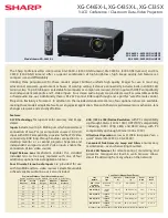
Reviews: