Sharp MZ-80SFD, Service Manual
The Sharp MZ-80SFD Instruction Manual is a comprehensive guide for users seeking to optimize their experience with this exceptional product. Easily download the user manual for free from our website and unlock the full potential of the Sharp MZ-80SFD. Navigate effortlessly through its features and functionalities with this essential manual.
Share
Download


Reviews:
No comments
Related manuals for MZ-80SFD

Que!
Brand: QPS Pages: 41
AMIGA 2010
Brand: Commodore Pages: 20
DataTrak 8
Brand: Qume Pages: 19
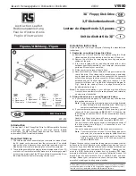
V9580
Brand: RS Pages: 4
RF-4755732
Brand: Renkforce Pages: 4
QumeTrak 242
Brand: Qume Pages: 90
FLOPPY DISK DRIVE
Brand: Freecom Pages: 2
IO-FMP220
Brand: Koutech Pages: 13
TF-20
Brand: Epson Pages: 79
Zip-100
Brand: Epson Pages: 23
Modular Floppy Disk Drive
Brand: Fujitsu Pages: 8
MP-1802
Brand: Hitachi Pages: 92
FB-100
Brand: Brother Pages: 4
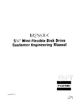
M255XK
Brand: Fujitsu Pages: 94
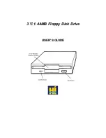
1.44MB Floppy
Brand: HI-VAL Pages: 6
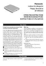
CF-VFD Series
Brand: Panasonic Pages: 8
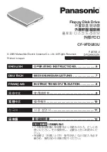
CF-VFDU03U - 1.44 MB Floppy Disk Drive
Brand: Panasonic Pages: 16

CF-VFDU03W
Brand: Panasonic Pages: 8


