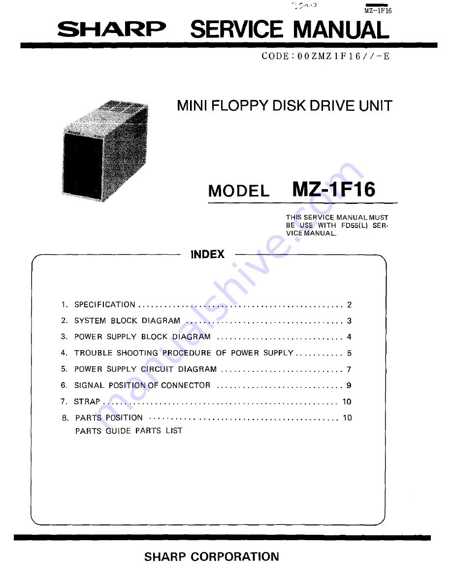
background image

Summary of Contents for MZ-1F16

Page 1: ...ANUAL MUST BE USE WITH FD55 L SE R VICE MANUAL 1 SPECIFICATION _ _ 2 2 SYSTEM BLOCK DIAGRAM 3 3 POWER SUPPLY BLOCK DIAGRAM 4 4 TROUBLE SHOOTING PROCEDURE OF POWER SUPPLY 5 5 POWER SUPPLY CIRCUIT DIAGRAM 7 6 SIGNAL POSITION OF CONNECTOR 9 7 STRAP 10 8 PARTS POSITION _ 10 PARTS GUIDE PARTS LIST SHARP CORPORATION ...

Page 2: ... Voltage 50 60Hz Power consumption 50W Operating temperature 10 C to 35 C Operating humidity 20 to 80 RH w o moisture condensation Physical dimensions 118 W x 331 D x 189 H mm Weight 6 0 kg Accessories Instruction book drive number label power cord Connection procedure 1 In the first place make sure that all powers are off to MZ 5600 and peripheral units 2 Interface the MZ 1 F16 with the MZ 5600 u...

Page 3: ...EP L 17 WROATA r 9 L 23 NR PRO 25 RD DATA 26 SIDE ONE DUST 1357ACZZ 24 READY r 1 14Pin I le SOCKET 9 9995 9 l TERMINATOR 330n x 7 r DRIVE lOJ OAr P s 8 SHQRTPINlOS11 Y 2 B I pj WITHOUT TERMINATOR I v I 1 AI I 0 Y d B IMZ 1 F16 drive CO r c 5V DUNT 1357ACZZ 120n GND GNO 5V 2 igPG2 IGreenl 4 POWER SUPPLY UNIT I 4 IN PUT N en 1CD 3 ID 0 o C III 3 I C O ...

Page 4: ...er switching circuit it starts to oscillate so as to convert the DC voltage into a high frequency AC 20KHz or more power which is rectified through the high frequency ferrite transformer H to produce 5V and 12V supplies Both outputs are stabilized by means of the controller As each of outputs is supplied to the controller control signal is fed back to the primairy side by the means of the saturabl...

Page 5: ...destruction in probes between the emit these components ter and collector of Q1 01 RC1 C4 Cl C16 Should 01 be found in failure there will be need of replacing Gradually increase the the following components as they AC voltage using Slidac may possibly be in destruction too 02 03 Dl D3 Rl1 RS Replace the defective component with the new Put the load into connection in NOTE Should 01 be found in fai...

Page 6: ... range Time range 50V div 10us div TheWaVefQ r mb elow willappear in this case lAC JOOV i J iI W r v 20 3 Fig3 Qutpotvoltage will bel to 1 5V 5 1 output When the AC voltage is increased by means of the Slidac the wave orm appears at the beginning but it disappears _ aMd becomes DC 1 1 yoltage when the AC voltage is further lncreased i I r J W i g CO Qf1 ot may be in failure 04 05 D6 Qa 08 and Q5 m...

Page 7: ...5 Power supply circuit DIAGRAM 5 1 Power supply circuit for 100V series w w filGBS24 AS 7 n l0J0f f AI3S B0875 A MZ 1Fl6 eo m I2Y c w n a Do a a sw 2 DND ...

Page 8: ...5 2 Power supply circuit for 200V series w onr I T 8 ...

Page 9: ...DIRECTION 14 0 13 STEP 16 15 WR DATA 18 17 G N WR GATE 20 19 D TRACK 0 22 21 WR PRO 24 REDY 23 RD DATA 26 SIDE 25 27 29 31 33 J330n J rn IDipSWI ITolF161 MFD ITo FD 55FILII No Signal Name 2 4 HEAD LOAD 6 8 INDEX 10 SEL 0 12 SEL 1 14 16 MOTOR ON 18 DIRECTION 20 STEP 22 WR DATA 24 WR GATE 26 TRACKO 28 WRPRO 30 RD DATA 32 SIDE 34 REDY Dip SW Position Dip SW Select IMZ1F161 1 ON SELC 2 ON SELD NOTE ON...

Page 10: ...0 0 0 0 0 D nO 0 0 0 0 0 0 IF 0 0 0 0 0 0 0 0 8 Parts position J Drive C SIDE i i VR 1 0 0 ML NO TERMINAT 1 0 0 IU RES ISTbR I 111 1 HL SM M _I PM 0 0 VD i i J 0 0 VI 0 0 RE Drive 0 SIDE VR ML NO TERMINATOR IU i RESISTOR HI I W l SM PM 0 0 VD 0 0 VI 0 0 RE D SIDE C SIDE 10 ...

Page 11: ...J10B3CCZZ AA 26 PHOG 1023CCZZ AB 27 QPLGAOO18WREl AN 28 DUNT 1127ACZZ BX DUNT 1100ACZZ BU 21 13 9 12 20 PART DESCRIPTION RANK E I F PWB unit E LED PWB unit D Lid for connector D AnRle for PWB D Mini clump S 5 S 5 C S acer for PWB C AC cord Europe Others 22DV C AC cord UK So Afri _ C AC cord For Australia j6A 250Vi E Mini flo y disk drive D Frontm nel D Cabinet D Chassis D SHARP Badge C Rubber foot...

Page 12: ...AC 0 AA 0 AA D AA 0 D E S C Ri 1 T ION i 1 Connector pin Connector 2 in Connector cable I re socket 14cjn DiD SW Resistor 1 4W 1200 5 CED Gl9PG2 LED cable _ L C DESCRJPTIQN Media Caution Drive No la bel ABCD Drive No label EFGH DD label Instruction book Packinll cushion Packing case Cord sleeve Vinyl bai 500X500mm Vinyl baR 14QX26Dmm Vinyl ba 100X 300mni Vinyl bag 50X60mm Electronic parts for 200V...

Page 13: ... Coil EBl 3 00 Coil 8EBl 3 0D Iadiaor adiator oil 5J Exteriors for 200V series power supply P 1 S 0 4 50 XIPS 007 O E 5 889 ID 20 11 A cl 2 12 A cl D le 2 11 A 2 49 14 AE 35 5 5 15 N E 4 0 0 0 15 A E 0 3 6 4 17 A E 0 4 0 5 A AA Y V A A A A G crew crew hasS s I ove 21 orew ire harness switch Inlet Terminal Bushing lushlng ut use use holder J Electronic p rts for lOOV series power supply iJA 2582 R ...

Page 14: ...istor S Vl V F lVl 22 W 12 Kn 2WJ 51 0 W 5W W W I Resistor OJ SW ReS lJ 2SW R arial res tor 40 B 63 00 I i 3_ 0 i Ooarts dia LZJ Exteriors for lOOV series UVVtH supplv NO 1 2 x 11 PARTS CODE P 4 4 P 6 6 2 S 00 PRICE NEW PART RANK MARK RANK I A lA ut crew lire harness _itch ID irlet Jus ing Jus ing 4 DE SCRIPTION DESCRIPTION R2S CR ...

Page 15: ...MZlF16 5J rn Exteriors for power supply 5 131 _ 6 9 14 4 5 ...

Page 16: ...SHARP SHARP CORPORATION Industrial Instruments Group Reliability Quality Control Department Yamatokoriyama Nara 639 11 Japan 1984 June Printed in Japan ...

Reviews: