MD-MT88H/99H
Page
SAFETY PRECAUTION FOR SERVICE MANUAL ............................................................................................................... 2
SPECIFICATIONS ................................................................................................................................................................. 3
ACCESSORIES ..................................................................................................................................................................... 5
NAMES OF PARTS ............................................................................................................................................................... 6
OPERATION MANUAL .......................................................................................................................................................... 7
DISASSEMBLY .................................................................................................................................................................... 12
REMOVING AND REINSTALLING THE MAIN PARTS ....................................................................................................... 13
ADJUSTMENT ...................................................................................................................................................................... 14
MD ERROR MESSAGE DISPLAY CONTENT LIST ........................................................................................................... 27
NOTES ON SCHEMATIC DIAGRAM .................................................................................................................................. 28
TYPES OF TRANSISTOR AND DIODE .............................................................................................................................. 28
BLOCK DIAGRAM ............................................................................................................................................................... 29
SCHEMATIC DIAGRAM ...................................................................................................................................................... 30
WIRING SIDE OF P.W.BOARD ........................................................................................................................................... 32
VOLTAGE ............................................................................................................................................................................ 35
WAVEFORMS OF MD CIRCUIT ......................................................................................................................................... 36
TROUBLESHOOTING ......................................................................................................................................................... 37
FUNCTION TABLE OF IC .................................................................................................................................................... 40
PARTS GUIDE/EXPLODED VIEW
PACKING METHOD (FOR U.K. ONLY)
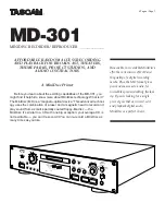
MD-MT88H(S)
MODEL
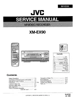
MD-MT99H(S)/(BL)
CONTENTS
SERVICE MANUAL
SHARP CORPORATION
No. S6138MDMT88HS
This document has been published to be used
for after sales service only.
The contents are subject to change without notice.
• In the interests of user-safety the set should be restored to its
original condition and only parts identical to those specified be
used.
PORTABLE MINIDISC RECORDER
Illustration: MD-MT88H
Illustration: MD-MT99H