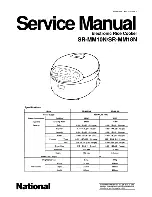
SHARP CORPORATION
SHARP SERVICE MANUAL
TABLE OF CONTENTS
IMPORTANT SAFEGUARDS .......................................................................................................
PRECAUTIONS ............................................................................................................................
NAME OF PARTS ........................................................................................................................
SPECIFICATION ..........................................................................................................................
PART SPECIFICATION ................................................................................................................
CAUTIONS ...................................................................................................................................
CIRCUIT DIAGRAM .....................................................................................................................
EXPLANATION OF CIRCUIT ................................................................................................
HOW TO ADJUST THE CLOCK ...........................................................................................
REPLACING METHOD FOR MAIN PARTS ...........................................................................
CAUTIONS IN ASSEMBLY ..................................................................................................
COOKING/WARMING TEST METHOD .................................................................................
INSPECTION AND OPERATION CHECK ..............................................................................
BEFORE CALLING FOR SERVICE ......................................................................................
SERVICING .......................................................................................................................
POST-REPAIR INSPECTION ...............................................................................................
TROUBLESHOOTING GUIDE ..............................................................................................
SERVICE PARTS LIST ........................................................................................................
Page
2
2
3
4
5
6-7
8-10
11
11
12-16
16
17-18
19-20
21
22
22
23-25
26-30
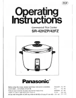
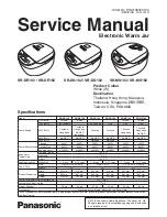
ELECTRONIC JAR RICE
COOKER/WARMER
MODELS
KS-M102
KS-M182
In the interests of user-safety (Required by safety
regulations in some countries) the set should be restore to
its original condition and only parts identical to those
specified should be used.
Summary of Contents for KS-M102
Page 8: ...8 CIRCUIT DIAGRAM ...
Page 9: ...9 SCHEMATIC DIAGRAM PCB ass y ...
Page 10: ...10 ...
Page 30: ...30 ...