1
KSH-777DW
SY307KSH777DW
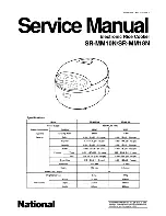
SERVICE MANUAL
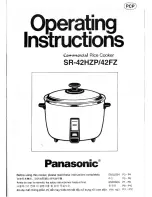
COMMERCIAL
RICE COOKER
MODEL
In the interests of user-safety (Required by safety regulations in some
countries) the
uni
t should be restored to its original condition and only
parts identical to those specified should be used.
KSH-777DW
SHARP CORPORATION
This document has been published to be used for after
sales service only.
The contents are subject to change without notice.
Page
IMPORTANT SAFEGUARDS ............................................................................................................................ 2
PRECAUTIONS ................................................................................................................................................. 2
SPECIFICATIONS ............................................................................................................................................. 3
PART NAMES .................................................................................................................................................... 3
HOW TO USE .................................................................................................................................................... 3
COOKING CHART ............................................................................................................................................. 4
CLEANING AND CARE ..................................................................................................................................... 4
SCHEMATIC DIAGRAM .................................................................................................................................... 5
TROUBLE SHOOTING ..................................................................................................................................... 6
COMPONENT REPLACEMENT PROCEDURE ................................................................................................ 7
SIMPLIFIED TESTING METHOD ...................................................................................................................... 9
INSPECTION AFTER REPAIRING ................................................................................................................. 10
REPLACEMENT PARTS LIST ........................................................................................................................ 11
TABLE OF CONTENTS
COOK