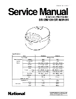
SHARP CORPORATION
SHARP SERVICE MANUAL
TABLE OF CONTENTS
PARTS IDENTIFICATION AND SPECIFIC INFORMATION ......................................................
CAUTIONS FOR USE ...............................................................................................................
CLEANING AND CARE .............................................................................................................
WIRING DIAGRAM AND CIRCUIT DIAGRAM ..........................................................................
COMPONENT REPLACEMENT PROCEDURE .......................................................................
INSPECTION AFTER ASSEMBLING .......................................................................................
SIMPLIFIED TESTING METHOD .............................................................................................
PRECAUTIONS FOR WARM-KEEPING TO GET TASTY RICE ..............................................
TROUBLESHOOTING ..............................................................................................................
Page
2
3
4
5
6 - 11
12 - 13
14 - 15
16
17 - 18
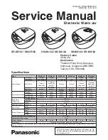
JAR RICE COOKER
MODELS
KS-18EV / ETV
KS-181EV / ETV
KS-182ETV
In the interests of user-safety (Required by safety
regulations in some countries) the set should be restore
to its original condition and only parts identical to those
specifi ed should be used.