1
KB-6015KS
KB-6015KK
KB-6015KW
In the interest of user-safety the unit should be restored to its original condition and only parts identical to those specified
should be used.
WARNING TO SERVICE PERSONNEL:
This service manual is intended for use by persons having electrical and mechanical training and a level of
knowledge of these subjects generally considered acceptable in the appliance repair trade. Sharp Electronics
Corporation cannot be responsible, nor assume any liability, for injury or damage of any kind arising from the
use of this manual.
Microwave ovens contain circuitry capable of producing very high voltage and current. Contact with the
following parts may result in a severe, possibly fatal, electrical shock. (High Voltage Capacitor, High Voltage
Power Transformer, High Voltage Rectifier and Heat sink etc., and Magnetron, High Voltage Harness etc..)
S25M246KB6015
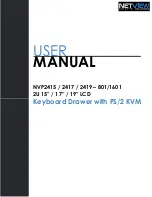
KB-6015KS
KB-6015KK
KB-6015KW
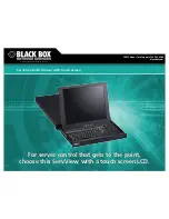
MICROWAVE DRAWER
MODELS
SERVICE MANUAL
TABLE OF CONTENTS
Page
PRECAUTIONS TO BE OBSERVED BEFORE AND DURING SERVICING TO
AVOID POSSIBLE EXPOSURE TO EXCESSIVE MICROWAVE ENERGY ................... INSIDE FRONT COVER
BEFORE SERVICING ...................................................................................................... INSIDE FRONT COVER
WARNING TO SERVICE PERSONNEL ............................................................................................................... 1
MICROWAVE MEASUREMENT PROCEDURE ..................................................................................................... 2
FOREWORD AND WARNING ................................................................................................................................ 3
PRODUCT SPECIFICATIONS ............................................................................................................................... 4
SCHEMATICS ....................................................................................................................................................... 8
TEST PROCEDURES ............................................................................................................................................ 9
TOUCH CONTROL PANEL ASSEMBLY ............................................................................................................. 17
MICROWAVE DRAWER DISASSEMBLY ............................................................................................................ 25
WIRING DIAGRAMS ........................................................................................................................................... 31
PRINTED WIRING BOARDS ............................................................................................................................... 32
PARTS LIST ........................................................................................................................................................ 36
PACKING AND ACCESSORIES ......................................................................................................................... 40
This document has been published to be used for after sales service only. The contents are subject to change without notice.
SHARP ELECTRONICS CORPORATION
KB-6015KS pictured