background image


S9381 

In the interests of user-safety the set should be restored to its original

condition and only parts identical to those specified be used.


Page

.. .............................................................................................................

2

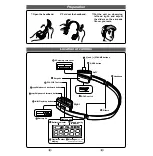
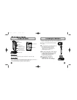
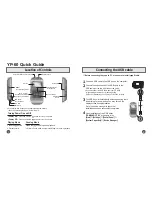
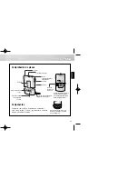
NAMES OF PARTS ........................... ....................................................................................

2

DISASSEMBLY.. .................. ..................................................................................................

3

REMOVING AND REINSTALLING THE MAIN PARTS.. ....................................................... 4

ADJUSTMENT .......................................................................................................................

5

NOTES ON SCHEMATIC DIAGRAM ....................................................................................

6

TYPES OF TRANSISTOR AND LED ...................... ............................................................... 6

OF DIAL POINTER ............................... . . ................................................................... 6

EXPLODED VIEW ......................................... ....................................................................


SCHEMATIC DIAGRAM 

SIDE OF

............................................. 9-12

REPLACEMENT PARTS LIST .......................................................................................

13-15


Summary of Contents for JG545X

Page 1: ...ical to those specified be used INDEX TO CONTENTS Page SPECIFICATIONS 2 NAMES OF PARTS 2 DISASSEMBLY 3 REMOVING AND REINSTALLING THE MAIN PARTS 4 ADJUSTMENT 5 NOTES ON SCHEMATIC DIAGRAM 6 TYPES OF TRANSISTOR AND LED 6 FITING OF DIAL POINTER 6 EXPLODED VIEW 7 a SCHEMATIC DIAGRAM WIRING SIDE OF P W BOARD 9 12 REPLACEMENT PARTS LIST 13 15 SHARP CORPORATION ...

Page 2: ...e 40 15 000 Hz MetaKrOJNormal tape Radio Frequency range F M aa 108 M H Z AM 526 5 1 606 5 kHz Headphones Type Impedance Inner ear dynamic 24 ohms Specifications for this model are subject to change without prior notice NAMES OF PARTS 1 Power Battery Indicator 2 Extra Bass Switch X BASS 3 Volume Control 4 FunctionTape Selector switch 5 Headphones Socket 6 Tape Direction Switch 41 7 Stop Button q 8...

Page 3: ...e unit 3 After servicing the unit be sure to rearrange the leads where they were before disassembling 4 Take sufficient care on static electricity of integrated circuits and other circuits when servicing Front Cabinet Cassette Compartment I Front Cabinet k Rear Cabinet 1 y Front Cabinet Button Cover B on Cover Black Figure 3 l Figure 3 2 Figure 3 3 Dl x 1 Front Cabinet u y M o t o r Figure 3 4 Fl ...

Page 4: ...tor belt See Fig 4 2 1 Remove the motor belt Cl xl pc 2 Remove the main belt C2 x 1 pc How to remove the motor See Fig 4 2 I Remove the motor belt Cl x 1 pc 2 Remove the screws Dl x 2 PCS to remove the motor How to remove the flywheel See Figs 4 2 and 4 3 1 Remove the main belt C2 x 1 pc 2 Remove the washers Dl x 2pcs 3 Remove the stop washers D2 x 2 PCS with a small precision screwdriver to extra...

Page 5: ...nes Socket T F Tl 455 kHz Obtain the best output Input Antenna Output TP3 Maximize the output Input Antenna Output Headphones Socket Lord resistance 24 ohms l Tape Speed Test Tape Adjusting Specified value Instrument Connection Point MTT 111 VR201 3 000 90 Hz Headphones Socket 3and overage fL L3 510 kHz fH TC3 1 650 kHz Tracking fL L4 600 kHz fH Checking I 400 kHz Maximize the output input Antenna...

Page 6: ...ene type DTC144 EK 2SC1623 L6 2SKl067 TR Cl B2 E2 E l Bl C2 IMD6 l The indicated voltage in each section is the one measured by Digital Multimeter between such a section and the chassis with no signal given 1 Tuner FM mode FM stereo mode Mraking except for c 5 AM mode l Schematic Diagram and Wiring Side of P W Board forthis model are subject to change for improvement without prior notice REF NO 1 ...

Page 7: ...I 0 AM S I G N A L s a p L A _ L301 r CONVERTER I26 OOP I CH C d PLAYBACK HEAD L w DPHONES Q102 2 DICI 44EK YZII I a 2 c I cf K 4 i Z 4 7 P v l NOTES ON _ _ _ SCHEMATIC UIAtiHAM can be tout d on page 6 1 2 3 4 5 6 1 Figure 9 SCHEMA ...

Page 8: ... S 3 A A s IZE f UWSUM 3 R E or HP7lX2 Y2F or E X T E R N A L D C 3 X B A S S 1 Q103 T 25C1623 16 MUTING 7cE 3 3K X B A S S SW 02 B 4 O N OFF ICZOI MM1 038BF MOTOR YI D R I V E R 1 Y 2 CZOl bB l 4 C203 0 0 2 2 II II c20 2 220 A X B A S S PI04 ZSCI 6 2 3 L6 12 I HEMATIC DIAGRAM lO ...

Page 9: ...I I I I I I I 7 I 1 1GY f UNER PWB A 1L4 A M BAR ANT BATTERY TERMlNf 128 BATTERIE S AA S I Z E iUM SUM 3 or e x t e r n a l D C 3v i 7 B T IR I I Figure 11 WIRING SIDE ...

Page 10: ... M A L M E T A L VOLUME r y CrO2 I r1 8 T BATTERIES DC 3V Uhl SUM 3 R6 a l D C 3V or HP 71 x 2 11201 BATTERY TERMINAL R 1 SPEED 1 GR WI01 CTION SW 104 MAIN PLAY BACK H E A D ASS Y II1 yL rL J102 EXT DC POWER MI MOTOR 7 8 9 10 11 12 I llNG SIDE OF P W BOARD 12 ...

Page 11: ... F A G A D THERMISTOR PR202 RH QXOlOZPFZZ J Posistor l ohm A C CAPACITORS There are two types of capacitors available and they can be identified from each other by reading their Part Numbers Ceramic type capacitor A symbol C or K is given at the 3rd digit of its Part Number like VCC or K J Semiconductor type capacitor A symbol T is given at the 3rd digit of its Part Number like VCT J The capacitan...

Page 12: ... A R15 VRS TV2AB272J J 2 7 kohms l lOW A A R16 VRS TV2AB331J J 330 ohms l lOW A A R17 VRS TV2AB474J J 470 kohms l lOW A A R18 19 VRS TVZAB104J J 100 kohm l lOW A A R20 VRS TV2AB563J J 56 kohms l lOW A A 14 REF NO R101 102 R103 104 R107 108 R109 llO R111 112 R113 114 R115 116 R117 118 R119 120 R121 122 R123 R124 R125 R126 RI27 R129 130 R131 132 R133 R201 R202 203 R204 R205 R301 R302 JlOl J102 Ml Pl...

Page 13: ...Type MAIN CABINET PARTS A H A D A D A A A W A G SW104 A F 101 102 103 104 105 106 107 108 109 110 111 112 113 114 115 117 118 119 120 121 122 123 124 125 126 128 129 GCABA0139PFSA J Front Cabinet GCABB0150PFSA J Rear Cabinet GFTABOlOlPFSA J LidBattery GCoVA0225PFSA J Button Cover GFTACO 152PFSA J Cassette Compartment GMADi0103PFSA J Window Dial GMADiOlD4PFSA J Window Cassette HBDGBO 105PFSA J Badg...

Page 14: ...SHARF A9309 853YM TA P Writer and Editor Quality Reliability Control Center of Communication Audio Systems Group Sharp Corp Printed in Japan EX ...

Reviews: