background image

FO-71TH/UX-61TH/GQ-56TH/FO-51TH

UX-41TH/GQ-31TH/UX-21TH/FO-11TH/GQ-11TH

No. 00ZFO71TH/SME

CHAPTER 1. GENERAL DESCRIPTION
[1] Specifications ............................................ 1-1
[2] Operation panel ......................................... 1-2
[3] Transmittable documents .......................... 1-3
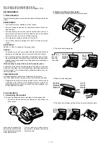
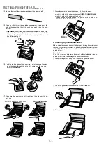
[4] Installation ................................................. 1-4
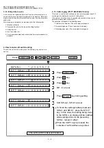
[5] Quick reference guide ............................... 1-8

CHAPTER 2. ADJUSTMENTS
[1] Adjustments ............................................... 2-1
[2] Diagnostics and service soft switch .......... 2-2
[3] Troubleshooting......................................  2-18
[4] Error code table ....................................... 2-19

CHAPTER 3. MECHANISM BLOCKS
[1] General description ..................................  3-1
[2] Disassembly and assembly
              procedures ....................................... 3-3

CHAPTER 4. DIAGRAMS
[1] Block diagram ............................................4-1
[2] Wiring diagram .......................................... 4-2
[3] Point-to-point diagram ............................... 4-3

CHAPTER 5. CIRCUIT DESCRIPTION
[1] Circuit description ...................................... 5-1
[2] Circuit description of control PWB .............. 5-2
[3] Circuit description of TEL/LIU PWB .......... 5-9
[4] Circuit description of
            power supply PWB ............................ 5-12
[5] Circuit description of CIS unit ................... 5-12

CHAPTER 6. CIRCUIT SCHEMATICS AND
PARTS LAYOUT
[1] Control PWB circuit ................................... 6-1
[2] TEL/LIU PWB circuit ................................. 6-9
[3] Power supply PWB circuit ......................  6-14
[4] Operation panel PWB circuit ................... 6-16

CHAPTER 7. OPERATION FLOWCHART
[1] Protocol ..................................................... 7-1
[2] Power on sequence .................................. 7-2

CHAPTER 8. OTHERS
[1] Service tools .............................................. 8-1
[2] Rewriting version up the FLASH ROM ....... 8-4
PARTS GUIDE

CONTENTS

FACSIMILE

Parts marked with "

" is important for maintaining the safety of the set. Be sure to replace these parts with specified ones for

maintaining the safety and performance of the set.

This document has been published to be used
for after sales service only.
The contents are subject to change without notice.

SHARP CORPORATION

SERVICE MANUAL

Illustration: FO-71TH

FO-71/51/11

UX-61/41/21

GQ-56/31/11

MODEL

SELECTION CODE

DESTINATION

TH

Thailand

Cutter model

Non cutter model

FO-71/UX-61/GQ-56

FO-51/11 UX-41/21 GQ-31/11

Memory model

Non memory model

FO-71/51 UX-61/41 GQ-56/31

UX-21/FO-11/GQ-11

Summary of Contents for FO-71

Page 1: ...scription of CIS unit 5 12 CHAPTER 6 CIRCUIT SCHEMATICS AND PARTS LAYOUT 1 Control PWB circuit 6 1 2 TEL LIU PWB circuit 6 9 3 Power supply PWB circuit 6 14 4 Operation panel PWB circuit 6 16 CHAPTER 7 OPERATION FLOWCHART 1 Protocol 7 1 2 Power on sequence 7 2 CHAPTER 8 OTHERS 1 Service tools 8 1 2 Rewriting version up the FLASH ROM 8 4 PARTS GUIDE CONTENTS FACSIMILE Parts marked with is important...

Page 2: ...ä käytetty paristo valmistajan ohjeiden mukaisesti French ATTENTION Il y a danger d explosion s il y a remplacement incorrect de la batterie Remplacer uniquement avec une batterie du même type ou d un type recommandé par le constructeur Mettre au rébut les batteries usagées conformément aux instructions du fabricant Swedish VARNING Explosionsfare vid felaktigt batteribyte Använd samma batterityp e...

Page 3: ...ne network Compatibility ITU T CCITT G3 mode Input document size Automatic feeding Width 148 to 210 mm Length 140 to 297 mm Manual feeding Width 148 to 210 mm Length 140 to 600 mm Effective scanning width 210 mm max Effective printing width 210 mm max Contrast control Automatic Dark selectable Reception modes TEL FAX TEL FAX A M Note A M mode is for connecting an answering machine Copy function Ye...

Page 4: ...me press this key to print out the Help List a quick reference guide to the opeation of your fax machine 11 RESOLUTION RECEPTION MODE key When a document is in the feeder press this key to adjust the resolution for faxing or copying At any other time press this key to select the reception mode an arrow in the display will point to the currently selected reception mode 12 SPEAKER key Press this key...

Page 5: ...ument carrier sheet for smaller documents Readable width Min Max A4 size Max 140mm 297mm 600mm 148mm 210mm Normal size 210mm Special size 3 Document Types Normal paper Documents handwritten in pencil No 2 lead or softer fountain pen ball point pen or felt tipped pen can be transmitted Documents of normal contrast duplicated by a copying machine can also be transmitted Diazo copy blue print Diazo c...

Page 6: ...he power and telephone lines Surge protectors can be purchased at most telephone specialty stores If the machine is moved from a cold to a warm place Condensation may from on the reading glass if machine is moved from a cold to a warm place this will prevent proper scanning of documents for transmission Turn on the power and wait approximately 2 hours be fore using machine TELEPHONE JACK A standar...

Page 7: ...elect the dial mode TONE PULSE 4 Press to exit 1 2 OPTION SETTING Display DIAL MODE FUNCTION 4 STOP 5 Moving your fax and reconnecting If it is necessary to move your fax to a new location first disconnect the telephone line cord before disconnecting the power cord When reconnecting it is necessary to connect the power cord before con necting the telephone line cord 6 Attaching the original docume...

Page 8: ... is placed backwards the paper will come out blank after printing 4Unwrap the roll of thermal paper and insert the paper shaft 6Insert the leading edge of the paper into the slot as shown Continue to push the paper through the slot until it comes out the opening in the front of the machine 7Make sure the paper comes out straight and then flip down the pa per guide 4 Clearing a jammed document If t...

Page 9: ...t pieces of paper from the paper compartment FO 71 UX 61 GQ 56 Only FO 51 11 UX 41 21 GQ 31 11 FO 71 UX 61 GQ 56 Press the knob to mark sure the front side of the metal guide is down 5 Clearing jammed printing paper 1Grasp the finger hold and pull up to open the operation panel 2Flip up the front paper guide 4Cut off the wrinkled part of the paper 5Reload the paper Jammed paper is often caused by ...

Page 10: ... START FAX TEL FAX TEL 05 NOV 10 30 A M TEL FAX A M TEL FAX 05 NOV 10 30 FAX TEL FAX TEL 05 NOV 10 30 A M TEL FAX A M TEL FAX 05 NOV 10 30 RESOLUTION RECEPTION MODE TEL mode Answer all calls even faxes by picking up the handset To begin fax reception press FAX mode The fax machine automatically answers and receives faxes TEL FAX mode The fax machine automatically answers and receives faxes Voice c...

Page 11: ...istering again the mode which was registered formerly is shown STOP 1 TONE 2 PULSE 2 IC protectors replacement ICPs IC Protectors are installed to protect the motor driver circuit ICPs protect various ICs and electronic circuits from an overcurrent con dition The location of ICPs are shown below CNLIUA CNPW CONTROL PWB TOP SIDE CNMT FU100 1 FU100 KAB3202 is installed in order to protect IC s from ...

Page 12: ... C Signal send mode START START KEY STOP KEY Power ON Memory clear Work Backup TA50 TA43 All black mode START START Auto feeder mode START Entry data send START E Entry data receive Cutter aging FO 71 UX 61 GQ 56 only START D Shading mode START START Memory clear TA37 COUNTRY NAME 2 2 2 Diagnostic items ITEM No DIRECT Key Contents 1 SOFT SWITCH MODE Soft switches are displayed and changed List can...

Page 13: ...mode This mode is used to send various signals to the circuit during FAX com munication Every push of START key sends a signal in the following sequence Moreover the signal sound is also output to the speaker when the line monitor of the soft switch is on 1 No signal CML signal turned on 2 9600bps 3 7200bps 4 4800bps 5 2400bps 6 300bps FLAG 7 2100Hz CED 8 1100Hz CNG 9 Pseudo Ring models with auto ...

Page 14: ...sent from the other machine is re ceived and the received data is registered in the machine When this mode is used for receiving the other machine must be in the entry data send mode After receiving is completed the machine prints the following lists 1 Telephone list data 2 Passcode No only for the type with polling function 3 Soft switch list 4 Junk fax number list 5 Timer reservation data only m...

Page 15: ... CNG transmission No Yes 0 CED tone signal interval 1000ms 750ms 500ms 75ms 1 No 1 1 1 0 0 0 2 No 2 1 0 1 0 0 3 MR coding No Yes 0 4 Reserved 0 5 Reserved 0 6 Reserved 0 7 Reserved 0 8 Reserved 0 Signal transmission level Binary input 0 31 dBm setting by 1 dBm step No 16 8 4 2 1 1 1 2 3 4 5 0 2 0 0 1 0 0 4dB 0 3 1 4 0 5 0 6 Protocol monitor error print Printed at com error Not printed 0 7 Protocol...

Page 16: ...in step No 16 8 4 2 1 1 6 4 5 6 7 8 0 7 0 1 0 1 0 1 8 0 1 Recall times 0 15 times setting Binary input 0 2 No 8 4 2 1 0 3 1 2 3 4 1 4 0 0 1 0 0 5 Dial tone detection before auto dial No Yes 1 6 Reserved 0 7 Busy tone detection after auto dial No Yes 1 8 Busy tone detection pulse number after auto dial 4 pulses 2 pulses 0 Waiting time after dialing 45 seconds 55 seconds 90 seconds 140 seconds 1 No ...

Page 17: ...vel Binary input High frequency 0 15 5 dBm setting by 0 5 dBm step No 16 8 4 2 1 1 2 3 4 5 1 0 1 0 0 1 0 2 1 3 0 4 0 5 1 6 Reserved 0 7 Reserved 0 8 Reserved 0 Reading slice Binary Factory Light Dark Darker in setting dark 1 No 1 0 1 0 1 0 2 No 2 0 0 1 1 0 Reading slice Half tone Factory Light Dark Darker in setting dark 3 No 3 0 1 0 1 0 4 No 4 0 0 1 1 0 5 Line density selection Fine Standard 0 6 ...

Page 18: ... 3 0 1 0 1 0 1 0 1 0 4 Number of CNG signal detection at the Twice Once 1 TEL FAX automatic switching mode 5 CNG detection period when TEL FAX mode 3 sec 5 sec 0 6 Post answer tone TEL FAX mode No Yes 1 7 Type of post answer tone LA SI DO tone 800Hz single tone 1 8 Pseudo ringer ON OFF cycle 1 sec ON 4 sec OFF 1 sec ON 2 sec OFF 0 1 Pseudo ringer sound modem TX level Binary input 1 2 0 15 dBm sett...

Page 19: ...0 8 Reserved 0 1 Quiet detect time Binary input 0 OPTION 2 0 15 sec setting by 1 sec step No 8 4 2 1 1 3 1 2 3 4 0 4 0 1 0 0 0 5 Quiet detect start timing Binary input 0 OPTION 6 0 15 sec setting by 1 sec step No 8 4 2 1 1 7 5 6 7 8 0 8 0 1 0 1 1 1 Reserved 0 2 Reserved 0 3 Reserved 0 4 Reserved 0 5 Reserved 0 6 Reserved 0 7 Reserved 0 8 Reserved 0 OGM detect timer Not work 100ms 200ms 300ms 1 No ...

Page 20: ...1 0 1 0 Busy tone detection ON OFF time Upper 650ms 900ms 1500ms 2700ms 3 duration No 3 0 0 1 1 0 4 No 4 0 1 0 1 1 5 Reserved 0 6 Reserved 0 7 Reserved 0 8 Reserved 0 1 Reserved 0 2 Reserved 0 3 Reserved 0 4 Reserved 0 5 Reserved 0 6 Reserved 0 7 Reserved 0 8 Reserved 0 1 Reserved 0 2 Reserved 0 3 Reserved 0 4 Reserved 0 5 Reserved 0 6 Reserved 0 7 Reserved 0 8 Reserved 0 1 Reserved 0 2 Reserved 0...

Page 21: ...served 0 8 Reserved 0 1 Reserved 0 2 Reserved 0 3 Reserved 0 4 Reserved 0 5 Reserved 0 6 Reserved 0 7 Reserved 0 8 Reserved 0 1 Sender s phone number setting Cannot change Change allowed 0 2 Reserved 0 Ringer volume Off Low Middle High OPTION 3 No 3 0 0 1 1 1 4 No 4 0 1 0 1 0 Speaker volume Low Low Middle High OPTION 5 No 5 0 0 1 1 1 6 No 6 0 1 0 1 0 7 Polling key Yes No 0 OPTION 8 Reserved 0 1 Re...

Page 22: ...tion report No 1 0 0 0 0 0 2 No 2 0 0 1 1 0 3 No 3 0 1 0 1 0 4 Time format 12 hour 24 hour 0 5 Date format Month Day Year Day Month Year 0 6 Reserved 0 7 Reserved 0 8 Reserved 0 1 Entering diag mode by pressing SPEED key Yes No 0 2 Reserved 0 3 Reserved 0 4 Reserved 0 5 Reserved 0 6 Reserved 0 7 Reserved 0 8 Reserved 0 SW NO DATA NO ITEM SW l J3 SW l K1 1 0 Remarks Initial setting TH ...

Page 23: ... SW A2 No 5 Reserved Set to 0 SW A2 No 6 H2 mode Used to determine reception of H2 mode 15 sec transmission mode When set to OFF H2 mode reception is inhibited even though the trans mitting machine has H2 mode function SW A2 No 7 Communication error treatment in RTN sending mode Reception Used to determine communication error treatment when RTN is sent by occurrence of a received image error in G3...

Page 24: ... timer Used to make a choice of whether to use the 5 or 13 or 20 or 25 seconds timer for detection of EOL This is effective to override communication failures with some facsimile models that have longer EOL detection SW A7 No 3 No 8 Reserved Set to 0 SW B1 No 1 Hold key Used to set YES NO of holding function by the HOLD key SW B1 No 2 Auto dial fax transmission by REDIAL key When set to 1 if origi...

Page 25: ...mode which is automatically selected when the Resolution key is not pressed In the copy mode however the fine mode is automatically selected unless the Resolution key is manually set to another mode SW C1 No 6 Reserved Set to 0 SW C1 No 7 MTF correction in half tone mode This allows selection of MTF correction dimness correction in the half tone mode When NO 1 is selected the whole image becomes s...

Page 26: ... No 1 No 4 Quiet detect time 0 15sec setting by 1sec step When an answering machine is connected if a no sound state is de tected for a certain period of time the machine judges it as a transmis sion from a facsimile machine and automatically switches to the FAX mode SW G1 No 5 No 8 Quiet detect start timing 0 15sec setting by 1sec step Inserts a pause before commencing quiet detection SW G2 No 1 ...

Page 27: ... The upper limit can be set in the range of 650msec to 2700msec SW H2 No 5 No 8 Reserved Set to 0 SW I1 No 1 No 8 Reserved Set to 0 SW I2 No 1 No 8 Reserved Set to 0 SW I3 No 1 No 8 Reserved Set to 0 SW I4 No 1 No 8 Reserved Set to 0 SW I5 No 1 No 8 Reserved Set to 0 SW I6 No 1 No 8 Reserved Set to 0 SW I7 No 1 No 8 Reserved Set to 0 SW I8 No 1 No 8 Reserved Set to 0 SW J1 No 1 Sender s phone numb...

Page 28: ...l exist on the machine use the following format and check the related matters TO ATT Ref No CC ATT Date FM Dept Sign Please complete this report before calling the TAC hotline if problem still occurs Facsimile communication problem Ref No Date From Mr Fax Tel No Our customer Name Tel No Address Fax No Contact person Model name Other party Name Tel No Address Fax No Contact person Model name Proble...

Page 29: ...evealed to be impossible 12 Error occurred just after fallback 13 Error occurred after a response to retransmission end command was received G3 Reception Code Final received signal Error Condition Receiver side 0 Incomplete signal frame Cannot recognize bit stream after flag 1 NSS DCS Cannot recognize CFR or FTT signal Disconnects line during transmission line error 2 NSC DTC Cannot recognize NSS ...

Page 30: ... according to the document thickness Documents corresponding to a paper weight heavier than 69 2kg 80g m2 and lighter than 135kg 157g m2 are acceptable for manual feed Documents heavier than 135kg in terms of the paper weight must be duplicated on a copier to make it operative in the facsimile 3 4 Loading the documents 1 Make sure that the documents are of suitable size and thickness and free from...

Page 31: ...nce and low operating costs 1 Thermal head The thermal head consists of 1728 dot heat elements arranged in a sin gle row and has the resolution of 8 dots mm The maximum recording speed is 10ms line The thermal head also incorporates a 1728 dot shift register latch and output control driver circuit Low power consumption is achieved by dividing the head into nine segments 2 Structure of the recordin...

Page 32: ...rt in a same section are common to each other To assure reliability of the product the disassembly and the assembly procedures should be performed carefully and deliberately Paper support guide handset cover and scanner unit 1 Parts list Fig 1 Fig 1 3 3 Hook Hook Hook Hook Hook Control PWB Hook 2 2 3 4 5 1 7 8 9 6 12 11 10 10 2 3 4 5 1 6 12 11 7 8 9 10 Fix position of spring 4 5 12 12 No Part name...

Page 33: ...Part name Q ty No Part name Q ty 1 Document guide lower 1 2 Back roller gear 1 3 Back roller bearing left 1 4 CIS release lever left 1 5 Back roller 1 6 CIS release lever right 1 7 Back roller bearing right 1 8 Reduction gear 17 28z 1 9 Reduction gear 17 23z 1 3 4 CIS unit and scanner frame 2 2 3 4 5 1 7 8 9 6 12 13 13 14 14 13 14 15 15 16 15 11 16 16 17 18 10 19 Hook Hook Hook Hook 2 3 4 5 1 7 8 ...

Page 34: ... Operation panel unit drive unit hopper guide 3 Parts list Fig 3 8 Drive unit 1 9 Cutter arm 1 FO 71 UX 61 GQ 56 only 10 Screw 3 10 2 11 Hopper guide unit 1 12 Operation panel unit 1 document guide upper unit 13 Screw 1 14 Pinion gear 1 15 Hopper spring 1 16 Hopper guide left 1 17 Hopper guide right 1 18 Hopper guide 1 No Part name Q ty No Part name Q ty 1 Mechanism unit 1 2 Connector 2 3 Operatio...

Page 35: ... Fix position Hook Hook Fig 4 3 6 Upper cabinet and document guide upper 4 Parts list Fig 4 11 Feed plate 1 12 Document guide upper 1 13 Screw 2 6 3 14 Connector 1 15 Operation panel PWB unit 1 16 Direct key 1 17 Start key 1 18 12 key 1 19 Upper cabinet 1 No Part name Q ty No Part name Q ty 1 Screw 3 10 2 2 Connector 1 3 Door sensor 1 4 Blind sheet 1 5 Document guide upper unit 1 6 Operation panel...

Page 36: ... Planet gear spring 1 23 Planet lever B 1 24 Planet gear 1 25 Planet gear spring 1 26 Reduction gear 17 43Z 1 27 Idler gear 25Z 1 28 Screw 3 10 1 29 Motor 1 30 Motor plate 1 31 Drive unit frame 1 11 Idler gear 25Z 1 12 Planet lever C 1 13 Planet gear 1 14 Planet gear spring 1 15 Reduction gear 17 36Z 1 16 Mode lever 1 17 Planet gear 1 18 Planet gear spring 1 19 Reduction gear 17 30Z 1 20 Planet le...

Page 37: ... 4 5 6 7 8 9 OK NG 10 OK NG 1 2 8 3 9 7 19 14 12 11 6 15 13 5 4 10 Planet lever B 1 11 Planet gear 1 12 Planet gear spring 1 13 Reduction gear 17 30Z 1 14 Reduction gear 17 43Z 1 15 Idler gear 25Z 1 16 Screw 3 10 1 17 Motor 1 18 Motor plate 1 19 Drive unit frame 1 No Part name Q ty No Part name Q ty 1 Cam spring 1 2 Cam switch 1 3 Cam gear 1 4 Mode lever 1 5 Planet gear 1 6 Planet gear spring 1 7 ...

Page 38: ...sm unit 1 2 Cutter guide upper 1 FO 71 UX 61 GQ 56 only 3 PO guide unit 1 FO 71 UX 61 GQ 56 only 4 Pinch roller spring 2 FO 71 UX 61 GQ 56 only 5 Pinch roller 2 FO 71 UX 61 GQ 56 only 6 PO guide 1 FO 71 UX 61 GQ 56 only 7 Screw 3 8 1 FO 51 11 UX 41 21 GQ 31 11 only 8 PO guide 1 FO 51 11 UX 41 21 GQ 31 11 only 9 Release lever 1 FO 51 11 UX 41 21 GQ 31 11 only 10 Head guide 1 11 Screw 3 6 1 FO 71 UX...

Page 39: ... 7 8 10 14 7 PO roller ass y 1 FO 71 UX 61 GQ 56 only 8 PO roller guide 1 FO 71 UX 61 GQ 56 only 9 Screw 3 10 1 10 Earth plate 1 11 Head earth cable 1 12 Head frame unit 1 13 Screw 3 8 2 14 Panel lock lever spring 2 No Part name Q ty No Part name Q ty 1 Mechanism unit 1 2 Screw 3 6 1 3 Connector 1 4 Screw 3 8 1 FO 71 UX 61 GQ 56 only 5 PO roller guide unit 1 FO 71 UX 61 GQ 56 only 6 PO gear 1 FO 7...

Page 40: ...8 Fix position of Document Sensor lever spring OK NG No Part name Q ty No Part name Q ty 1 Platen gear 1 2 Platen bearing 2 3 Platen roller 1 4 Connector 1 5 Screw 3 6 1 6 Head holder left 1 7 Screw 3 6 1 8 Head holder right 1 9 Thermal head 1 10 Document sensor lever 1 FO 71 UX 61 GQ 56 only 11 Document sensor lever spring 1 FO 71 UX 61 GQ 56 only 12 Head spring 2 2 13 Head spring 1 3 14 Head fra...

Page 41: ... 5 1 7 8 9 6 10 1 Mechanism unit 1 2 Screw 3 10 1 3 Connector 1 4 Connector 2 5 PWB case unit 1 6 Screw 3 8 1 7 Control PWB unit 1 8 Screw 3 8 1 9 Speaker holder lever spring 1 10 Speaker ass y 1 11 Screw 3 10 2 12 Hook switch joint lever 1 13 PWB case top 1 14 PWB case bottom unit 1 15 Screw 3 6 1 16 TEL LIU PWB unit 1 17 Screw 4 6 1 18 AC cord ass y 1 19 Power supply PWB unit 1 20 PWB case botto...

Page 42: ...able Cam switch cable Drive unit TEL LIU PWB Power Supply PWB 1 1 The head cable and head earth cable pass to the core 3 times Speaker Panel cable ass y Speaker cable Head earth cable 5 5 FO 71 UX 61 GQ 56 Motor cable Rib Cam switch cable Drive unit FO 51 UX 41 GQ 31 UX 21 GQ 11 FO 11 The panel cable pass to the core 3 times The cam switch cable pass to the core 1 time PWB case bottom AC cord eart...

Page 43: ...EL CPU CONTROL PWB UNIT 1CHIP FAX ENGINE SCE209 HANDSET SPEAKER 24V OPERATION PANEL TEL LIU PWB UNIT DRIVER MOTOR CONTACT IMAGE SENSOR DOCUMENT SENSOR PIO POWER SUPPLY PWB UNIT AMPLIFIER DSP SURGE PROTECT FILTER CML TRANSFORMER CI VBT STABILIZER RECTIFIER TRANSFORMER RECTIFIER DIODE TRANS SURGE ABSORBER FILTER LINE CLOCK 32 256MHz LCD FET THERMAL HEAD PAPER SENSOR FRONT SENSOR SIO S RAM 32kbit IA ...

Page 44: ... OPERATION PANEL PWB NUIT 14 CNPN 15 7 16 CNCSW CNMT CNTH CNCIS CNPN CNSP SPEAKER CNLIUA CNPW 12 6 CONTROL PWB UNIT TEL LIU PWB UNIT POWER SUPPLY PWB UNIT CNLIUA CN2 TEL LINE CNLNJ CNHJ AC CORD TX RX MOTOR 2 HANDSET CNPRG CNTLJ EXTERNAL LINE CNFRS 2 FRONT SENSOR CNDR 2 DOOR SENSOR CUTTER SW FO 71 UX 61 GQ 56 ONLY 2 CNCUT FO 71 UX 61 GQ 56 ONLY FG FG ARG ...

Page 45: ...O VG DG CISVDD 3 3V øT CISCLK GLED 24V PDG 3 3V SEN4 E SEN0 SEN1 SEN2 SEN3 SEN5 SEN6 N C SEN7 ORGSNS KEN4A KEN3A KEN2A KEN1A PDG 3 3V SEN4 E SEN0 SEN1 SEN2 SEN3 SEN5 SEN6 N C SEN7 ORGSNS KEN4A KEN3A KEN2A KEN1A CNPN CNPN CNCIS 1 2 3 4 5 6 7 8 9 10 11 12 1 2 3 4 5 6 7 8 9 10 11 12 TEL LIU PWB RHS DG 24VL MICMUTE TELIN TELMUTE RXIN TXOUT CML CI N C HS TELOUT RHS DG 24VL MICMUTE TELIN TELMUTE RXIN TX...

Page 46: ... RAM The data is then converted from parallel to serial form by the modem where the serial data is modulated and sent onto the line Receive operation There are two ways of starting reception manual and automatic Depression of the START key in the off hook mode in the case of manual receive mode or CI signal detection by the LIU in the auto matic receive mode First the SCE209 controls the procedure...

Page 47: ...lash Memory Controller The SCE209 includes a flash memory controller that supports NOR NAND and Serial NAND type flash memory The supported size of NOR type memory is up to 1 MB and the supported size of NAND type memory is unlimited 6 Stepper Motor Control Eight outputs are provided to external current drivers four to the scan ner motor and four to the printer motor The stepping patterns are pro ...

Page 48: ... 4 kHz By using a PWM programmable high frequency as a modulation frequency the output level can be made programmable 18 Watchdog Timer The Programmable Watchdog Timer is intended to guard against firmware lockup on the part of either executive controlled background tasks or interrupt driven tasks and can only be enabled by a sequence of events under control of the Watchdog Control Logic Once the ...

Page 49: ... O 13Xs 28 VBAT RTC Battery Power 29 XIN I Osc1 30 XOUT O Osc1 31 WRPROTn O 1XC 32 TEST 1 I Hd 33 TEST 0 I Hd 34 BATRSTn I H 35 INTPWRDWNEn I H 36 PWRDWNn I O H 13Xs 37 N C 38 ADGA VADG PADC Analog GND 39 VREFn CLREF I VR PADC 40 VIN I VA PADC 41 ADGA VADG PADC Analog GND 42 ADVA VADV PADC Analog Power 43 ADXG VXG PADC 44 VREFp I VR PADC 45 VSS VSS Digital GND 46 IVREFn O VR PADC 47 IVREFp O VR PA...

Page 50: ...t Clock Input Output 93 VSS VSS Digital GND 94 FCSn 1 VIDCTL 0 GPO 23 O 13Xs 95 IARESET O 13Xs DSP to EXTIA POR 96 IACLK O 13Xs DSP to EXTIA MCLK 97 VDD Digital Power 98 IA1CLK I H DSP from EXTIA ICLK 99 SR3IN DSPIRQn I H DSP from primary EXTIA SOUT EXT Modem IRQn 100 SR4OUT O 13Xs DSP to primary EXTIA SIN 101 SR1IO O 13Xs DSP to EXTIA CTRL1 102 SA1CLK I H DSP from EXTIA FSYNC 103 GPIO 7 SSRXD2 SA...

Reviews: