– 1 –
CD-BA250H/CD-BA2600H
No. S4126CDBA250H
CONTENTS
Page
SAFETY PRECAUTION FOR SERVICE MANUAL ........................................................................................................... 2
IMPORTANT SERVICE NOTES (CD-BA250H FOR U.K. ONLY) ..................................................................................... 3
SPECIFICATIONS ............................................................................................................................................................. 3
NAMES OF PARTS ........................................................................................................................................................... 4
OPERATION MANUAL ...................................................................................................................................................... 6
DISASSEMBLY ................................................................................................................................................................ 11
REMOVING AND REINSTALLING THE MAIN PARTS ................................................................................................... 14
ADJUSTMENT ................................................................................................................................................................. 15
BLOCK DIAGRAM ........................................................................................................................................................... 19
SCHEMATIC DIAGRAM / WIRING SIDE OF P.W.BOARD .............................................................................................. 22
VOLTAGE ........................................................................................................................................................................ 38
NOTES ON SCHEMATIC DIAGRAM .............................................................................................................................. 39
TYPES OF TRANSISTOR AND LED ................................................................................................................................ 39
WAVEFORMS OF CD CIRCUIT ...................................................................................................................................... 40
TROUBLESHOOTING ..................................................................................................................................................... 41
FUNCTION TABLE OF IC ................................................................................................................................................ 45
FL DISPLAY ...................................................................................................................................................................... 51
WIRING OF PRIMARILY SUPPLY LEADS (CD-BA250H FOR U.K. ONLY) .................................................................... 52
REPLACEMENT PARTS LIST/EXPLODED VIEW
PACKING METHOD (CD-BA250H FOR U.K. ONLY)
• In the interests of user-safety the set should be restored to its
original condition and only parts identical to those specified be
used.
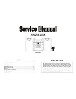
SERVICE MANUAL
This document has been published to be used
for after sales service only.
The contents are subject to change without notice.
SHARP CORPORATION
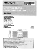
MINI COMPONENT SYSTEM
MODEL
CD-BA250H
CD-BA250H Mini Component System consisting of
CD-BA250H (main unit) and CP-BA250H (speaker system).
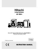
MINI COMPONENT SYSTEM
MODEL
CD-BA2600H
CD-BA2600H Mini Component System consisting of
CD-BA2600H (main unit) and CP-BA2600H (speaker system).
• Note for users in U.K.
Recording and playback of any material may require consent
which SHARP is unable to give. Please refer particularly to the
provisions of Copyright Act 1956, the Dramatic and Musical
Performers Protection Act 1956, the Performers Protection Acts
1963 and 1972 and to any subsequent statutory enactments and
orders.
RTV servis Horvat
Tel: ++385-31-856-842
Tel/fax: ++385-31-856-139
Mob: 098-788-319
www.rtv-horvat-dj.hr