E 1
For Sharp Carousel
®
Built-in Kit
Models RK94S27F or RK94S30F
S = STAINLESS
THIS KIT IS UL APPROVED TO ALLOW CERTAIN MICROWAVE
OVENS TO BE INSTALLED ABOVE ANY ELECTRIC WALL OVEN.
PLEASE SEE THE OPERATION MANUAL REGARDING APPROVED
BUILT-IN APPLICATIONS.
IMPORTANT:
This Built-in Kit is designed for and approved only for those
Sharp Microwave Ovens specifying Built-In Kit RK94S27F or
RK94S30F. Refer to Operation Manual for approved models.
IMPORTANT NOTES TO THE INSTALLER
• PLEASE READ THESE INSTRUCTIONS THOROUGHLY
BEFORE BEGINNING INSTALLATION.
• Observe all governing codes, ordinances, and safety
instructions.
• Be sure to leave these instructions with the consumer.
• Be sure to DISCONNECT THE PLUG of the microwave
oven from the electrical outlet before installing the Built-in
Kit. Remove the Carousel turntable from the oven cavity.
• Because the kit includes metal parts, due caution should
be used in handling and installation to avoid the possibility
of injury.
ITEM
PART NAME
QTY
A
DUCT (A)-1: PDUC-0259WRW0
1
B
DUCT (A)-2: PDUC-B127MRP0
1
C
DUCT (A)-3: PDUC-A734WRW0
1
D
DUCT (B): PDUC-0260WRW0
1
E
DUCT (C): PDUC-A274WRW0
1
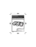
F
BOTTOM DUCT ASSEMBLY:
FDUC-B099MRK1A
1
G
M3.9-16MM PAN HEAD TAPPING
SCREW, ZINC: XOPS740P16000
8
H
WOOD SCREW: XTSS740P20000
2
I
CABINET SCREW: XOTS740P12000
10
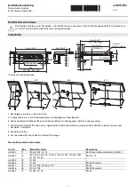
INSTALLATION INSTRUCTIONS
ITEM
PART NAME
QTY
J
FRONT FRAME
RK94S27F: FDECAB229MRK0
RK94S30F: FDECAB227MRK0
1
K
BACK FRAME
RK94S27F: FDECAB255MRK0
RK94S30F: FDECAB226MRK0
1
L
AIR DEFLECTOR
RK94S27F: PREF-B038MRP0
RK94S30F: PREF-B039MRP0
2
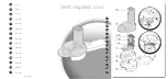
Check list for parts when unpacking.
NOTE:
(J) FRONT FRAME and (K) BACK FRAME are shipped
attached. Snap apart before installation.
A
F
G
H
I
J
K
L
B
C
D
E
DUCT (A)-1
DUCT (A)-2
DUCT (A)-3
DUCT (B)
DUCT (C)