background image

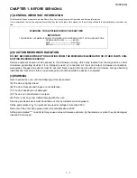
CHAPTER 1. BEFORE SERVICING 

CHAPTER 2. WARNING TO SERVICE PERSONNEL

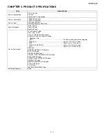
CHAPTER 3. PRODUCT SPECIFICATIONS

CHAPTER 4. APPEARANCE VIEW

CHAPTER 5. OPERATION SEQUENCE

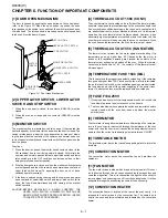
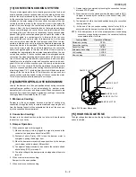
CHAPTER 6. FUNCTION OF IMPORTANT COMPO-
NENTS

CHAPTER 7. TROUBLESHOOTING GUIDE

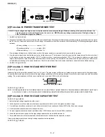
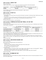
CHAPTER 8. TEST PROCEDURES

CHAPTER 9. TOUCH CONTROL PANEL ASSEMBLY

CHAPTER 10. COMPONENT REPLACEMENT AND 
ADJUSTMENT PROCEDURE

CHAPTER 11. MICROWAVE MEASUREMENT

CHAPTER 12. CIRCUIT DIAGRAMS

Parts List

SX517R990KPJW

CONVECTION

MICROWAVE OVEN

R-990K(S)
R-990K(W)

SERVICE MANUAL

R990K(W)

MODELS

CONTENTS

SHARP CORPORATION

This document has been published to be used
for after sales service only.
The contents are subject to change without notice.

In the interest of user-safety the oven should be restored to its 
original condition and only parts identical to those specified 
should be used.

Summary of Contents for Carousel R-990K

Page 1: ... 10 COMPONENT REPLACEMENT AND ADJUSTMENT PROCEDURE CHAPTER 11 MICROWAVE MEASUREMENT CHAPTER 12 CIRCUIT DIAGRAMS Parts List SX517R990KPJW CONVECTION MICROWAVE OVEN R 990K S R 990K W SERVICE MANUAL R990K W MODELS CONTENTS SHARP CORPORATION This document has been published to be used for after sales service only The contents are subject to change without notice In the interest of user safety the oven...

Page 2: ...re F FUSE F10A 8 3 7 Procedure G TEMPERATURE FUSE AND TERMAL CUT OUT TEST 8 3 8 Procedure H CONVECTION HEATER TEST 8 3 9 Procedure I THERMISTOR TEST 8 3 10 Procedure J MOTOR WINDING TEST 8 4 11 Procedure K HIGH VOLTAGE FUSE TEST 8 4 12 Procedure L NOISE FILTER TEST 8 4 13 Procedure M TOUCH CONTROL PANEL ASSEMBLY TEST 8 4 14 Procedure N KEY UNIT MEMBRANE SWITCH TEST 8 5 15 Procedure O RELAY TEST 8 ...

Page 3: ...e secured Never operate the device without a microwave energy absorbing load attached Never look into an open waveguide or antenna while the device is energized 3 WARNING Never operate the oven until the following points are ensured A The door is tightly closed B The door brackets and hinges are not defective C The door packing is not damaged D The door is not deformed or warped E There is not any...

Page 4: ...nect the supply after the outer case has been removed in this event carry out 3D checks and then disconnect the leads to the pri mary of the power transformer Ensure that these leads remain iso lated from other components and the oven chassis Use insulation tape if necessary When the testing is completed carry out 3D checks and reconnect the leads to the primary of the power transformer REMEMBER T...

Page 5: ...h Control System Clock 1 00 12 59 Timer 0 99 minutes 99 seconds Microwave Power for Variable Cooking Repetition Rate HIGH Full power throughout the cooking time MED HIGH approx 70 of FULL Power MED approx 50 of FULL Power MED LOW DEFROST approx 30 of FULL Power LOW approx 10 of FULL Power HELP pad SENSOR INSTANT ACTION pads MULTI COOK pad REHEAT SENSOR pad CONVECTION COOKING FUNCTION pads EASY DEF...

Page 6: ...EL PAD Press to select microwave power setting If not pressed HIGH is automatically se lected EASY DEFROST PAD Press to defrost meat by entering weight only NUMBER AND TEMPERATURE PADS Press to enter cooking times clock time con vection temperature or to select the Multi Cook menus STOP CLEAR PAD Press to clear during programming Press once to stop operation of oven dur ing cooking press twice to ...

Page 7: ...e following results The circuits to the turntable motor cooling fan motor and high voltage components are de energized the oven lamp remains on and the digital read out displays the time still remaining in the cook cycle when the door was opened 7 The monitor switch is electrically monitoring the operation of the upper latch switch and lower latch switch and is mechanically asso ciated with the do...

Page 8: ...2 The shut off relay RY1 RY5 RY6 energized turning on the oven lamp turntable motor cooling fan motor and convection motor 3 The shut off relay RY4 is energized The damper door is closed from the open position 4 The heater relay RY3 is energized adding the mains supply volt age to the convection heater 5 Now the oven is in the convection cooking condition 6 When the oven temperature reaches the se...

Page 9: ...ected and the food weight is entered by using the number pads the oven will cook according to the special cooking sequence Figure O 2 9 FIRE SENSING FEATURE MICROWAVE MODE This model incorporates a sensing feature which will stop the oven s operation if there is a fire in the oven cavity during microwave cooking This accomplished by the LSI repeatedly measures the voltage across the temperature me...

Page 10: ...er when abnormally high temperatures are reached within the heater unit the oven thermal cut out will open causing the oven to shut down When the oven has cooled temperature the oven thermal cut out closes 5 THERMAL CUT OUT 95C FAN MOTOR The thermal cut out protect the fan motor against over heating If its temperature goes up higher than 95 C because the fan motor is locked or the ventilation oper...

Page 11: ... CLOSE MECHANISM Usually the damper is in the open position except during convection cooking Damper position is set automatically by damper motor damper switch motor cam and damper shaft These components are operated by a signal that judges if microwave cooking or convection cooking operation is selected by the CPU unit 1 Microwave Cooking Damper is in the open position because a portion of coolin...

Page 12: ... E E F G G H I J J J J K M N O O O O O O P Q RE CKCK CK RE L COOKING CONDITION MICROWAVE PROBLEM CONDITION TEST PROCEDURE POSSIBLE CAUSE AND DEFECTIVE PARTS AH SENSOR CONVECTION Home fuse blows when power supply cord is plugged into wall outlet Fuse M8A blows when power cord is plugged into wall outlet Oven lamp does not light with door opened Oven lamp does not light at all Cooling fan motor does...

Page 13: ... test 3 Temperature of the water The initial temperature of the water is 10 1 C 4 Select the initial and final water temperature so that the maximum difference between the final water temperature and the ambient temperature is 5 C 5 Select stirring devices and measuring instruments in order to minimize addition or removal of heat 6 The graduation of the thermometer must be scaled by 0 1 C at minim...

Page 14: ... terminal of the high voltage rectifier and note the reading obtained Reverse the meter leads and note this second reading The normal resistance is infinite in one direction and more than 100 kΩ in the other direction CARRY OUT 4R CHECKS NOTE FOR MEASUREMENT OF THE RESISTANCE OF THE RECTIFIER THE BATTERIES OF THE MEASURING INSTRUMENT MUST HAVE A VOLTAGE AT LEAST 6 VOLTS BECAUSE OTHERWISE AN INFINI...

Page 15: ...g has overheated this may be due to blocked ventilation or locked cool ing fan CARRY OUT 4R CHECKS 8 Procedure H CONVECTION HEATER TEST CARRY OUT 3D CHECKS Before carrying out the following tests make sure the heater is fully cool 1 Resistance of heater Disconnect the wire leads to the heater to be tested Using ohmmeter with low resistance range Check the resistance across the terminals of the hea...

Page 16: ...l the touch control panel assembly is divided into two units Control Unit and Key Unit and troubleshooting by unit replacement is described according to the symptoms indicated 1 Key Unit Note Check key unit ribbon connection before replacement The following symptoms indicate a defective key unit Replace the key unit 1 When touching the pads a certain pad produces no signal at all 2 When touching a...

Page 17: ...connector A and the common terminal of the relay RY1 on the control unit with an A C voltmeter The meter should indicate230 240 volts if not check oven circuit Shut off Cook and Heater Relay Test These relays are operated by D C voltage Check voltage at the relay coil with a D C voltmeter during the microwave cooking operation or convection cooking operation DC voltage indicated Defective relay DC...

Page 18: ...er in a 1000 milliliter measuring cup 2 Place the container on the center of tray in the oven cavity 3 Close the door 4 Touch REHEAT SENSOR pad twice and touch INSTANT COOK START pad Now the oven is in the sensor cooking condition and SOUP SEN SOR and REHEAT will appear in the display 5 The oven will operate for the first 16 seconds without generating microwave energy When the AH sensor is defecti...

Page 19: ...ol panel 6 Reconnect the oven to the power supply and check the sensor cook operation proceed as follows a Touch REHEAT SENSOR pad twice and touch the INSTANT COOK START pad b The control panel is in the sensor cooking operation c After approximately 20 seconds push plunger of select switch This condition is same as judgement by AH sensor d After approximately 3 seconds the display shows X X X X w...

Page 20: ...play units 7 Absolute Humidity Sensor Circuit This circuit detects the humidity of a food which is being cooked to control its automatic cooking 8 Stop Switch A switch to inform the LSI if the door is open or closed 9 Relay Circuit To drive the magnetron heating element fan motor convection motor damper motor turntable motor and light the oven lamp 10 Indicator Circuit Indicator element is a Fluor...

Page 21: ...ff relay RY4 19 P47 OUT Heating element driving signal To turn on and off shut off relay RY3 L level during convection cook ing H level otherwise During convection cooking the signal becomes H level when the temperature of the oven cavity exceeds the predetermined temperature 20 21 P46 P45 OUT Terminal not used 22 P44 OUT Timing signal output terminal for temperature measurement OVEN THERMISTOR H ...

Page 22: ...7 P23 OUT Segment data signals The relation between signals and indicators are as follows Signal Segment Signal Segment Signal Segment Signal Segment P23 P1 P17 P5 P13 P9 P07 P13 P22 P2 P16 P6 P12 P10 P06 P14 P21 P3 P15 P7 P11 P11 P05 P15 P20 P4 P14 P8 P10 P12 P04 P16 38 40 P22 P20 OUT Segment data signal Signal similar to P23 41 P17 OUT Segment data signal Signal similar to P23 Key strobe signal ...

Page 23: ...or cooking proceeds the food is heated to generate moisture by which the resistance balance the bridge circuit is deviated to increase the voltage available atAN6 terminal of the LSI Then the LSI observes that voltage at AN6 terminal and compares it with its initial value and when the comparison rate reaches the pre set value fixed for each menu to be cooked the LSI causes the unit to stop sensor ...

Page 24: ...n some models the power supply cord between the touch control panel and the oven proper is long enough that they may be sepa rated from each other For those models therefore it is possible to check and repair the controls of the touch control panel while keep ing it apart from the oven proper in this case you must short both ends of the door sensing switch on PWB of the touch control panel with a ...

Page 25: ...dingly 3 Soldering As the melting point of lead free solder Sn Ag Cu is higher and has poorer wettability flow to prevent damage to the land of the PWB extreme care should be taken not to leave the bit in contact with the PWB for an extended period of time Remove the bit as soon as a good flow is achieved The high content of tin in lead free solder will cause premature corrosion of the bit To redu...

Page 26: ...val procedures To prevent an electric shock take the following precautions 1 Before wiring 1 Disconnect the power supply cord 2 Open the door and block it open 3 Discharge the high voltage capacitor and wait for 60 seconds 2 Don t let the wire leads touch to the following parts 1 High voltage parts Magnetron Power transformer High voltage capacitor High voltage rectifier assembly and High voltage ...

Page 27: ...he waveguide with care so the mag netron antenna should not hit by any metal object around the antenna CAUTION WHEN REPLACING THE MAGNETRON BE SURE THE R F GASKET IS IN PLACE ANDTHE MAGNETRON MOUNTING SCREWS ARE TIGHTENED SECURELY 5 HIGH VOLTAGE RECTIFIER ASSEMBLY REMOVAL 1 CARRY OUT 3D CHECKS 2 Remove one 1 screw holding the high voltage rectifier terminal to the capacitor holder 3 Disconnect the...

Page 28: ...otor to the mounting plate of the oven cavity bottom 5 Pull the turntable coupling out of the oven cavity 6 Turntable coupling and motor will be free 11 CONVECTION MOTOR REMOVAL 1 CARRY OUT 3D CHECKS 2 Disconnect wire leads from the convection motor Remove the convection fan belt and pulley M 3 Remove two 2 screws holding the convection motor mounting angle to the heater duct and base cabinet 4 Ta...

Page 29: ...3 screws 5 Connect the wire leads to the fan motor and the thermal cut out referring to the pictorial diagram 14 CORD HOLDER REMOVAL 1 Remove the one 1 special screw holding the cord holder to the rear cabinet using the special driver LHSTIX DLR4 100T 2 Now the cord holder is free NOTE When securing or loosening the special screw LHSTIX DLR4 100T type screw driver should be used 15 POWER SUPPLY CO...

Page 30: ...e oven cavity front flange and adjust the latch hook position 2 After adjustment check the following 1 The in and out play of the door remains less than 0 5mm at latched position 2 The stop switch and lower latch switch interrupt the circuit before the door can be opened 3 The upper latch switch contacts open when the door is opened 4 The monitor switch contacts close when the door is opened 5 Re ...

Page 31: ...p NOTE As the engaging part of choke cover and door panel are pro vided at several places do not force any particular part 2 Insert an putty knife thickness of about 0 5mm into the gap between the choke cover and corner portion of door panel as shown Figure C 2 to free engaging parts 3 Lift up choke cover 4 Now choke cover is free from door panel Figure C 2 Door Disassembly DOOR PANEL 5 Remove the...

Page 32: ...mance standard for microwave ovens must be used for testing Recommended instruments are NARDA 8100 NARDA 8200 HOLADAY HI 1500 SIMPSON 380M 2 Place the oven tray into the oven cavity 3 Place the load of 275 15ml of water initially at 20 5 C in the centre of the oven tray The water container should be a low form of 600 ml beaker with inside diameter of approx 8 5cm and made of an electrically non co...

Page 33: ...ER LATCH SWITCH TEMPERATURE FUSE 150 C MAGNETRON THERMAL CUT OUT 95 C FAN THERMAL CUT OUT 145 C MAGNETRON 230 240V 50Hz FM COM RY1 E 5 E 4 E 3 E 2 E 1 F 3 F 2 F 1 RY3 N O RY1 COM RY3 COM RY2 N O RY2 N O RY3 A 9 A 7 CM DM OL FUSE F10A RY2 TTM H V FUSE 0 75A OR NOTE indicates components with potentials above 250V THERMAL CUT OUT 150 C CONV NOISE FILTER MONITOR SWITCH LOWER LATCH SWITCH OVEN LAMP FAN...

Page 34: ...TOR 1 13μ AC 2100V RY4 RY5 RY6 RY1 UPPER LATCH SWITCH TEMPERATURE FUSE 150 C MAGNETRON THERMAL CUT OUT 95 C FAN THERMAL CUT OUT 145 C MAGNETRON 230 240V 50Hz FM COM RY1 E 5 E 4 E 3 E 2 E 1 F 3 F 2 F 1 RY3 N O RY1 COM RY3 COM RY2 N O RY2 N O RY3 A 9 A 7 CM DM OL FUSE F10A RY2 TTM H V FUSE 0 75A OR NOTE indicates components with potentials above 250V THERMAL CUT OUT 150 C CONV NOISE FILTER MONITOR S...

Page 35: ...ANSFORMER CONVECTION MOTOR GRN COM N O GRY GRY WHT GRY PPL WHT WHT WHT WHT RED WHT WHT N O COM PNK PNK RED GRY RED RED 2 1 BRN COM N O ORG PNK LOWER LATCH SWITCH MONITOR SWITCH COM N C GRY GRY ORG BLK AH SENSOR RED WHT 1 2 3 CN F 2 RY3 RY2 CN A THERMAL CUT OUT 95ûC FAN MOTOR RED BLK RED GRY R E D WHT R E D R E D RY1 RY6 T1 1 6 5 4 2 3 1 3 5 7 9 N O N O N O COM COM COM RY3 N O RY3 COM RY2 N O BRN R...

Page 36: ...ERMISTOR AH SENSOR OVEN LAMP TURNTABLE MOTOR RY6 RY2 D30 RY3 RY1 R31 4 7k R51 4 7k R62 75kF CF1 4 19MHz C70 330pF x 4 A B C C30 C50 C60 D3 D4 D7 Q1 2SB1238 Q4 DTA123ES Q3 KRA101M Q90 KRA101M Q40 KRA101M Q21 KRA101M Q22 KRA101M Q24 KRA101M Q25 KRA101M Q23 KRA101M Q26 KRC243M Q20 KRA101M R10 18 1w CONTROL UNIT C10 0 1μ 50v VP VP F F 8G 31 32 1 2 29 MIX CONV DEFROST SENSOR COOK KG HELP R90 100k IC2 I...

Page 37: ... C10 C81 C80 C45 R 47 C46 C47 R 48 R 49 CN D C N G C N G C N F C N E ONL Y 9X58P J C7 C9 C5 C6 C21 C4 C2 C22 C1 R 3 C3 C60 C50 C30 R 45 R 91 R 92 R 93 R 64 R 80 R 81 R 73 D70 D71 D72 D73 D74 D75 D76 D77 R 72 R 71 R 70 R 79 R 78 R 77 R 76 R 75 R 74 R 86 J 8 R 90 R 7 R 100 R 40 DA MP S W DOOR S W OV E N T E MP R 50 R 51 R 31 R 30 P OWE R T R A NS P OWE R OL T T M R 62 C 20 26 C N A ZD2 R 2 D3 D4 D1 ...

Page 38: ...R990K W 12 6 MEMO ...

Page 39: ...NUMBER 2 REF NO 3 PART NO 4 DESCRIPTION Parts marked may cause undue microwave exposure Parts marked are used in voltage more than 250V 1 OVEN PARTS 2 DOOR AND CONTROL PANEL PARTS 3 OTHER INDEX 4 3 TURNTABLE TRAY 6 7 OPERATION MANUAL 6 3 COOK BOOK 4 2 TURNTABLE SUPPORT TRAY PACKING FOAM SPADPA198WRE0 DOOR PROTECTION SHEET SPADPA178WRE0 MICROWAVE OVEN TOP PAD ASSEMBLY FPADBA362WRK0 PLASTIC BAG SSAK...

Page 40: ...7 19 1 1 7 16 7 1 1 8 1 10 4 21 1 3 7 19 4 26 4 27 4 18 4 20 7 9 7 16 4 19 1 9 1 14 7 17 4 17 7 23 7 6 1 21 4 40 4 14 7 18 2 4 2 3 2 2 3 1 7 22 4 28 7 7 1 23 4 16 4 24 4 24 7 20 7 20 1 10 4 38 4 6 7 15 4 38 4 39 7 2 6 8 7 2 4 34 4 25 4 13 6 4 7 16 2 3 1 11 7 22 7 19 4 5 1 3 1 20 4 31 7 1 2 5 7 13 7 5 4 11 7 2 2 2 2 9 2 8 7 8 4 35 7 8 A TO OVEN BASE PLATE x2 x2 x2 x2 x 5 x3 x4 x5 x3 A x3 x4 x2 x3 x...

Page 41: ...rntable motor 1 16 RMOTEA303WRE0 AX Cooling fan motor 1 17 RMOTEA284WRE0 AZ Convection motor 1 18 QFS IA002WRE0 AQ High voltage fuse 0 75A 1 19 RTHM A121WRE0 AK Thermal cut out 150C Conv 1 19 RTHM A085WRE0 AL Thermal cut out 150C Conv Interchnageable 1 19 RTHM A099WRE0 Thermal cut out 150C Conv Interchnageable for 1 20 RTHM A117WRE0 AK Thermal cut out 95C Fan 1 20 RTHM A079WRE0 AL Thermal cut out ...

Page 42: ...KR A171WRW0 AE Magnetron air guide 4 42 PFPF A064WRE0 AF Thermal protection sheet 4 43 PCUSGA353WRP0 AH Cushion MISCELLANEOUS 6 4 FW VZB635WRE0 AT Thermistor harness 6 8 TCAUHA214WRR0 AF K caution label 6 9 TLABNA226WRR0 AE Menu label SCREWS NUTS AND WASHERS 7 1 XOTWW40P10000 AA Screw 4mm x 10mm 7 2 XOTS740P12000 AA Screw 4mm x 12mm 7 3 XCTWW40P08000 AA Screw 4mm x 8mm 7 4 XHTS740P08RV0 AG Screw 4...

Page 43: ... may be different than illustration 6 4 6 1 6 5 6 7 6 2 6 3 6 6 3 5 3 4 3 7 3 3 3 6 3 1E 3 1F 3 1 3 8 3 6 3 6 7 18 7 18 5 3 5 15 5 1 5 6 10 3 7 5 12 5 12 5 11 5 7 5 11 5 11 5 11 5 2 5 8 5 6 5 10 5 5 5 4 5 9 5 13 3 2 3 2 3 3 2 2 3 2 4 5 14 3 2 1 3 2 7 3 2 6 3 2 5 ...

Page 44: ...r glass 5 3 GCOVHA155WRF0 AP Choke cover 5 4 GWAKPB014WRFZ BD Door frame 5 5 GCOVAA372WRPZ BA Door decoration U R 990K W 5 5 GCOVAA354WRPZ BA Door decoration U R 990K S 5 6 LANGKA851WRT0 AF Latch angle 5 7 LSTPPA169WRF0 AH Latch head 5 8 MSPRTA192WRE0 AC Latch head spring 5 9 LANGKB163WRWZ AK Thermal plate U 5 10 LANGKB164WRWZ AK Thermal plate R 5 11 XCPS740P08000 AB Screw 4mm x 8mm 5 12 XEBS730P0...

Page 45: ...VSKRA101M 3 AB Transistor KRA101M Q90 VSKRA101M 3 AB Transistor KRA101M R2 VRD B12HF471J AA Resistor 470 ohm 1 2W R3 VRD B12HF331J AA Resistor 330 ohm 1 2W R4 VRD B12HF751J AA Resistor 750 ohm 1 2W R7 8 VRD B12EF472J AA Resistor 4 7k ohm 1 4W R10 11 VRS B13AA180J AA Resistor 18 ohm 1W R30 VRD B12EF153J AA Resistor 15k ohm 1 4W R31 VRD B12EF472J AA Resistor 4 7k ohm 1 4W R40 VRD B12EF332J AA Resist...

Page 46: ...31WRF0 1 2 2 AE MSPRCA050WRE0 2 3 2 3 AB MSPRTA192WRE0 2 5 8 AC N NBLTKA005WRE0 1 4 36 AF NCPL A021WRF0 1 4 22 AE NFANJA020WRE0 1 4 32 AE NFANMA019WRW0 1 4 9 AE NPLYBA025WRF0 1 4 10 AC NSFTTA042WRE0 2 3 5 AE NSFTTA114WRE0 1 4 18 AB NTNT A019WRH0 1 4 3 AT P PCOVPA301WRE0 1 4 23 AE PCUSGA236WRP0 1 4 40 AC PCUSGA353WRP0 1 4 43 AH PCUSGA381WRP0 2 3 1F AG PCUSGA410WRP0 1 4 21 AD PCUSGA537WRPZ 2 5 13 AD...

Page 47: ...R3 AA VRD B12HF471J 3 R2 AA VRD B12HF751J 3 R4 AA VRN B12EK101F 3 R63 AA VRN B12EK222F 3 R64 AA VRN B12EK753F 3 R62 AA VRS B13AA180J 3 R10 11 AA VRS B13AA331J 3 R100 AA VS2SB1238 3 3 Q1 AA VSDTA123ES 3 3 Q4 AA VSKRA101M 3 3 Q3 AB 3 Q40 AB 3 Q90 AB 3 Q20 23 AB VSKRA223M 3 3 Q24 25 AB VSKRC243M 3 3 Q26 AB PARTS CODE No PRICE RANK NEW MARK PART RANK X XBPS730P14K00 1 7 9 AC XBPS740P06KS0 1 7 14 AD XB...

Page 48: ...ut prior written permission of the publisher COPYRIGHT XXXX BYSHARP CORPORATION ALL RIGHTS RESERVED COPYRIGHT 2005 BY SHARP CORPORATION ALL RIGHTS RESERVED No part of this publication may be reproduced stor ed in retrieval systems or transmitted in anyform or by any means electronic mechanical photocopy ing recording or other wise without prior written permission of the publisher ...

Reviews: