


This document has been published to be used for
after sales service only.
The contents are subject to change without notice.
Parts marked with “
“ are important for maintaining the safety of the set.
Be sure to replace these parts with specified ones for maintaining the safety and performance of the set.
SHARP CORPORATION
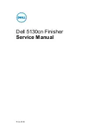
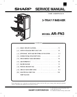
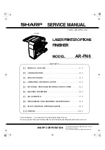
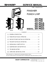
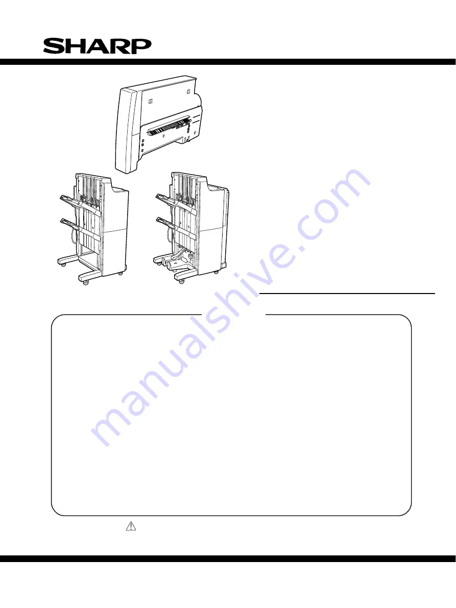
SERVICE MANUAL
FINISHER
PUNCH UNIT
AR-FN8
AR-FN9
AR-PN2A
AR-PN2B
AR-PN2C
MODEL
AR-PN2D
[1]
GENERAL DESCRIPTION . . . . . . . . . . . . . . . . . . . . . . . . . . . . . 1-1
[2]
FINISHER UNIT BASIC OPERATION. . . . . . . . . . . . . . . . . . . . . 2-1
[3]
SADDLE STICHER UNIT BASIC OPERATION . . . . . . . . . . . . . 3-1
[4]
PUNCHER UNIT BASIC OPERATION . . . . . . . . . . . . . . . . . . . . 4-1
[5]
MECHANICAL CONSTRUCTION . . . . . . . . . . . . . . . . . . . . . . . . 5-1
[6]
MAINTENANCE AND INSPECTION. . . . . . . . . . . . . . . . . . . . . . 6-1
[7]
TROUBLESHOOTING . . . . . . . . . . . . . . . . . . . . . . . . . . . . . . . . 7-1
[8]
UNPACKING AND INSTALLATION . . . . . . . . . . . . . . . . . . . . . . . 8-1
CODE : 00ZARFN8//A1E
AR-FN8
AR-PN2
AR-FN9
CONTENTS
Summary of Contents for AR-FN8
Page 3: ...ii ...
Page 77: ...2 41 CHAPTER 2 FINISHER UNIT BASIC OPERATION eight sensor PS1 Paper Figure 2 240 ...
Page 124: ...3 31 CHAPTER 3 SADDLE STITCHER UNIT BASIC OPERATION Cam Mount Figure 3 404 ...
Page 210: ...7 12 CHAPTER 7 TROUBLESHOOTING 2 Microswitches MS1 MS4 MS3 MS5 MS6 MS2 MS8 Figure 7 302 ...
Page 212: ...7 14 CHAPTER 7 TROUBLESHOOTING 3 Motors M1 M9 M8 M2 M7 M3 M4 M5 M6 Figure 7 303 ...
Page 220: ...7 22 CHAPTER 7 TROUBLESHOOTING 3 Motors M7S M8S M2S M1S M4S M5S M3S M6S Figure 7 308 ...
Page 249: ...CHAPTER 8 UNPACKING AND INSTALLATION I FINISHER 8 1 II PUNCH UNIT 8 6 ...
Page 260: ...B FINISHER UNIT CIRCUIT DIAGRAM 1 3 SWING_UNIT A 3 ...
Page 261: ...A 4 ENTRANCE_MT ENTRANCE_S ...
Page 262: ...A 5 ...
Page 263: ...FINISHER UNIT CIRCUIT DIAGRAM 2 3 A 6 ...
Page 264: ...FINISHER UNIT CIRCUIT DIAGRAM 3 3 A 7 ...
Page 265: ...A 8 ...
Page 266: ...A 9 ...
Page 267: ...C FINISHER CONTROLLER PCB 1 10 A 10 ...
Page 268: ...FINISHER CONTROLLER PCB 2 10 A 11 ...
Page 269: ...A 12 ...
Page 270: ...A 13 ...
Page 271: ...FINISHER CONTROLLER PCB 3 10 A 14 ...
Page 272: ...FINISHER CONTROLLER PCB 4 10 A 15 ...
Page 273: ...A 16 ...
Page 274: ...A 17 ...
Page 275: ...FINISHER CONTROLLER PCB 5 10 A 18 ...
Page 276: ...FINISHER CONTROLLER PCB 6 10 A 19 ...
Page 277: ...ENTRANCE_S0 ENTRANCE_SENS A 20 ...
Page 278: ...A 21 ...
Page 279: ...FINISHER CONTROLLER PCB 7 10 A 22 ...
Page 280: ...FINISHER CONTROLLER PCB 8 10 A 23 ...
Page 281: ...A 24 ...
Page 282: ...A 25 ...
Page 283: ...FINISHER CONTROLLER PCB 9 10 A 26 ...
Page 284: ...FINISHER CONTROLLER PCB 10 10 A 27 ...
Page 285: ...A 28 ...
Page 286: ...A 29 ...
Page 287: ...D SADDLE STITCHER UNIT CIRCUIT DIAGRAM 1 2 A 30 ...
Page 288: ...GUIDE_MT SADDLE STITCHER UNIT CIRCUIT DIAGRAM 2 2 A 31 ...
Page 289: ...STPL_UNIT1 Rear STPL_UNIT2 Front A 32 ...
Page 290: ...PUSHCW A 33 ...
Page 291: ...E SADDLE STITCHER UNIT PCB 1 8 FOLD_NUKE FOLD_HP A 34 ...
Page 292: ...SADDLE STITCHER UNIT PCB 2 8 A 35 ...
Page 293: ...A 36 ...
Page 294: ...ENTRANCE_COVER FOLDDIR0 FOLDPWM0 FOLDDIR1 A 37 ...
Page 295: ...SADDLE STITCHER UNIT PCB 3 8 FOLD MTR A 38 ...
Page 296: ...SADDLE STITCHER UNIT PCB 4 8 A 39 ...
Page 297: ...A 40 ...
Page 298: ...A 41 ...
Page 299: ...SADDLE STITCHER UNIT PCB 5 8 A 42 ...
Page 301: ...P P FOLD_CLK PUSH_CLK0 NS PUSH CLK SENS FOLD CLK A 44 ...
Page 302: ...STAPLE UNIT SENNS ENTRANCE_COVER A 45 ...
Page 303: ...SADDLE STITCHER UNIT PCB 7 8 ENNS A 46 ...
Page 304: ...SADDLE STITCHER UNIT PCB 8 8 PUSHCW PUSHPWM PUSHCCW FOLD_HP FOLD_OUT FOLD_HP A 47 ...
Page 305: ...A 48 ...
Page 306: ...A 49 ...
Page 307: ...For FINISHER_CONTROLLER_PCB F PUNCHER UNIT OPTION CIRCUIT DIAGRAM 1 1 A 50 ...
Page 308: ...G PUNCH DRIVER PCB 1 2 A 51 ...
Page 309: ...A 52 ...
Page 310: ...A 53 ...
Page 311: ...PUNCH DRIVER PCB 2 2 A 54 ...
Page 313: ...APPENDIX A 56 ...