background image

This document has been published to be used for

after sales service only.

The contents are subject to change without notice.

Parts marked with “

“ are important for maintaining the safety of the set. 

Be sure to replace these parts with specified ones for maintaining the safety and performance of the set.

SHARP CORPORATION

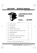
LASER PRINTER OPTIONS

FINISHER

MODEL

AR-FN6

CODE : 00ZARFN6//A1E

[1]

PRODUCT OUTLINE  . . . . . . . . . . . . . . . . . . . . . . . . . . . . . . . . 1 - 1

[2]

CONFIGURATION. . . . . . . . . . . . . . . . . . . . . . . . . . . . . . . . . . . 2 - 1

[3]

SPECIFICATIONS . . . . . . . . . . . . . . . . . . . . . . . . . . . . . . . . . . . 3 - 1

[4]

UNPACKING AND INSTALLATION . . . . . . . . . . . . . . . . . . . . . . 4 - 1

[5]

EXTERNAL VIEWS AND INTERNAL STRUCTURES  . . . . . . . 5 - 1

[6]

MACHINE OPERATION  . . . . . . . . . . . . . . . . . . . . . . . . . . . . . . 6 - 1

[7]

ADJUSTMENTS . . . . . . . . . . . . . . . . . . . . . . . . . . . . . . . . . . . . 7 - 1

[8]

DISASSEMBLY AND ASSEMBLY, MAINTENANCE . . . . . . . . . 8 - 1

[9]

BLOCK DIAGRAM, WIRING DIAGRAM . . . . . . . . . . . . . . . . . . 9 - 1

[10] OTHERS . . . . . . . . . . . . . . . . . . . . . . . . . . . . . . . . . . . . . . . . . 10 - 1

CONTENTS

AR-FN6

Summary of Contents for AR-FN6

Page 1: ...ified ones for maintaining the safety and performance of the set SHARP CORPORATION LASERPRINTEROPTIONS FINISHER MODEL AR FN6 CODE 00ZARFN6 A1E 1 PRODUCT OUTLINE 1 1 2 CONFIGURATION 2 1 3 SPECIFICATIONS 3 1 4 UNPACKING AND INSTALLATION 4 1 5 EXTERNAL VIEWS AND INTERNAL STRUCTURES 5 1 6 MACHINE OPERATION 6 1 7 ADJUSTMENTS 7 1 8 DISASSEMBLY AND ASSEMBLY MAINTENANCE 8 1 9 BLOCK DIAGRAM WIRING DIAGRAM ...

Page 2: ...ed together 3 This unit cannot be installed together with the male bin stacker AR MS1 and the upper exit tray extension AR TE4 Applicable models AR P350 P450 AR M350 M450 DM 3500 3501 4500 4501 DM 3551 4551 AR D14 AR MU1 AR DC1 AR D13 AR TE4 AR FN6 AR MS1 Output units AR FN6 Scanner rack Finisher Any of the units must be installed together Multi purpose drawer Stand 3 x 500 sheet paper drawer Stan...

Page 3: ...ray Not provided Lower Tray Provided Exit tray full detection Upper tray Provided Lower tray Provided Power consumption Less than about 67 3W Power source Supplied from the optional power source DC24V 2 7A DC5V 0 5A External dimensions WxDxH Occupied dimensions WxD Weight Approx 23kg Offset stack Offset volume 25mm Paper size to be stapled A4 B5 8 5 x11 Ability of stapler Max of pages for staple 3...

Page 4: ...he cabinet attached to the right side of the main unit of the printer and remove the cabinet 2 Mount screw B to the position shown in the illustration 3 Attach the finisher 1 Remove the paper exit actuator from the main unit of the printer 2 Raise the relay unit at the side of the finisher 3 Put the finisher on the stand paper drawer Put the finisher on the stand paper drawer temporarily and push ...

Page 5: ...ver and then remove the AC inlet cover 2 Remove the AC cord of the power supply unit from the inlet connector of the main unit of the printer Remove the four screws that fix the rear cabinet and then remove the rear cabinet If a multi purpose drawer has been installed steps 7 to 9 are needed If a stand MPD 2000 sheet paper drawer or stand 3 x 500 sheet paper drawer has been installed proceed to st...

Page 6: ...s the harness of the finisher between the power supply unit and the frame of the stand paper drawer and connect it to the connector of the power supply unit 2 Fit the snap band attached to the finisher at the position shown in the illustration to fix the harness 11 Attach the rear cabinet of the stand paper drawer 1 Pass the AC cord of the power supply unit as shown in the illustration and fix the...

Page 7: ...AL VIEWS AND INTERNAL STRUCTURES 1 5 EXTERNAL VIEWS AND INTERNAL STRUCTURES A External view B Internal structure TBD 1 Top cover 2 Knob 3 Top tray 4 Staple compiler 5 Offset tray 6 Front cover 7 Staple unit 2 3 5 1 ...

Page 8: ...STTM Staple Unit Turn Motor Stapler rotation 9 EVM Elevator Motor Offset tray up down shift 10 T2OM Tray 2 Ouput Motor Drive of paper exit paddler to offset tray 11 FGS Finisher Gate Solenoid Paper entry gate selection 12 SCGS Staple Compiler Gate Solenoid Staple paper entry gate selection 13 SCRS Staple Compiler Rolor Solenoid Belt roller press release selection 14 PPS Paper Push Solenoid Paper r...

Page 9: ...ensor 1 Staple rotation home position detection Detected by combination of STTHP1 and STTHP2 12 STTHP2 Staple Turn Home Position Sensor 2 Staple rotation home position detection 13 STUHP Staple Turn Home Position Sensor Staple shift home position detection H Home position 14 POD Paper Out Detect Sensor Paper exit detection L Paper loaded 15 T2UP Tray 2 Upper Detect Sensor Offset tray upper limit p...

Page 10: ... appear 1 GROUP key If this function is selected all copies of the same original will be grouped 2 STAPLE SORT key If this function is selected sorted copies will be stapled and delivered to the offset tray not offset stacked 3 SORT key If this function is selected each set of copies will be sequentially delivered 4 Icon display The icon of the selected function sort staple sort or group is displa...

Page 11: ...of paper cannot be stapled Pre punched paper transparency film heavy paper label envelope postcard Image data or original Result First page front side Second page reverse side Two sides Portrait orientation printing Left binding Top binding Right binding Left binding Top binding Right binding One position stapling Two position stapling One position stapling Two position stapling One position stapl...

Page 12: ...justment value with 0 9 keys and press START key and the menu below will be displayed Adjustment range 40 60 SIM 3 6 Jogger moving When the stopper is turned on and finisher joggers F R move to and stop at the positions shown in the table below 3 When the joggers F R stop open the door and load A4 LT paper in the alignment tray and check the jogger width visually 4 When the jogger width is too wid...

Page 13: ...k Transport section Transport rollers De curler roller Transport paper guides Drive section Gears Specified position Belts Other Sensors Discharge brush Staple un Replace UN at 100K staple Staple cartridge User replacement for every 3000pcs Unit name Part name When calling 50K 100K 150K 200K 250K 300K 350K 400K Remark Transport section Transport rollers De curler roller Transport paper guides Driv...

Page 14: ... from the printer fold the transport unit as described below If not the frame may be bent causing a breakdown of the machine B External cabinet C Transport unit 1 Gate solenoid 2 Transport roller 1 2 1 2 2 3 4 4 5 5 5 6 7 No Parts name Job item cycle 1 Transport rollers Clean 100K 2 Transport paper guide 100K 1 1 2 3 1 2 1 2 3 4 5 4 ...

Page 15: ... DISASSEMBLY AND ASSEMBLY MAINTENANCE 3 3 Upper open close sensor 4 Upper cover 5 Paper entry sensor 6 Transport roller 1 2 3 4 5 6 3 2 1 1 3 4 1 2 3 5 4 6 7 8 9 10 11 5 4 3 4 3 2 1 3 2 1 1 2 3 1 1 1 4 5 3 2 ...

Page 16: ...MBLY AND ASSEMBLY MAINTENANCE 4 D Rear side of the unit 1 Main motor 2 Main control PWB 3 Staple shift motor 4 Elevator motor Staple rotation motor 5 Pressure release solenoid 2 1 1 2 2 3 3 3 1 4 1 2 1 1 2 2 3 3 1 2 ...

Page 17: ...AR FN6 DISASSEMBLY AND ASSEMBLY MAINTENANCE 5 E Stapler 1 Stapler unit No Parts name Job item cycle 1 Staple UN 2 Staple cartridge 1 2 3 4 5 6 1 2 1 1 2 3 4 ...

Page 18: ...AR FN6 DISASSEMBLY AND ASSEMBLY MAINTENANCE 6 F Inside of the unit 1 Jogger motor 2 Pusher motor 3 Elevator unit 1 2 3 4 4 5 7 6 1 2 1 1 2 3 4 6 5 7 8 7 4 4 4 1 1 2 2 1 2 1 1 2 2 3 3 ...

Page 19: ...SSEMBLY MAINTENANCE 7 G Right side of the unit Paper exit side 1 External cabinet 2 Paper exit roller 3 Paper exit paddler No Parts name Job item cycle 1 Transport roller clear 100K 1 2 3 4 4 6 7 5 2 3 1 4 2 3 1 3 4 2 1 1 2 1 ...

Page 20: ...solenoid 2 Gate solenoid 3 Paper holding solenoid 4 Compiler paper entry gate solenoid I Gears Clutch J Belts No Parts name Job item cycle 1 2 1 2 2 5 3 4 1 2 1 2 No Parts name Job item cycle 1 Gears Lubricate 100K No Parts name Job item cycle 1 Belts clear 300K 1 3 2 4 6 8 9 10 7 5 ...

Page 21: ... 2 2SB1198K x4 24V SCGS PPS 24V 24V SPS T2S 24V SCRS 24V FGS 24V TD62003AP GND1 GND2 FG 3 3 2 A C A C P70 P72 Y Y SEL0 SEL2 T1PF 5V 1 B3 1 D3 DSW1 DSW2 Door SWitch 2 SCPD 5V 5V PPD JRHP 5V 5V JFHP T2PD 5V 5V T2UP T2DN 5V 5V POD SCID2 5V 5V PID SCID 5V PSHP 5V 5V STTHP2 5V 5V DOPD 1 D3 STTHP1 A8 A16 AD0 AD7 LATCH EPROM 1M 74HC373 LE A8 A16 A0 A7 D0 D7 M27C1001 OE A8 A16 AD0 AD7 A0 A7 STM STHP STNC ...

Page 22: ...Y OR RD BL RD BR RD BL RD BR OR GY PK OR OR GY GY PL BR RD GY BL PL BR OR GY BL OR PL GY RD BR RD RD BL PL BR PK RD RD BL PL BR PK RD RD BL PL BR PK RD RD OR GY GY GY GY GY GY GY GY GY OR OR OR OR OR OR OR OR RD RD BL PL BR PK BL BL PL BR PK BL PL OR GY BL OR PL GY RD BR RD BL BL RD GY RD BR RD RD BR OR PK GY OR PL GY OR BR GY RD BR RD BR RD RD RD RD OR YE BR BK OR YE BR OR YE BR BK BK RD 1 3 2 PO...

Page 23: ...AR FN6 OTHERS 1 10 OTHERS A SF MAIN PWB TF UN PIN CPWBN1478FC32 ...

Page 24: ...AR FN6 OTHERS 2 ...

Page 25: ...owledgments Windows and Windows NT are trademarks of Microsoft Corporation in the U S A and other countries IBM and PC AT are trademarks of International Business Machines Corporation PCL is a trademark of Hewlett Packard Company Pentium is a registered trademark of Intel Corporation All other trademarks and copyrights are the property of their respective owners SHARP CORPORATION Digital Document ...

Reviews: