background image

CODE: 00ZARFN3//A1E

3-TRAY FINISHER

MODEL

 AR-FN3

This document has been published to be used
for after sales service only.
The contents are subject to change without notice.

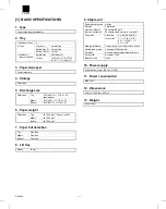
[ 1 ] BASIC SPECIFICATIONS  . . . . . . . . . . . . . . . . . . . . . . . . . . . . . 1-1

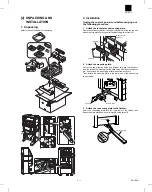
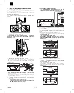
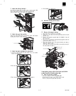
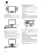
[ 2 ] UNPACKING AND INSTALLATION  . . . . . . . . . . . . . . . . . . . . . 2-1

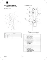
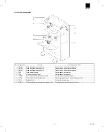
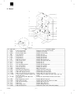
[ 3 ] EXTERNAL VIEW AND INTERNAL STRUCTURE . . . . . . . . . . 3-1

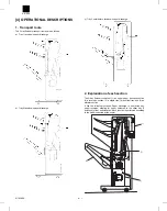
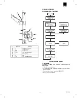
[ 4 ] OPERATIONAL DESCRIPTIONS  . . . . . . . . . . . . . . . . . . . . . . . 4-1

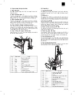
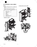
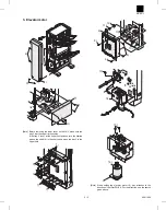
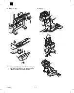
[ 5 ] DISASSEMBLY AND ASSEMBLY  . . . . . . . . . . . . . . . . . . . . . . 5-1

[ 6 ] ADJUSTMENTS  . . . . . . . . . . . . . . . . . . . . . . . . . . . . . . . . . . . . 6-1

[ 7 ] MAINTENANCE . . . . . . . . . . . . . . . . . . . . . . . . . . . . . . . . . . . . . 7-1

[ 8 ] TROUBLESHOOTING . . . . . . . . . . . . . . . . . . . . . . . . . . . . . . . . 8-1

[ 9 ] CIRCUIT DESCRIPTIONS  . . . . . . . . . . . . . . . . . . . . . . . . . . . . 9-1

[10] ELECTRICAL SECTION  . . . . . . . . . . . . . . . . . . . . . . . . . . . . . 10-1

PARTS GUIDE

CONTENTS

AR-FN3

Summary of Contents for AR-FN3

Page 1: ... subject to change without notice 1 BASIC SPECIFICATIONS 1 1 2 UNPACKING AND INSTALLATION 2 1 3 EXTERNAL VIEW AND INTERNAL STRUCTURE 3 1 4 OPERATIONAL DESCRIPTIONS 4 1 5 DISASSEMBLY AND ASSEMBLY 5 1 6 ADJUSTMENTS 6 1 7 MAINTENANCE 7 1 8 TROUBLESHOOTING 8 1 9 CIRCUIT DESCRIPTIONS 9 1 10 ELECTRICAL SECTION 10 1 PARTS GUIDE CONTENTS AR FN3 ...

Page 2: ...8 g m2 Bottom 64 128 g m2 7 Paper full detection Top Provided Middle Provided Bottom Provided 8 Lift tray Off set 30 mm 9 Staple unit Paper discharge tray Lift tray Storage Face down Number of sheets that can be stapled 50 sheets 80 g m2 25 sheets when the size is over A4 LT Paper size AB series A3 B4 A4 A4R B5 Inch series 11 17 8 5 14 8 5 13 8 5 11 8 5 11 R Stapling reference 1 point front 1 poin...

Page 3: ... out the two mounting holes the leftmost hole and the third hole from the left at the lower part of the desk using a Phillips screwdriver etc and remove the burrs using a flat blade screwdriver etc Then attach the mounting plate to the lower part of the desk using two screws A 3 Attach the connecting plate to the finisher Insert the connecting plate into the lower part of the finisher and attach t...

Page 4: ...knob A and knob B clockwise so that the clearances at the upper part and lower part are uniform If the clearance is wide at the upper part Turn knob A and knob B counterclockwise so that the clearances at the upper part and lower part are uniform 2 If the guide pin of the lock plate does not match the connecting hole of the finisher Turn the knobs at the lower part of the finisher to adjust the he...

Page 5: ...the exit unit of the copier until it stops 2 Remove the 2 exit area cover securing screws and remove the exit area cover 3 Remove the 2 transport springs which are attached to the exit area paper guide 4 Store the 2 removed transport springs by hanging them on the exit unit front frame shown in Fig 1 5 Attach the exit area cover to its original position and secure it using the 2 securing screws At...

Page 6: ...0 6 Paper discharge pressure release roller 7 Paper discharge gate 3 F50 8 Paper discharge roller 4 9 Paper discharge roller 3 10 Follower roller FN3 11 Vertical transport roller 3 12 Paper discharge roller 2 13 Paper discharge gate 2 14 Paper transport roller 2 15 Paper discharge roller 1 16 De curler roller 50 17 Vertical transport 3 lower 18 De curler vertical follower shaft 19 Paper entry roll...

Page 7: ...ate 4 PPSL Paper holding solenoid Holding paper in staple tray 5 STSL ST paper holding solenoid Holding paper in staple tray 6 T3PDSL Tray 3 paper discharge paddler solenoid For tray 3 paper discharge paddler 7 T12CL Tray 1 and 2 speed reduction clutch Reducing speed of tray 1 2 paper discharge roller 8 PDCL Paddler clutch For paddler in staple tray 9 STORCL ST paper discharge roller pressure rele...

Page 8: ...home position sensor Detecting offset motor home position 17 JGHP Jogger motor home position sensor Detecting jogger motor home position 18 PSHP Pusher motor home position sensor Detecting pusher motor home position 19 STUHP Staple unit moving motor home position sensor Detecting staple unit moving motor home position 20 STORHP ST paper discharge roller pressure release clutch home position sensor...

Page 9: ...e staple tray to the stapling position and lifts to the paper discharge position DC stepping 5 STUM Staple unit moving motor Moves the staple unit to the stapling position DC stepping 6 EVM Elevator motor Lifts and lowers tray 3 up and down DC brushless 7 OFM Offset motor Shifts tray 3 front and back to sort paper in tray 3 DC brushless 8 STM Staple motor Drives the staple unit DC brushless 9 Fini...

Page 10: ...n of each section The 3 tray finisher consists of 1 an upper paper transport section 2 a reversion section 3 a staple tray 4 an offset tray and 5 an elevator section It has the following functions Paper discharge to a selected tray paper reversion stapling for paper delivered to the offset tray 3 positions offset and elevation Each function is performed according to the mode instructed by the copi...

Page 11: ...addler 11 The paddler clutch PDCL is turned ON when the paper is fed into the staple tray to give the paddler a full turn so as to drop the paper downward pusher thus achieving alignment in the vertical direction 3 Pusher motor PSM With the pusher motor rotating the paper stored inside the staple tray is lowered from the home position discharge position to the stapling position after stapling the ...

Page 12: ...n the tray is shifted sideways against the direction in which the sheets are delivered so that the sheets discharged into the off set tray 1 are sorted by the specified number of sheets The rotation is unidirectional and controlled by the crank The motor is stopped by the off set home position sensor 2 turning ON No Signal name Part name 1 Tray 3 Off set tray 2 OFHP OFHP Off set home position sens...

Page 13: ...oning of each motor at the following timing When the power is turned on The finisher leaves the copier and when either of the top or bottom doors are opened When the copier start key is pressed JOB_START Recovery action is performed 7 6 5 1 2 4 3 Power ON Initialization when powered on Independent movement of staple unit Staple position Independent shifting Transfer Off set tray paper discharge JO...

Page 14: ...ch sketch This section covers the procedure for disassembling the following major parts For the other parts refer to the Parts Guide No Part name 1 Main drive motor 2 Staple unit movement motor 3 Elevator motor 4 Off set motor 5 Stapler 6 Jogger motor 7 Pusher motor 8 Elevator wires top and bottom 9 Paper discharge roller 3 1 Main drive motor 2 Staple unit movement motor 1 2 3 4 1 2 3 1 1 2 1 AR F...

Page 15: ...is not at the upper limit position turn the knurled part on the shaft A in the sketch and move the tray 3 to the upper limit Note When setting the elevator motor 16 pay attention to the direction of the filter PWB A For the direction see the sketch given above 1 2 3 4 7 7 7 7 7 8 9 13 13 11 12 8 8 10 14 15 16 A AR FN3 5 2 8 19 1999 ...

Page 16: ...ray 3 cover bottom use caution not to get the wire caught in the harness B When setting the off set motor 9 pay attention to the filter PWB A For the direction see the sketch given above 5 Stapler 3 4 1 2 6 5 6 8 9 7 B A AR FN3 8 19 1999 5 3 ...

Page 17: ...ogger motor Note When installing the jogger motor 6 pay attention to the har ness pulling out direction See the sketch given above 7 Pusher motor 4 3 3 3 3 3 7 6 4 3 3 3 3 3 8 6 6 8 9 AR FN3 5 4 8 19 1999 ...

Page 18: ...rews 13 and 1 Move the off set tray to the lower limit position 2 Turn the knurled part on the elevator worm gear shaft under the elevator drive box so that the D cut surface on the winding pulley points upward Note Remove the elevator wires top bottom at the rear frame side in the same manner 2 5 2 1 1 3 4 6 5 5 5 4 8 7 7 A 8 8 8 8 9 8 10 11 10 10 12 13 13 12 15 16 17 18 A B C 14 AR FN3 8 19 1999...

Page 19: ...it stretched downward 4 When setting the top and bottom elevator wires at the rear frame side see the sketch below observe the following conditions Note Observe the following conditions when setting elevator wires top and bottom at the rear frame side See the sketch below The bottom elevator wire 16 should be hooked onto the bottom wire roller B from the right side of the winding pulley 18 without...

Page 20: ...15 15 15 15 16 AR FN3 8 19 1999 5 7 ...

Page 21: ...sting Finisher Jogger Position The screen above is displayed after the sub number of the simulation is entered 1 Adjust the value with the numeric keypad 2 The joggers in the finisher are operated by pressing the EX ECUTE key The EXECUTE key is displayed in reverse video during loading operation When the EXECUTE key in this state is pressed loading operation can be canceled Condition Adjusting pro...

Page 22: ... solenoid 2 Adjustment and precaution in setting Fit the edge of plate to which the solenoid is attached with the left edge of the marking At that time check that the rib of the paper discharge gate 2 and the rib inside the left cabinet 1 are aligned on a line as shown in the figure with the solenoid pulled completely 7 4 5 6 1 2 2 3 7 4 5 6 AR FN3 8 19 1999 6 2 ...

Page 23: ...r discharge gate OG3SL adjustment procedures Manually pull the plunger in the arrow direction until it stops and fix it at that position 5 Paper holding solenoid Adjustment and note for setting Fix it at the center of the long hole 1 2 2 3 7 4 5 6 1 2 2 3 AR FN3 6 3 8 19 1999 ...

Page 24: ...te for setting Loosen the fixing screw indicated with an arrow in the figure of the paddler adjustment plate and turn the paddler adjustment plate in the arrow direction and fix it 1 2 2 3 Paddler Staple movable PG AR FN3 8 19 1999 6 4 ...

Page 25: ...kes contact with the shaft 3 Adjust with the set screw and tighten the screw S tight M3 Perform the same procedures for F and R Check that the transport de curler adjustment jig is smoothly inserted on either side of F R If the jig cannot be inserted smoothly perform the adjustment and check again Nip quantity reference dimension between shafts 1 0 5 0 Inch series EX AB series Japan Transport de c...

Page 26: ...ame Work Execution conditions Note Execution timing Cycle Rollers Clean Maintenance service 80K or 2 years Paper guides Clean Maintenance service 80K or 2 years Gears Lubricate Grease Maintenance service 80K or 2 years Belts Check Maintenance service 120K or 2 years Sensors Check Maintenance service 80K or 2 years Staple unit Replace Maintenance service 100K AR FN3 8 19 1999 7 1 ...

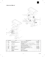
Page 27: ... Rollers Paper guides AR FN3 7 2 8 19 1999 ...

Page 28: ...AR FN3 8 19 1999 7 3 ...

Page 29: ... Gears Others Sensors Belts AR FN3 7 4 8 19 1999 ...

Page 30: ...trouble Check and remedy Check the staple motor operation with SIM 3 3 Trouble code Description Main code Sub code F1 10 Content Staple unit operation trouble Detail Staple operation trouble Cause Motor lock Motor rpm abnormality Motor overcurrent Finisher control PWB trouble Check and remedy Check the staple motor operation with SIM 3 3 11 Content Pusher motor trouble Detail Pusher motor trouble ...

Page 31: ...evator motor rotates normally Off set motor rotates normally Connect connection cable to body properly Check or replace harness or check supply voltage Check or replace harness or check supply voltage Check connections Check harnesses at upper and lower surfaces and harness leading to upper transfer switch for connections and replace if necessary Staple unit moving motor rotates normally Pusher mo...

Page 32: ...pplied to motor connector Check motor and replace if necessary 3 NO YES NO YES YES NO YES NO NO YES NO YES NO YES Is fuse blown out Is load on motor shaft normal Is motor winding shorted Is harness connected normally Motor rotates even slightly Is motor encoder sensor output normal Check main PWB and replace if necessary Replace fuse Check mechanical load and driving system Remove foreign matter R...

Page 33: ...gn matter Replace motor Connect harness properly 5 NO YES Replace main PWB Check sensor mounting and harness and replace if necessary Is sensor mounted properly Is harness connected properly 6 NO YES NO YES NO YES Is each load properly mounted Conduction between coils of each load Conduction between connectors and terminals Replace main PWB Check mounting and replace if necessary Replace clutch or...

Page 34: ... Staple unit HP sensor Jogger motor HP sensor Pusher motor HP sensor EVRE OFHP STHP WR T2PF STND Elevator motor EVM Staple HP sensor Trasport motor encoder PA6 DC brush motor drive circuit H driver IC9 Q1 2 3 4 DC brush motor drive circuit H driver IC12 13 Main drive motor FM Brushless motor FMDIR 2 Phase brushless motor drive circuit IC10 16 20 DC brush motor drive circuit IC1 2 Phase stepping mo...

Page 35: ...B4 TOCXB4 TP13 PB5 DREQ0 TP14 PB6 ADTRG DREQ1 TP15 PB7 RES0 Vss TXD0 P90 TXD1 P91 RXD0 P92 RXD1 P93 IRQ4 SCK0 P94 IRQ5 SCK1 P95 D0 P40 D1 P41 D2 P42 D3 P43 Vss D4 P44 D5 P45 D6 P46 1 2 3 4 5 6 7 8 9 10 11 12 13 14 15 16 17 18 19 20 21 22 23 24 25 A Vcc Vref P70 AN0 P71 AN1 P72 AN2 P73 AN3 P74 AN4 P75 AN5 P76 AN6 DA0 P77 AN7 DA1 A Vss P80 RFSH IRQ0 P81 CS3 RAS IRQ1 P82 CS2 IRQ2 P83 CS1 IRQ3 P84 CS0...

Page 36: ... OUT Data signal D1 29 P32 D2 IN OUT Data signal D2 30 P33 D3 IN OUT Data signal D3 31 P34 D4 IN OUT Data signal D4 32 P35 D5 IN OUT Data signal D5 33 P36 D6 IN OUT Data signal D6 34 P37 D7 IN OUT Data signal D7 35 VCC VCC Power supply 5V 36 P10 A0 OUT Address signal A0 37 P11 A1 OUT Address signal A1 38 P12 A2 OUT Address signal A2 39 P13 A3 OUT Address signal A3 40 P14 A4 OUT Address signal A4 4...

Page 37: ...ect at L 92 VSS GND Power supply GND 93 PA0 STHP IN L Stapler home position signal home position at L 94 PA1 N C 95 PA2 N C 96 PA3 N C 97 PA4 FMPWM OUT L Transport motor control signal PWM output 98 PA5 N C 99 PA6 FMRE IN H Transport motor encoder signal 100 PA7 FMDIR OUT L Transport motor direction control signal CW at L 4 Expansion I O M66500FP A Outline The expansion I O converts data from the ...

Page 38: ...er entry sensor signal On at L 29 VCC VCC Power supply 5V 30 RD RD IN L Data read signal read at L 31 WR WR IN L Data write signal write at L 32 CS CS IN L Chip select signal select at L 33 RESET RESET IN H Reset signal reset at H 34 GND GND Power supply GND 35 A2 A2 IN Address signal A2 36 A1 A1 IN Address signal A1 37 A0 A0 IN Address signal A0 38 D0 D0 IN OUT Data signal D0 39 D1 D1 IN OUT Data...

Page 39: ...to copier is permitted at L F DSR Status display signal line for the signal showing communication request from finisher to copier No communication request from finisher to copier at H Communication request from finisher to copier at L F RES Hard rest signal from copier Reset at H Reset is released at L 74HC14 74HC14 74HC14 74HC14 IC101 IC101 IC101 IC101 5V 5V 5V R125 1 2 R113 4 7K 6 5 10 11 IC101 ...

Page 40: ...gnals also change when the top and front door switch is opened and closed In addition when 24V power supply from the copier is cut off the expansion I O PG0 PWD signal level changes at the above circuit Here are logic s at the time of the power supply from the copier being cut off and the doors opening and closing being detected Upper Lower Status Expansion I O port PG0 PG1 PG2 PG3 Remarks Signal ...

Page 41: ...Here is the driving pattern for the jogger motor PF0 PF1 PF2 PF3 59 60 61 OG1SL 62 OG3SL PC4 PC5 PC6 PC7 49 48 T12CL 47 OG2SL 46 STPDSL PF4 PF5 PF6 PF7 63 64 T3PDSL 1 PDCL 2 STORCL 1 2 3 4 5 6 7 8 13 4 5 12 13 4 5 12 14 11 6 3 14 11 6 3 16 15 14 13 12 11 10 9 I1 I2 I3 I4 I5 I6 I7 GND COM O1 O2 O3 O4 O5 O6 O7 IC14 IC09 IC12 TD62318AP 8 16 9 1 15 10 7 2 I4 I3 I2 I1 O4 O3 O2 O1 VCC2 VCC1 COM2 COM1 GN...

Page 42: ...ischarge motor drive circuit CPU PB0 PB3 IC03 2 5 4 3 PB2 PB1 T30MA T30MA T3M0B T3M0B 3 14 10 6 REFA 5 16 17 REFB RSB IN A IN A IN B IN B IC08 SLA7024MT OUT A OUT A OUT B OUT B GA GB VSA 7 1 8 11 18 4 15 T30MA T30MA T30MB T30MB 24V 12 VSB 2 9 13 TDA TDB RSA R146 47K C139 470P C135 470P 5V C07 47U 35V T30M 24V 24V R141 47K C137 2200P R10 1 1W R142 2 4K R11 1 1W R144 2 4K C138 2200P R143 0 1U C136 6...

Page 43: ...PU is input to the H driver TA7291S IC2 to drive the off set motor which moves the tray sideways against the paper discharge direction in order to sort the sheets discharged to the off set tray tray 3 by the number of sheets specified The rotational direction of the motor is crank controlled in one direc tion CW and braked to a stop at the off set home position To protect the circuit from shorting...

Page 44: ... constant speed As the current flowing into the motor becomes large the current flowing to the R25 also becomes large thus raising the voltage at the negative side of the comparator BA10393F IC15 When this voltage becomes greater than the reference voltage about 1 1V preset at the plus side the output of IC15 becomes at L level thus turning off the IC20 transistor to restrict the current flowing t...

Page 45: ...er unit The stapler unit EH 524S Max Co Ltd staples up to 50 sheets of 80g m2 paper The unit consists of a driving DC motor STM home position sensor STHP non needle sensor LSTS cartridge sensor NCTS and self priming sensor which detects the stapling position of needles READY Item Specification Outside dimensions 97 H 80 W 104 L mm Stapling capacity 52 g m2 sheets 80 g m2 50 sheets below 5 mm thick...

Page 46: ...Y 1 OFM 1 PK 3 5V 3 BL 4 OFHP 2 LB 5 GND2 1 GY FG OFHP OFM CN M 2 24V 2 RD 1 24V2 1 RD CN D 1 24VIN 6 RD 3 GND1 9 GY 5 GND2 8 GY 6 5V 7 BL 11 1 F TXD 1 PL 2 F RXD 2 PK 3 F DTR 3 BR 4 F DSR 4 PK 5 F RES 5 LB 9 GY 10 12 FG CN A CN B DSW1 DSW2 4PIN FM DSW3 T12CL 24V CN K 2 PPSL 2 PL 1 24V 1 RD CN L PPSL Copier Rear 2 2 10 24V 6 RD 9 24V 5 RD 11 RVMA 4 BR 12 RVMA 3 PL 14 RVMB 2 LB 13 RVMB 1 PK 28 OG1S...

Page 47: ...D2 STM STM PL GY BL COM6 GND2 T2PF T2PF LB GY BL COM5 GND2 T1PF T1PF BR GY BL COM4 GND2 PFD4 PFD4 PK GY BL COM3 GND2 PFD3 PFD3 PL GY BL COM2 GND2 PFD2 PFD2 EVM RD EVM LB EVM EVRE GY BL 5V GND2 PK EVRE GY Main PWB 2 2 BL BL PL GY GND2 STID2 5V STID2 RD RD BR BK YE OR BL BL BK BL RD 24V 24V JGMA JGMA JGMB JGMB JGMB RD RD PL BR LB PK JGHP PL GY 5V JGHP BL GND2 GY GY BR BL COM9 STID GND2 STID GY PK CO...

Page 48: ...63 AS 69 P64 RD 70 P65 HWR 71 P66 LWR 72 MD0 73 MD1 74 MD2 75 AVCC 76 VREF 77 P70 AN0 78 P71 AN1 79 P72 AN2 80 P73 AN3 81 P74 AN4 82 P75 AN5 83 P76 AN6 DA0 84 P77 AN7 DA1 85 AVSS 86 P80 RFSH IRQ0 87 P82 CS2 IRQ2 89 P83 CS1 IRQ3 90 P84 CS0P84 91 VSS 92 CS3 RAS IRQ1 88 TEND0 TCLKA 93 TEND1 TCLKB 94 TIOCA0 TCLKC 95 TIOCB0 TCLKD 96 TIOCA1 A23 97 TIOCB1 A22 98 TIOCA2 A21 99 TIOCB2 A20 100 DREQ0 TP14 PB...

Page 49: ... R167 1k R157 2 4k R137 47k R22 2 4k 1 4W R159 47k R20 1 1W R19 1 1W R155 2 4k C156 2200P R135 130 R8 1 1W R9 1 1W R136 2 4k R134 2 4k R132 47k R180 200 IC104B BA10393F 5 6 7 C162 0 1u R163 2 4k R162 680 R128 47k R160 1k R127 47k R13 2 4k 1 4W R149 1k R166 1k R150 200 R147 200 R148 1k R14 2 4k 1 4W R161 1k R168 200 R165 200 R23 2 4k 1 4W R175 1k R153 2 2k R151 1 2k IC101 74HC14 C121 0 1u CNE 09 IC...

Page 50: ...ND2 01 STID2 03 5V T3OD 07 CNJ B16B PHDSS B 5V T3PDHP 05 06 SIGNAL 14 13 T3PDSL 16 N C 15 24V STID STID2 T3OD T3PDHP T3PDSL 24V 24V 03 STSL 08 07 02 04 STMB 09 T3OMA 10 12 11 T3OMA 01 STM STMA STMA CNL B30B PHDSS B SIGNAL NO 24V OG1SL T3OMB STMB 06 05 24V T3OMB 24V 13 14 T3OM INGSL OG1SL OG2SL OG2SL PPSL PPSL OG3SL T12CL GND2 29 30 31 32 24V 24V RRSL T12CL RRSL PSHP1 SPSL N C 17 22 21 16 18 23 24 ...

Page 51: ...3 Main PWB page arrangement 1 2 AR FN3 10 9 8 6 1999 ...

Page 52: ...Main PWB page arrangement 2 2 AR FN3 8 6 1999 10 10 ...

Page 53: ...isesti asennettu Vaihda paristo ainoastaan laitevalmistajan suosittelemaan tyyppiin Hävitä käytetty paristo valmistajan ohjeiden mukaisesti French ATTENTION Il y a danger d explosion s il y a remplacement incorrect de la batterie Remplacer uniquement avec une batterie du même type ou d un type équivalent recommandé par le constructeur Mettre au rebut les batteries usagées conformément aux instruct...

Page 54: ...1186 Japan 1999 August Printed in Japan All rights reserved Printed in Japan No part of this publication may be reproduced stored in a retrieval system or transmitted in any form or by any means electronic mechanical photocopying recording or otherwise without prior written permission of the publisher AR FN3 ...

Reviews: