Sharp aquos PN-L603B, Operation Manual
The Sharp Aquos PN-L603B is an advanced interactive display featuring a sleek design and cutting-edge technology. Enhance your productivity with its high-resolution touchscreen and extensive functionalities. Need assistance operating this device? Look no further! Download the free Operation Manual from manualshive.com to make the most of your Sharp Aquos PN-L603B.
Share
Download


Reviews:
No comments
Related manuals for aquos PN-L603B
IW77
Brand: NEC Pages: 2
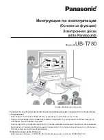
ELITE PANABOARD UB-T780
Brand: Panasonic Pages: 56
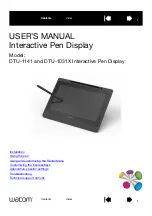
DTU-1141
Brand: Wacom Pages: 61
ElitePANABOARD UB-T880W
Brand: Panasonic Pages: 56
M-115
Brand: Plus Pages: 2

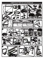
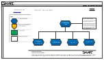
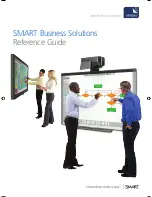
SMART Board 680i3
Brand: Smart Technologies Pages: 6
TT-BOARD PRO Series
Brand: Avtek Pages: 91
IFP6501-V7
Brand: V7 Pages: 38
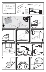
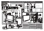
SB680-MP
Brand: SMART Board Pages: 2
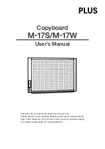
M-17S
Brand: Plus Pages: 28
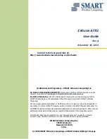
Smart Board 480
Brand: SMART Pages: 2
Inforce 67X1
Brand: SMART Pages: 26
SBX885
Brand: SMART Pages: 25
600i5 series
Brand: Smart Technologies Pages: 4
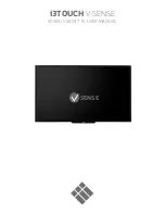
V-SENSE V5503
Brand: i3TOUCH Pages: 22
eBoard
Brand: Ace Pages: 26
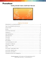
ActivPanel Titanium
Brand: promethean Pages: 62
800ie
Brand: SMART Pages: 32


