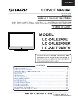
background image


SERVICE MANUAL

Parts marked with "

" are important for maintaining the safety of the set. Be sure to replace these parts with specified ones for maintaining the

safety and performance of the set.

This document has been published to be used for
after sales service only.
The contents are subject to change without notice.

OUTLINE AND LIST OF CHANGED PARTS

OUTLINE.............................................................i
LIST OF CHANGED PARTS 
(LC-32DH77E/RU/S)..........................................ii
LIST OF CHANGED PARTS 
(LC-42DH77E/RU/S)..........................................ii
LIST OF CHANGED PARTS 
(LC-46DH77E/RU/S)..........................................ii

SAFETY PRECAUTION

IMPORTANT SERVICE SAFETY PRE-
CAUTION .......................................................... iii
Precautions for using lead-free solder ..............iv
End of life disposal .............................................v

CHAPTER 1. OPERATION MANUAL

[1] SPECIFICATIONS ......................................... 1-1

CHAPTER 2. REMOVING OF MAJOR PARTS 
(LC-32DH77E/RU/S ONLY)

[1]  REMOVING OF MAJOR PARTS ................... 2-1

CHAPTER 3. ADJUSTMENT PROCEDURE

[1] ADJUSTMENT 

PROCEDURE ....................... 3-1

CHAPTER 4. BLOCK DIAGRAM/WIRING DIAGRAM

[1]  MAIN BLOCK DIAGRAM...............................4-1
[2]  SYSTEM BLOCK DIAGRAM 

(LC-32DH77E/RU/S) .....................................4-2

[3]  SYSTEM BLOCK DIAGRAM 

(LC-42/46DH77E/RU/S) ................................4-3

[4]  OVERALL WIRING DIAGRAM 

(LC-32DH77E/RU/S) .....................................4-4

[5]  OVERALL WIRING DIAGRAM 

(LC-42DH77E/RU/S) .....................................4-5

[6]  OVERALL WIRING DIAGRAM 

(LC-46DH77E/RU/S) .....................................4-6

CHAPTER 5. PRINTED WIRING BOARD

[1]  MAIN UNIT PRINTED WIRING BOARD........5-1

CHAPTER 6. SCHEMATIC DIAGRAM

[1]  DESCRIPTION OF SCHEMATIC DIA-

GRAM............................................................6-1

[2] SCHEMATIC 

DIAGRAM ................................6-2

Parts Guide

TopPage

CONTENTS

CONTENTS

In the interests of user-safety (Required by safety regulations in some countries) the set should be restored to its original condition
and only parts identical to those specified should be used.

OUTLINE

LC

-

32/42/46DH77E/RU/S

This Service Manual covers the differences from LC-32DH77E/RU/S, LC-42/46DH77E/RU/S/V. For other technical information, refer
to the LC-32DH77E/RU/S (No. S19V4LC32D77E) Service Manual and LC-42/46DH77E/RU/S/V (No. S19W3LC42DH77) Service
Manual.
For LED Unit and KEY Unit, refer to the Service Manual for LC-52DH77E/RU/S (No. S49Z2LC52DH77E).
The previous models and the new model can be identified with the following markings.

 The  C  character is added at the end of the model name on the model label.

 The  C  character is also added at the end of the model name on the number label (barcode label) of the packing case. 

 The serial product numbers are 90511112 (LC-32DH77E/RU/S), 90511112 (LC-42DH77E/RU/S), 90611112 (LC-46DH77E/RU/S) 

   and on.

SUPPLEMENT

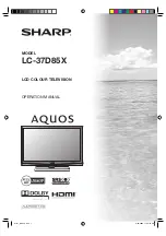
LCD COLOUR TELEVISION

MODELS

LC-32DH77E/RU/S

LC-42DH77E/RU/S

LC-46DH77E/RU/S

No. S59Z5LC32D77C

Summary of Contents for Aquos LC-32DH77E

Page 1: ...GRAM LC 46DH77E RU S 4 6 CHAPTER 5 PRINTED WIRING BOARD 1 MAIN UNIT PRINTED WIRING BOARD 5 1 CHAPTER 6 SCHEMATIC DIAGRAM 1 DESCRIPTION OF SCHEMATIC DIA GRAM 6 1 2 SCHEMATIC DIAGRAM 6 2 Parts Guide TopPage CONTENTS CONTENTS In the interests of user safety Required by safety regulations in some countries the set should be restored to its original condition and only parts identical to those specified...

Page 2: ...tified with the following markings The C character is added at the end of the model name on the model label The C character is also added at the end of the model name on the number label barcode label of the packing case The serial product numbers are 90511112 LC 32DH77E RU S 90511112 LC 42DH77E RU S 90611112 LC 46DH77E RU S and on 142 JAPAN JAPAN B LC 32DH77E LC 42DH77E LC 46DH77E POLAND C C C Ad...

Page 3: ...TKE266FM17 Changed refer to the LC 52DH77E RU S POWER Unit Unit Replacement Item RDENCA322WJQZ No Changed INVERTER Unit Unit Replacement Item RUNTKA534WJZZ No Changed Tuner unit RTUDAA019WJQZ No Changed LCD PANEL 42 LCD Panel Module R1LK420D3LW80Y No Changed CABINET AND MECHANICAL PARTS Please refer to a parts list LCD PANEL MODULE Assembly Please refer to a parts list Ref No DESCRIPTION LC 46DH77...

Page 4: ... the AC voltage drop across the resistor All checks must be repeated with the AC cord plug connection reversed If necessary a nonpolarized adaptor plug must be used only for the purpose of completing these checks Any reading of 1 05 V peak this corresponds to 0 7 mA peak AC or more is excessive and indicates a potential shock hazard which must be corrected before returning the monitor to the owner...

Page 5: ...onal lead solder by 40 C and as it has poor solder wettability you may be apt to keep the soldering bit in contact with the PWB for extended period of time However Since the land may be peeled off or the maximum heat resistance temperature of parts may be exceeded remove the bit from the PWB as soon as you confirm the steady soldering condition Lead free solder contains more tin and the end of the...

Page 6: ...returned free of charge to the dealer even if you don t purchase a new product Further collection facilities are listed on the homepage of www swico ch or www sens ch B Information on Disposal for Business Users 1 In the European Union If the product is used for business purposes and you want to discard it Please contact your SHARP dealer who will inform you about the take back of the product You ...

Page 7: ...utput C I Common Interface EN50221 R206001 OUTPUT RCA pin AUDIO R L Headphones Ø 3 5 mm jack Audio output OSD language Czech Danish Dutch English Estonian Finnish French German Greek Hungarian Italian Latvian Lithuanian Norwegian Polish Portuguese Russian Slovak Slovene Spanish Swedish Turkish Ukrainian Power Requirement AC 220 240 V 50 Hz Power Consumption Method IEC62087 210 W 0 3 W Standby 220 ...

Page 8: ...ht Chassis Ass y Lamp Holder L Lamp holder R and Lamps 4 Remove the 4 lock screws and detach the GND PWBs 5 Detach the 2 CS FPCs and 4 Ferrite Cores 6 Remove the 6 lock screws and detach the LCD Control PWB 1 2 3 4 Panel Chassis Ass y Bottom Panel Chassis Ass y Top Back Light Chassis Ass y LCD Control PWB GND PWB CS FPC Ferrite Core Ferrite Core GND PWB 3 Bezel Ass y 1 2 Lens Sheet Diffusion Sheet...

Page 9: ...s achieved in Step 4 press the OK key to turn the pattern to OFF 2 Entering and exiting the adjustment process mode 1 Unplug the AC power cord of running TV set to force off the power 2 While holding down the VOL and INPUT keys on the set at once plug in the AC power cord to turn on the power The letter K appears on the screen 3 Next hold down the VOL and P keys on the set at once Multiple lines o...

Page 10: ... name MODEL NAME 6 Item name Max 30 char 7 Parameter Max 60 char 1 Present page number of total pages 4 Inducing display 3 Present colour system 2 Input that has been selected now 5 Model name 1 16 INPUT1 AUTO EURO 32E_DH77E MAIN Version 1 00 E 2008 1HDE2 BOOT Version Monitor Version 1 0 T CON H 264Version CPLD Version c3 EQ DATA CHECKSUM ROM LAMP ERROR 0 MONITOR ERR CAUSE 11 11 11 11 NORMAL STAND...

Page 11: ...VIC READ OFF Picture level acquisition function Level appears in green on the upper right 3 16 TUNER ADJ 1 RF AGC ADJ Enter RF AGC auto adjustment execution 2 TUNER ADJ Enter TUNER auto adjustment execution 3 PAL TUNER ADJ Enter PAL TUNER auto adjustment execution 4 RF AGC ADJ CA 8CH Enter RF AGC auto adjustment execution CA 8CH 5 TUNER ADJ CA 8CH Enter TUNER auto adjustment execution CA 8CH 6 PAL...

Page 12: ...TOFF 64 SCART B CUTOFF adjustment value 5 SCART R GAIN 44 SCART R GAIN adjustment value 6 SCART G GAIN 44 SCART G GAIN adjustment value 7 SCART B GAIN 44 SCART B GAIN adjustment value 10 16 LUMAADJ 1 VCOM ADJ 0 Common bias adjustment 2 LCD LUMA ADJ Enter Upper and lower brightness difference adjustment 3 LCD LUMA UP 0 4 LCD LUMA DOWN 0 11 16 FR DDRTEST 1 DDRA TEST1 Enter Execute DDRA test 1 2 DDRA...

Page 13: ...s to EEPROM 2 EEP RECOVER OFF Reading setting values from EEPROM 3 MONITOR ERROR CAUSE RESET OFF Reset of monitor error cause 4 STANDBY CAUSE RESET OFF Reset stand by cause 5 MODEL NAME DH77 Model name setting 6 PANEL SIZE 32 42 46 Panel size setting 32 37 42 46 52 65 7 PRODUCT EEP ADR 0x 0 Don t touch when serving for producer of factory 8 PRODUCT EEP DATA 0x 0 Don t touch when serving for produc...

Page 14: ...If the above phenomenon 1 occurs 5 times consecutively it becomes impossible to turn on the power The power LED remained red 2 Measures 1 Checking with lamp error detection OFF Enter the adjustment process mode referring to 2 Entering and exiting the adjustment process mode If there is a problem with the lamp or lamp circuit the lamp will go out The power LED is green Then you can check the operat...

Page 15: ...utting three digits If the Pass Word is it shifts to the PUBLIC Mode setting screen In another case the screen is erased and it operates in the ordinary mode 2 Exiting the Public Mode screen There are two following ways to exit the Public Mode setting screen 1 Turn off the power 2 Select Execution in the PUBLIC_Mode to execute it Activate the restart under the set content Here the START input SOUR...

Page 16: ...ected item Decision ok Execution Used by the items Execution and RESET PUBLIC Mode R C Ordinary operation mode It enters the PUBLIC Mode PUBLIC MODE Flag is set to ON PUBLIC Mode It exits the PUBLIC Mode PUBLIC MODE Flag does not change Any set item in PUBLIC Mode is not initialized Public Mode POWER ON FIXED VARIABLE SHUT DOWN MODE NORMAL MAXIMUM VOLUME 60 VOLUME FIXED VARIABLE VOLUME FIXED LEVEL...

Page 17: ...Default NORMAL Function Scanning or recording of the digital tuner is enabled disabled when turning off the power It is possible to put into the standby state instantaneously due to power off input Remarks When selecting QUICK the function does not work for the following items The possibleme thod differs from model to model deleting the item selection impossible etc ON TIMER QUICK START DIGITAL FI...

Page 18: ... the process mode inspection mode or hotel mode is enabled regardless of this setting All the keys are enabled regardless of this setting while entering the process mode inspection mode or hotel mode For the main unit s MENU key menu operation is possible regardless of the setting during the initial setting when the power is turned on for the first time Option RESPOND or NO RESPOND loop enabled De...

Page 19: ...rohibited When set to NORMAL START MODE FIXED is set to VARIABLE and selection is prohibited Option VARIABLE FIXED AC CTRL or AC RC CTRL loop enabled Default VARIABLE Function When set to FIXED switching to another channel or input is impossible after start up in the set value of INPUT MODE START When set to AC CTRL the unit starts in the set value of INPUT MODE START in the case of the ACON only ...

Page 20: ... menu are enabled or disabled The same item as HOTELMODE in the adjustment process menu Remarks Each operation of the hotel mode is impossible unless this item is set to ON Composite signal PAL SECAM 0 7Vp p 0 02Vp p Pedestal to white level RGB signal 0 7Vp p 0 02Vp p 15K component signal 50 Hz Y level 0 7Vp p 0 02Vp p Pedestal to white level PB PR level 0 7Vp p 0 02Vp p 33K component signal Y lev...

Page 21: ... SECAM full field colour bar Terminal EXT1 SCART video input Send the SECAM full field colour bar colour saturation 75 signal to the SCART video input of EXT1 2 Auto adjustment performance Process page No 4 16 Point the cursor to SECAM ADJ and press the OK key The adjustment is complete when SECAM ADJ OK is displayed Adjustment point Adjustment Conditions Adjustment procedure 1 Setting Signal COMP...

Page 22: ...edure 1 Setting Signal XGA 60Hz 100 full field color bar Terminal EXT4 PC input Send the XGA 60Hz 100 full field color bar color saturation 100 signal to the PC input of EXT4 2 Auto adjustment performance Process page No 8 16 Point the cursor to ANALOG PC ADJ and press the OK key The adjustment is complete when ANALOG PC ADJ OK is displayed Adjustment point Adjustment Conditions Adjustment procedu...

Page 23: ...e 2176 x G value of point 6 3712 fractions rounded off and adjust the RB so that it becomes the standard value 5 Set the point 3 to the specified gradation set the G correction value 1824 x G value of point 6 3712 fractions rounded off and adjust the RB so that it becomes the standard value 6 Set the point 2 to the specified gradation set the G correction value 1248 x G value of point 6 3712 fract...

Page 24: ...dure the NG marking turns red NOTE In such case try to upgrade the software again If it still fails the hardware may be in trouble Adjustment point Adjustment conditions Adjustment procedure 1 Factory setting Complete the setting by turning off the AC power In INDUSTRY INIT of the process page No 2 16 select the destination EUROPE RUS SIA SWEDEN using the R C Volume keys and press the R C OK key i...

Page 25: ...ly is turned off 8 Now the software has been upgraded NOTE Then get the set started and call the process adjustment screen 1 16 to check the main software version CAUTION 1 Do not take out and put in the USB flash memory during formatting 2 It takes about one minute to the rewriting completion Please confirm the upgrade status on the screen becomes 100 3 The AC power supply of the set is waited fo...

Page 26: ...LC 32 42 46DH77E RU S 3 18 M E M O ...

Page 27: ...CEC_0 4 BRT 34 4 4 POWG_LED FB PS_ON VIN 8 KEY1 61 VSS 12 62 59 7 1 STB 2 EN XCOUT LED_R AMP13 5V COMP D9613 OPC 3 3V D_POW R9612 LED_OPC 11 2 IR_RECEVER D103 SRESET CNVSS ERR_PNL 9633 Q104 VSS 8 5 COMP SMPOWHOLD 2 6 PM_REQ POW13V TL9632 BST ANT 5V_SW R C R9621 12 L9604 BU3 3V CBOOT 23 OPC 3 3V TXD_CPU 2 VDD 1 3 4 6 7 GND ERR 13 D2003 LED_5V R9632 D_POW 2 IRPASS C9612 C9645 98 C2002 R115 9 VCC1 14...

Page 28: ...SCL 400Hz SC1_IN_L R OPC 3 3V etc BR24C21F CVBS_IN_L R BU 5V TEST_MODE SLOWSW2 N_RESET IC3301 SC2_CVBS_Y SPK_OUT S24C508J CPU_UATXD2_UCOM X4401 SC502 OPT_OUT SC2_CVBS Y USB_DP N DDC_3 SC2_IN_L R SC501 CVBS__IN VOL UP DDC_2 Disclete RS_BUF_CNT D1 05V COMMON SIF STB Disclete HP_PLUG Spliter HDMI 2 Disclete SC4401 GPFSV51V SC1_Y C HDMI 3 HV_MODE CI_DATA ANALOG_RGB S2002 TUNER_SDA SCL EXE_LED DET_POW3...

Page 29: ..._L R I2C1_SDA OPC 3 3V CPU1 2V LR_OUT MINI_PLUG SC1_CVBS Y TUNER_SDA SCL IC2009 HDMI 1 SIF KEY2 CEC_I12 UR 13 5V TC7SH00U OPC DET_SYNC SPK_OUT FS P2001 TUNER_OUT_L R SC2_Y C DET_COND COMP_YPbPr R CEC_O12 Connector S80927NM TS_CI_IN J505 SW LED_R SC2_Y C VCOM_WP Debug AC_DET EEPROM HP SLOWSW2 LED_OPC SC503 CVBS BYPASS DET_POW2_PNL12V HP_L R BR24C21F DET_COND IC503 CVBS_YU_OUT AV_LINK TMDS_Rx I2C_SI...

Page 30: ...4 EXT6 HDMI2 PD LB POWER INVERTER_UNIT DUNTKF096WE P7002 P7003 SC4801 SPEAKER_UNIT L SPEAKER_UNIT R RA SP KM EXT7 HDMI3 EXT8 CVBS AUDIO_OUT T7501 T7502 CN7503 CN7504 CN7505 CN7506 T7503 CN7507 CN7508 T7504 CN7509 CN7510 T7505 CN7511 T7506 CN7512 CN7513 CN7514 T7507 CN7515 CN7516 1 P102 15 SC503 P9601 SC502 J3301 SC1502 J504 P2601 9 IC3302 SC1801 J505 SC504 D520 1 1 15 P2603 1 SC1503 1 IC3502 12 1 ...

Page 31: ... SC502 J506 D520 IC3502 1 2 P3301 J505 IC3501 19 P2002 20 J3301 4 1 SC1502 4 P2001 J504 1 P9601 14 P9602 1 J502 IC4405 SC4401 R C LED_UNIT QCNW H854WJQZ QCNW H857WJQZ QCNW H856WJQZ QCNW H848WJQZ QCNW J551WJQZ RUNTKA534WJZZ INVERTER_UNIT LB LA QCNW H858WJQZ QCNW H852WJQZ QCNW H853WJQZ KEY_UNIT QCNW H951WJQZ QCNW H950WJQZ KM DUNTKE266WE LCD_CONTROL_UNIT P7003 SC4801 P7002 DUNTKF096WE LB LA PL LB1 PD...

Page 32: ...T7501B T7502B T7503B T7504B T7505B 15 41 1 4 1 1 SC1801 P2603 P2003 SC8452 12 IC3302 SC503 J503 SC501 1 10 P2602 2 SC504 J501 1 4 1 1 IC2002 SC1503 IC1504 15 SC1802 1 9 1 1 P2701 P2601 20 19 SC502 J506 D520 IC3502 1 2 P3301 J505 IC3501 19 P2002 20 J3301 4 1 SC1502 4 P2001 J504 1 P9601 14 P9602 1 J502 SC4401 IC4405 R C LED_UNIT SPEAKER_CONNECTOR QCNW H339WJQZ QCNW H755WJQZ QCNW H753WJQZ QCNW H956WJ...

Page 33: ...LC 32 42 46DH77E RU S 5 1 LC 32DH77E Service Manual CHAPTER 5 PRINTED WIRING BOARD 1 MAIN UNIT PRINTED WIRING BOARD 1 23 10 9 7 6 5 4 8 J A B C D E F G H I 13 11 19 18 16 15 14 12 17 MAIN Unit Side A ...

Page 34: ...02 FB502 FB503 FB504 FB505 FB506 FB507 R3510 FB508 R3511 FB509 R3512 R3321 R3322 R3323 FB510 R501 FB511 R502 R3326 FB512 R503 FB513 FB514 R504 R505 FB515 R506 FB1102 FB516 R507 FB517 R508 FB518 FB519 R509 R3330 R3331 R510 FB520 FB521 R511 R512 FB522 FB523 R513 FB524 R3338 R514 FB525 R515 R3339 FB526 R516 FB527 R517 FB528 R518 R519 FB529 P2001 P2002 R3342 P2003 R520 FB530 X4401 R521 R3345 FB531 R33...

Page 35: ...LC 32 42 46DH77E RU S 5 3 1 2 3 10 9 7 6 5 4 8 J A B C D E F G H I 13 11 19 18 16 15 14 12 17 MAIN Unit Side B ...

Page 36: ...556 R4437 R1557 R4438 R9640 R9641 R9642 R9643 R9644 R9645 R9646 R9647 R1560 R9648 R4441 R9649 R1564 R4445 R4446 R4447 R9650 R9651 D2701 R9652 R2702 D2707 R2703 R2704 R2705 R4453 R2707 R4454 R1574 R4455 R2709 R1575 R4456 R1576 R4457 R1577 R1578 Q501 R1579 Q502 Q503 Q504 R2711 R4460 R1580 R1581 R4462 R4463 R4464 R4465 R2719 R9670 R9671 R9672 R9673 R2726 C3308 R9681 R9682 R9683 R9684 C3504 C3310 C331...

Page 37: ...stors are 5 unless otherwise noted K 10 F 1 D 0 5 3 All resistors are 1 16W unless otherwise noted CAPACITOR 1 All capacitors are µF unless otherwise noted P pF µµF 2 All capacitors are 50V unless otherwise noted CAUTION This circuit diagram is original one therefore there may be a slight difference from yours SAFETY NOTES 1 DISCONNECT THE AC PLUG FROM THE AC OUTLET BEFORE REPLACING PARTS 2 SEMICO...

Page 38: ...LC 32 42 46DH77E RU S 6 2 2 SCHEMATIC DIAGRAM 1 2 3 10 9 7 6 5 4 8 J A B C D E F G H I 13 11 19 18 16 15 14 12 17 MAIN Unit 1 AND SHADED COMPONENTS SAFETY RELATED PARTS ...

Page 39: ...LC 32 42 46DH77E RU S 6 3 1 2 3 10 9 7 6 5 4 8 J A B C D E F G H I 13 11 19 18 16 15 14 12 17 MAIN Unit 2 ...

Page 40: ...LC 32 42 46DH77E RU S 6 4 1 2 3 10 9 7 6 5 4 8 J A B C D E F G H I 13 11 19 18 16 15 14 12 17 MAIN Unit 3 ...

Page 41: ...LC 32 42 46DH77E RU S 6 5 1 2 3 10 9 7 6 5 4 8 J A B C D E F G H I 13 11 19 18 16 15 14 12 17 MAIN Unit 4 ...

Page 42: ...LC 32 42 46DH77E RU S 6 6 1 2 3 10 9 7 6 5 4 8 J A B C D E F G H I 13 11 19 18 16 15 14 12 17 MAIN Unit 5 ...

Page 43: ...LC 32 42 46DH77E RU S 6 7 1 2 3 10 9 7 6 5 4 8 J A B C D E F G H I 13 11 19 18 16 15 14 12 17 MAIN Unit 6 ...

Page 44: ...LC 32 42 46DH77E RU S 6 8 1 2 3 10 9 7 6 5 4 8 J A B C D E F G H I 13 11 19 18 16 15 14 12 17 MAIN Unit 7 ...

Page 45: ...LC 32 42 46DH77E RU S 6 9 1 2 3 10 9 7 6 5 4 8 J A B C D E F G H I 13 11 19 18 16 15 14 12 17 MAIN Unit 8 ...

Page 46: ...LC 32 42 46DH77E RU S 6 10 1 2 3 10 9 7 6 5 4 8 J A B C D E F G H I 13 11 19 18 16 15 14 12 17 MAIN Unit 9 ...

Page 47: ...LC 32 42 46DH77E RU S 6 11 1 2 3 10 9 7 6 5 4 8 J A B C D E F G H I 13 11 19 18 16 15 14 12 17 MAIN Unit 10 ...

Page 48: ...LC 32 42 46DH77E RU S 6 12 1 2 3 10 9 7 6 5 4 8 J A B C D E F G H I 13 11 19 18 16 15 14 12 17 MAIN Unit 11 ...

Page 49: ... PartsGuide 1 PRINTED WIRING BOARD ASSEMBLIES LC 32DH77E RU S 2 PRINTED WIRING BOARD ASSEMBLIES LC 42DH77E RU S 3 PRINTED WIRING BOARD ASSEMBLIES LC 46DH77E RU S 4 LCD PANEL 5 DUNTKF190FM01 MAIN Unit 6 CABINET PARTS LC 32DH77E RU S 7 LCD PANEL MODULE ASSEMBLY LC 32DH77E RU S 8 CABINET PARTS LC 42DH77E RU S 9 LCD PANEL MODULE ASSEMBLY LC 42DH77E RU S 10 CABINET PARTS LC 46DH77E RU S 11 LCD PANEL MO...

Page 50: ...amic C529 VCKYCZ1HB102KY AB J Capacitor 1000p 50V Ceramic C530 VCKYCZ1HB471KY AB J Capacitor 470p 50V Ceramic C531 VCKYCZ1HB471KY AB J Capacitor 470p 50V Ceramic C532 VCCCCZ1HH101JY AB J Capacitor 100p 50V Ceramic C533 VCCCCZ1HH101JY AB J Capacitor 100p 50V Ceramic C534 RC KZA510WJPZY AB J Capacitor 10 16V Ceramic C535 RC KZA510WJPZY AB J Capacitor 10 16V Ceramic C536 VCKYCZ1HB471KY AB J Capacitor...

Page 51: ...B104KY AB J Capacitor 0 1 10V Ceramic C1517 VCKYCZ1HB102KY AB J Capacitor 1000p 50V Ceramic C1518 VCKYCZ1HB102KY AB J Capacitor 1000p 50V Ceramic C1519 RC KZA520WJQZY AA J Capacitor 10 10V Ceramic C1520 RC KZA520WJQZY AA J Capacitor 10 10V Ceramic C1522 RC KZA616WJQZY AB J Capacitor 10 10V Ceramic C1523 RC KZA616WJQZY AB J Capacitor 10 10V Ceramic C1531 RC KZA520WJQZY AA J Capacitor 10 10V Ceramic...

Page 52: ...WJQZY AB J Capacitor 10 10V Ceramic C3352 VCKYCZ1AB104KY AB J Capacitor 0 1 10V Ceramic C3353 VCKYCZ1AB104KY AB J Capacitor 0 1 10V Ceramic C3355 RC KZA616WJQZY AB J Capacitor 10 10V Ceramic C3356 VCKYCZ1AB104KY AB J Capacitor 0 1 10V Ceramic C3357 VCKYCZ1AB104KY AB J Capacitor 0 1 10V Ceramic C3358 VCKYCZ1EF104ZY AA J Capacitor 0 1 25V Ceramic C3359 VCKYCZ1EB103KY AA J Capacitor 0 01 25V Ceramic ...

Page 53: ...c C4412 VCKYCZ1EF104ZY AA J Capacitor 0 1 25V Ceramic C4413 RC KZA510WJPZY AB J Capacitor 10 16V Ceramic C4414 VCAAPD1AJ686MY AE J Capacitor 68 10V Electrolytic C4415 RC KZA510WJPZY AB J Capacitor 10 16V Ceramic C4416 VCKYCZ1EF104ZY AA J Capacitor 0 1 25V Ceramic C4417 VCKYCZ1EF104ZY AA J Capacitor 0 1 25V Ceramic C4418 RC KZA510WJPZY AB J Capacitor 10 16V Ceramic C4419 VCKYCZ1EF104ZY AA J Capacit...

Page 54: ...0V Ceramic C9663 VCCCCZ1HH101JY AB J Capacitor 100p 50V Ceramic C9666 VCKYCZ1EB103KY AA J Capacitor 0 01 25V Ceramic D504 RH EXA512WJZZY AB J Diode MAZ8039GHL D505 RH EXA554WJZZY AB J Diode MAZ8150GML D507 RH EXA523WJZZY AB J Diode MAZ8056GML D508 RH EXA523WJZZY AB J Diode MAZ8056GML D509 RH EXA523WJZZY AB J Diode MAZ8056GML D510 RH EXA523WJZZY AB J Diode MAZ8056GML D512 VHDKDS184 1Y AB J Diode KD...

Page 55: ...rrite Bead FB507 RBLN 0061TAZZY AD J Ferrite Bead FB508 RBLN 0077TAZZY AB J Ferrite Bead FB510 RBLN 0077TAZZY AB J Ferrite Bead FB511 RBLN 0077TAZZY AB J Ferrite Bead FB512 RBLN 0077TAZZY AB J Ferrite Bead FB513 RBLN 0077TAZZY AB J Ferrite Bead FB514 RBLN 0077TAZZY AB J Ferrite Bead FB515 RBLN 0077TAZZY AB J Ferrite Bead FB516 RBLN 0077TAZZY AB J Ferrite Bead FB517 RBLN 0077TAZZY AB J Ferrite Bead...

Page 56: ...IC 74AHC1G08GW G 125 IC2008 VHi7WH126FU 1Y AE J IC TC7WH126FU TE12L F IC2009 VHiTC7SH00U 1Y AC J IC TC7SH00FU T5L JF T IC2601 VHiHC2G66DP 1Y AD J IC 74HC2G66DP 125 IC2701 VHiYDA148QZ 1Y AL J IC YDA148 QZE2 IC3301 VHiBD6538G 1Y AD J IC BD6538G TR IC3302 RH iXC773WJQZQ N J IC MT5391UHMJ IC3501 RH iXC790WJQZQ N J IC K4T1G164QE HCF8 IC3502 RH iXC790WJQZQ N J IC K4T1G164QE HCF8 IC4404 VHiAOZ1320C 1Y AE...

Page 57: ... 1Y AA J Transistor LTC144EEBFS8TL Q9609 VSLTA124EEB 1Y AA J Transistor LTA124EEBFS8TL Q9610 VSRSS050P03 1Y AG J Transistor RSS050P03TB R504 VRS CZ1JF103FY AB J Resistor 10k 1 16W Metal Oxide R505 VRS TQ2EF750JY AA J Resistor 75 1 4W Metal Oxide R506 VRS TQ2EF750JY AA J Resistor 75 1 4W Metal Oxide R507 VRS TQ2EF750JY AA J Resistor 75 1 4W Metal Oxide R508 VRS CZ1JF333FY AA J Resistor 33k 1 16W Me...

Page 58: ...ide R604 VRS CZ1JF103JY AA J Resistor 10k 1 16W Metal Oxide R605 VRS CZ1JF104JY AA J Resistor 100k 1 16W Metal Oxide R606 VRS TW2ED101JY AA J Resistor 100 1 4W Metal Oxide R607 VRS TW2ED101JY AA J Resistor 100 1 4W Metal Oxide R608 VRS TV1JD101JY AA J Resistor 100 1 10W Metal Oxide R609 VRS TV1JD101JY AA J Resistor 100 1 10W Metal Oxide R610 VRS CZ1JF104JY AA J Resistor 100k 1 16W Metal Oxide R611...

Page 59: ...Oxide R2004 VRS CZ1JF103JY AA J Resistor 10k 1 16W Metal Oxide R2005 VRS CZ1JF100JY AA J Resistor 10 1 16W Metal Oxide R2007 VRS CZ1JF472JY AA J Resistor 4 7k 1 16W Metal Oxide R2008 VRS CZ1JF102JY AA J Resistor 1k 1 16W Metal Oxide R2009 VRS CZ1JF102JY AA J Resistor 1k 1 16W Metal Oxide R2010 VRS CZ1JF333JY AA J Resistor 33k 1 16W Metal Oxide R2011 VRS CZ1JF472JY AA J Resistor 4 7k 1 16W Metal Ox...

Page 60: ...CZ1JF000JY AA J Resistor 0 1 16W Metal Oxide R2639 VRS CZ1JF104JY AA J Resistor 100k 1 16W Metal Oxide R2701 VRS CZ1JF000JY AA J Resistor 0 1 16W Metal Oxide R2712 VRS CZ1JF274FY AA J Resistor 270k 1 16W Metal Oxide R2713 VRS CZ1JF104FY AB J Resistor 100k 1 16W Metal Oxide R2714 VRS CZ1JF000JY AA J Resistor 0 1 16W Metal Oxide R2715 VRS CZ1JF474JY AA J Resistor 470k 1 16W Metal Oxide R2717 VRS CZ1...

Page 61: ...FF100JY AA J Resistor 10 1 32W Metal Composition R3505 VRK SB1FF100JY AA J Resistor 10 1 32W Metal Composition R3506 VRK SB1FF100JY AA J Resistor 10 1 32W Metal Composition R3507 VRK SB1FF100JY AA J Resistor 10 1 32W Metal Composition R3508 VRK SB1FF100JY AA J Resistor 10 1 32W Metal Composition R3509 VRS CZ1JF102FY AA J Resistor 1k 1 16W Metal Oxide R3510 VRS CZ1JF102FY AA J Resistor 1k 1 16W Met...

Page 62: ...CZ1JF000JY AA J Resistor 0 1 16W Metal Oxide R8477 VRS CZ1JF472JY AA J Resistor 4 7k 1 16W Metal Oxide R8478 VRS CZ1JF472JY AA J Resistor 4 7k 1 16W Metal Oxide R8479 VRS CZ1JF473JY AA J Resistor 47k 1 16W Metal Oxide R8480 VRK SA1JF100JY AB J Resistor 10 1 16W Metal Composition R8481 VRS CZ1JF332JY AA J Resistor 3 3k 1 16W Metal Oxide R8482 VRS CZ1JF472JY AA J Resistor 4 7k 1 16W Metal Oxide R932...

Page 63: ... SC502 QSOCZA161WJZZ AG J Socket SC503 QSOCZA161WJZZ AG J Socket SC504 QSOCNA715WJZZ AL J Socket SC1501 QSOCZA072WJZZQ AH J Socket SC1502 QSOCZA171WJZZY AF J Socket SC1503 QSOCZA171WJZZY AF J Socket TH2001 VHHM1103J03 1Y AC J Thermistor TU1101 RTUDAA019WJQZ AZ J Tuner VA501 RH VXA005WJZZY AA J Varistor AVR M1005C270MTABBG VA502 RH VXA005WJZZY AA J Varistor AVR M1005C270MTABBG VA503 RH VXA005WJZZY ...

Page 64: ...S 35 40 2 36 2 1 2 4 2 3 2 3 2 4 2 3 2 4 2 3 2 4 2 2 3 3 1 3 3 3 2 34 39 24 23 27 26 29 22 38 20 15 34 38 15 33 16 38 4 9 37 38 12 13 6 11 38 7 38 18 38 38 8 8 10 19 38 37 37 38 38 17 38 38 14 38 21 1 3 2 1 5 1 4 1 3 1 1 5 1 2 1 3 1 2 1 41 1 1 1 30 25 31 28 ...

Page 65: ...0 LHLDWA143WJKZ AC J Wire Holder Cable 11 LHLDFA062WJKZ J Wire Holder Power PWB 12 LHLDZB300WJ1A AF P LCD Holder A 13 LHLDZB301WJ1A AF P LCD Holder B 14 LX WZA053WJZZ AN P Washer Power 15 NSFTZA237WJFN AC J Screw x4 D Sub 16 PSLDMB475WJFW AN P Full Shield 17 PSLDMB516WJN0 AH P T CON Shield 18 PSPAZB313WJKZ AC J Spacer TCON 19 PSPAZB864WJKZ AG J Spacer 20 PSPAZC237WJKZ AH N P Cooling Sheet x2 21 PS...

Page 66: ...LC 32 42 46DH77E RU S 18 7 LCD PANEL MODULE ASSEMBLY LC 32DH77E RU S 7 8 9 10 13 5 1 6 14 15 11 12 22 21 17 16 18 19 20 24 24 25 24 4 3 4 2 23 23 23 23 23 23 23 23 26 27 27 27 26 26 26 28 ...

Page 67: ... Lamp Holder R 12 RLMP 0663TPZZ AS J Lamp Unit x14 13 QSOCFA003WJZZ AD J Lamp Socket x14 14 RUNTK3839TPZZ AM J GND PWB 15 RUNTK3840TPZZ AM J GND PWB 16 Not Available Back Light Chassis Ass y 17 PCOVWA053WJKZ J SJ Connector Cover Top 18 PCOVWA054WJKZ J SJ Connector Cover Bottom 19 CPWBX4151TPXF J LCD Control PWB Unit 20 QPWBM0792TPZZ AL J CS FPC 21 QPWBM0793TPZZ AL J CS FPC 22 RCORFA061WJZZ AG J Fe...

Page 68: ... RU S 2 2 1 38 34 38 11 35 39 13 2 2 4 3 4 1 4 2 4 2 4 3 5 3 5 2 5 2 4 1 10 9 4 8 9 5 3 5 1 5 1 36 36 1 1 2 2 1 3 1 4 1 2 3 1 2 1 7 25 40 5 37 37 37 37 1 1 1 2 16 3 1 3 4 5 3 2 29 30 37 15 26 24 22 21 20 18 6 1 6 2 6 14 33 12 32 37 37 12 33 37 19 17 23 ...

Page 69: ...Label 7 GCOVAD248WJ1A AK P Bottom Cover 8 LHLDWA048WJKZ AB J Wire Holder x2 SP_L 9 LHLDWA143WJKZ AC J Wire Holder x2 CABLE 10 LHLDZA934WJKZ AB J Power PWB Holder x5 11 LX BZA170WJF9 AC P Screw x2 Vesa Boss 12 NSFTZA237WJFN AC J Shaft x4 D SUB 13 PSHEPA543WJZZ AA N P Sheet For Vesa x2 14 PSLDMB539WJFW AP N P Full Shield 15 PSPAZC237WJKZ AH N P Cooling Sheet x2 16 QCNW H951WJQZ AF N P Connecting Cor...

Page 70: ...LC 32 42 46DH77E RU S 22 9 LCD PANEL MODULE ASSEMBLY LC 42DH77E RU S 7 6 1 4 23 16 15 17 25 28 18 22 25 21 24 20 24 3 14 29 30 2 10 9 26 5 8 19 27 11 13 12 13 ...

Page 71: ...1 J Sheet Holder Unit x2 14 CSLDMB528WJ01 J LCD Control Unit Cover 15 PCOVWA036WJKZ AM J Cover 16 PCOVWA037WJKZ AL J Cover 17 RUNTKA534WJZZ BP J INVERTER Unit 18 RUNTKA536WJZZ AP J GND PWB 19 RUNTKA537WJZZ AP J GND PWB 20 QPWBM0567TPZZ AG J SC FPC 21 QPWBM0570TPZZ AG J SC FPC 22 CPWBX4023TPXE BW J LCD Control Unit 23 PSHEP2941TPZZ J Heat Radiation Sheet for LCD Control unit 24 RCORFA061WJZZ AG J F...

Page 72: ...77E RU S 2 2 1 35 39 10 36 40 12 2 2 38 18 16 22 23 21 20 19 17 38 25 14 13 34 38 33 11 11 38 6 1 38 6 2 34 6 37 37 9 8 4 1 4 2 4 2 4 1 5 3 5 2 5 1 5 2 5 1 1 2 3 1 2 1 1 2 2 1 2 1 4 1 1 1 3 1 7 24 30 31 15 3 1 3 3 2 41 4 3 38 4 3 38 38 5 3 38 4 5 4 5 ...

Page 73: ...AV Cover 6 2 HINDPD186WJSA AD S Side AV Label 7 GCOVAD248WJ1A AP N S Bottom Cover 8 LHLDWA133WJKZ AC J Wire Holder CABLE 9 LHLDZA934WJKZ AB J Power PWB Holder x3 10 LX BZA170WJF9 AB S Screw x2 CAB B 11 NSFTZA237WJFN AC J Shaft x4 D SUB 12 PSHEPA543WJZZ AA S Diffusion Sheet x2 13 PSLDMB539WJFW AQ N S Full Shield 14 PSPAZC237WJKZ AH N S Cooling Sheet x2 15 QCNW H324WJQZ AF S Connecting Cord KM 16 QC...

Page 74: ...LC 32 42 46DH77E RU S 26 11 LCD PANEL MODULE ASSEMBLY LC 46DH77E RU S 2 13 13 9 7 6 5 8 10 11 12 27 28 28 27 1 29 4 26 23 26 30 14 31 15 3 17 18 16 4 21 24 22 25 25 4 4 19 20 ...

Page 75: ...er Unit x2 14 CSLDMB528WJ01 J LCD Control Unit Cover 15 PCOVWA038WJKZ AM J Cover 16 PCOVWA039WJKZ AM J Cover 17 RUNTKA538WJZZ BF J INVERTER Unit 18 RUNTKA539WJZZ BF J INVERTER Unit 19 RUNTKA540WJZZ AP J GND PWB 20 RUNTKA541WJZZ AP J GND PWB 21 QPWBM0782TPZZ AG J FPC 22 QPWBM0783TPZZ AG J FPC 23 CPWBX4151TPXA J LCD Control Unit 24 PSHEP2941TPZZ J Heat Radiation Sheet for LCD Control unit 25 RCORFA0...

Page 76: ...ation may be reproduced stored in a retrieval system or transmitted in any from or by any means electronic mechanical photocopying recording or otherwise without prior written permission of the publisher SHARP CORPORATION AV Systems Group CS Promotion Center Yaita Tochigi 329 2193 Japan May 2009 SH DS ...

Reviews: