

32
C231
SHARP CORPORATION
This document has been published to be used for after
sales service only.
The contents are subject to change without notice.
In the interests of user-safety (Required by safety regulations in some countries ) the set should be restored to its
original condition and only parts identical to those specified should be used.
COLOR TELEVISION
Chassis No. GB-3U
Page
»
ELECTRICAL SPECIFICATIONS .........................................................................................................1
»
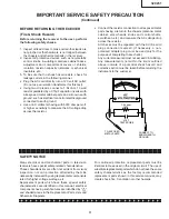
IMPORTANT SERVICE SAFETY PRECAUTION .................................................................................2
»
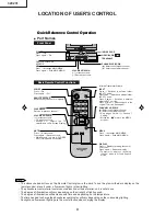
LOCATION OF USER'S CONTROL .....................................................................................................4
»
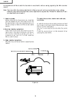
INSTALLATION AND SERVICE INSTRUCTIONS ................................................................................5
»
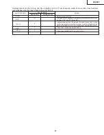
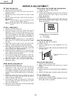
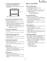
SERVICE ADJUSTMENT ...................................................................................................................10
»
WAVEFORMS .....................................................................................................................................13
»
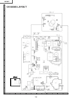
CHASSIS LAYOUT .............................................................................................................................14
»
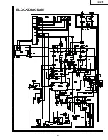
BLOCK DIAGRAM ..............................................................................................................................15
»
DESCRIPTION OF SCHEMATIC DIAGRAMS ...................................................................................16
»
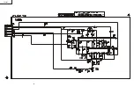
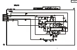
SCHEMATIC DIAGRAMS ...................................................................................................................17
»
PRINTED WIRING BOARD ASSEMBLIES ........................................................................................26
»
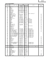
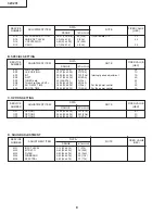
REPLACEMENT PARTS LIST ............................................................................................................30
»
PACKING OF THE SET ......................................................................................................................39
CONTENTS
SPEAKER
SIZE ........................................................ 12 x 6 cm oval (2 pcs.)
VOICE COIL IMPEDANCE ............................ 16 ohm at 400 Hz
ANTENNA INPUT IMPEDANCE
VHF/UHF ..................................................... 75 ohm Unbalanced
TUNING RANGES
VHF-Channels ...............................................................2 thru 13
UHF-Channels ............................................................ 14 thru 69
CATV Channels ...........................................................1 thru 125
(EIA, Channel Plan U.S.A.)
POWER INPUT ..................................................... 120V AC, 60 Hz
POWER RATING .................................................................. 135W
PICTURE SIZE ............................................ 3073cm
2
(476sq inch)
CONVERGENCE ............................................................. Magnetic
SWEEP DEFLECTION .................................................... Magnetic
FOCUS ............................................... Hi-Bi-Potential Electrostatic
INTERMEDIATE FREQUENCIES
Picture IF Carrier Frequency ..................................... 45.75 MHz
Sound IF Carrier Frequency ...................................... 41.25 MHz
Color Sub-Carrier Frequency .................................... 42.17 MHz
(Nominal)
AUDIO POWER
OUTPUT RATING .............. 3.0W + 3.0W (at 10% distortion and
Dual CH Operate)
Specifications are subject to change without
prior notice.
ELECTRICAL SPECIFICATIONS
MODEL
SERVICE MANUAL
32C
231
POWER
Summary of Contents for 32C231
Page 12: ...12 32C231 6 5 4 3 2 1 A B C D E F G H CHASSIS LAYOUT ...
Page 13: ...13 32C231 6 5 4 3 2 1 A B C D E F G H BLOCK DIAGRAM ...
Page 14: ...14 32C231 ...
Page 15: ...32C231 15 ...
Page 16: ...32C231 16 ...
Page 17: ...32C231 17 ...
Page 18: ...18 32C231 ...
Page 19: ...32C231 19 ...
Page 20: ...32C231 20 ...
Page 22: ...22 32C231 6 5 4 3 2 1 A B C D E F G H PWB A MAIN Unit Wiring Side ...
Page 23: ...23 32C231 6 5 4 3 2 1 A B C D E F G H PWB A MAIN Unit Chip Parts Side ...


