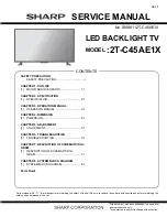
background image


SERVICE MANUAL

Ver.1

No. S88M112T-C45AE1X

LED BACKLIGHT TV

:2T-C45AE1X

MODEL

Parts marked with "

" are important for maintaining the safety of the set. Be sure to replace these parts with specified ones for maintaining the

safety and performance of the set.

This document has been published to be used for

after sales service only.

The contents are subject to change without notice.

SAFETY PRECAUTION

SAFETY PRECAUTION......................................i

CHAPTER 1. OUTLINE

[1]  MAJOR SERVICES PARTS........................... 1-1

CHAPTER 2. SPECIFICATION

[1]  SPECIFICATION............................................ 2-1

CHAPTER 3. OPERATION MANUAL

[1]  OPERATION MANUAL .................................. 3-1

CHAPTER 4. DIMENSION

[1]  DIMENSION................................................... 4-1

CHAPTER 5. ADJUSTMENT

[1]  ADJUSTMENT............................................... 5-1

CHAPTER 6. TROUBLESHOOTING

[1]  TROUBLESHOOTING................................... 6-1

CHAPTER 7. DESCRIPTION OF SCHEMATIC DIA-

GRAM

[1]  DESCRIPTION OF SCHEMATIC DIA-

GRAM ............................................................ 7-1

CHAPTER 8. SYSTEM BLOCK DIAGRAM

[1]  SYSTEM BLOCK DIAGRAM ......................... 8-1

Parts Guide

TopPage

CONTENTS

Summary of Contents for 2T-C45AE1X

Page 1: ...ly The contents are subject to change without notice SAFETY PRECAUTION SAFETY PRECAUTION i CHAPTER 1 OUTLINE 1 MAJOR SERVICES PARTS 1 1 CHAPTER 2 SPECIFICATION 1 SPECIFICATION 2 1 CHAPTER 3 OPERATION MANUAL 1 OPERATION MANUAL 3 1 CHAPTER 4 DIMENSION 1 DIMENSION 4 1 CHAPTER 5 ADJUSTMENT 1 ADJUSTMENT 5 1 CHAPTER 6 TROUBLESHOOTING 1 TROUBLESHOOTING 6 1 CHAPTER 7 DESCRIPTION OF SCHEMATIC DIA GRAM 1 DE...

Page 2: ...trol shafts escutcheon etc and measure the AC voltage drop across the resistor All checks must be repeated with the AC cord plug connection reversed If necessary a nonpolarized adaptor plug must be used only for the purpose of completing these checks Any reading of 0 74 Vrms this corresponds to 0 5 mA rms AC or more is excessive and indicates a potential shock hazard which must be corrected before...

Page 3: ...al lead solder by 40 C and as it has poor solder wettability you may be apt to keep the soldering bit in contact with the PWB for extended period of time However Since the land may be peeled off or the maximum heat resistance temperature of parts may be exceeded remove the bit from the PWB as soon as you confirm the steady soldering condition Lead free solder contains more tin and the end of the sol...

Page 4: ...DKEYMG912FM01 MAIN UNIT GENERAL N KSETLA735WJZZ POWER UNIT N KSETLA739WJZZ JOGKEY UNIT N KSETLA736WJZZ LED IR UNIT N KSETLA734WJZZ BLUETOOTH ANTENNA N RUNTKB588WJQZ WIFI UNIT N KSETLA740WJZZ TFT LCD OPEN CELL N CLCDTA452WEA4 PANEL ASSEMBLY N KSETLA741WJZZ LED BAR PRINTED WIRING BOARD ASSEMBLIES LCD PANEL MODULE UNIT ...

Page 5: ...ian Persian Thai Vietnamese Indonesia Hebrew Hindi Malay Power requirement AC 110 240 V 50 60 Hz y b d n a t S W 5 0 W 1 0 1 n o i t p m u s n o c r e w o P Dimensions without stand 1014 W g 581 H g 64 D mm with stand 1014 W g 622 H g 230 D mm Weight without stand with stand 9 0 kg 9 5 kg Operating temperature 0 C to 40 C As a part of policy of continuous improvement SHARP reserves the right to ma...

Page 6: ...2T C45AE1X 3 1 CHAPTER 3 OPERATION MANUAL 1 OPERATION MANUAL 1 2 Stand unit L 2 Stand unit R 1 Soft cushion 2 3 Screws Attaching the stand unit ...

Page 7: ...2T C45AE1X 4 1 CHAPTER 4 DIMENSION 1 DIMENSION Dimensional Drawing Unit mm 622 1014 992 1014 200 549 100 101 230 64 35 581 ...

Page 8: ...s available CH CH Changing channel UP DOWN Cursor Cursor INPUT button on remote controller DTV ATV HDMI1 1 HDMI2 INPUT 3 USB 3 Software upgrading 1 Make sure LCD TV is on 2 Insert USB device to the USB terminal at the LCD TV Make sure the latest software is installed in the USB device 3 Use below menu procedure to start upgradingsoftware version Menu Option System data Are you sure Yes 4 A few sec...

Page 9: ...ftware Development Dept 2 At checker confirm the version and perform operation inspection 2 VCOM ADJUSTMENT i Enter service mode key and go to VCOM TEST PATTERN Page ii Press Enter key at VCOM iii Adjust the flicker effect by pressing VOL of RC key iv Press Enter key after get the best value 3 SOFTWARE VERSION Confirmation on Software version will be done during meeting Model Software Package 2T C45...

Page 10: ...ance γ 2 2 8 Calculation Initial setting of R G B_HIGH 9 Set Initial setting of R G B_HIGH 10 Original WB adjustment is performed HIGH Set the specified gradation for point 2 fix the most faint colour to get reference value adjust others 2 colours to minus adjustment for reference value of point 2 11 Measurement HIGH Brightness Set R_HIGH G_HIGH G_HIGH G_HIGH B_HIGH G_HIGH 12 Calculation MAX lumin...

Page 11: ...correction value Rlow Glow Blow Rlow R1slope X 717 640 23 Set the reference value R G B of point 1 R1ʼ R1 Rlow 24 Adjusted value is writing at command MSET0003 25 Shut down the AC power Initial value at RGB 2 point 3664 Initial value at RGB 1 point 640 Adjustment value Teaching set send by engineering dept is set as reference Reference values for adjustment reference Equipment Luminance meter Mino...

Page 12: ...n iv HDCP 2 2 RECEIVER ID Main PWB QPWBXG912WJZZ Please refer to Caution Item for Production Display format example 11 13 NETWORK DIMMER PT1 DIMMER PT2 DIMMER PD1 DIMMER PD2 MAC ADDRESS BD ADDRESS WIFI MAC ADDRESS NETFLIX ESN WIDEVINE DEVICE ID PLAY READY HDCP 1 4 HDCP 2 2 HDCP 2 2 Receiver ID TEST NETWORK UPDATE 1 0 100 100 28 84 FA EB 03 09 00 00 00 00 00 11 CC B0 DA 60 40C 50 empty LCDTV2884FAE...

Page 13: ...ure Setting Backlight Brightness Contrast MAX Audio Output 400 Hz 1 8 of Maximum Audio Output 10W 10W VOL 19 AC Input 99VAC 264VAC 50Hz Wake UP LAN Off Model 2T C45AE1X Power Consumption Specification IEC600657 Standard Value Limit Value Power Consumption 82 W 10 Power Consumption at Stand by Operating 0 45 W 0 3W 0 6W 8 CHECKER PROCESS i Function Check Main PWB inspection functional check ii K MO...

Page 14: ... Setting OSD Language Setting A3KLLAE1SZ J I Y P B M N GENERAL 10000 0111 0111 10 MULTI 13 LANGUAGES ITEM CONDITION PROCEDURE Factory setting AC power off to exit the factory setting 1 Setting is done with test remote control 2 Press the ʻFactory Settingʼ key on the remote control continuously 3 When Green background appears on screen and ʻKʼ mark disappears setting is completed The followings are...

Page 15: ...to the next page c Then select Public Mode and switch it to ON state d Swithc the set by pushing ON OFF button or by plugged off the supply Start up from body key to display Public Mode During SPECIAL SERVICE KEY MODE same as Start upfrom b ody key meth od a All RC key is blocked during this period b By press One Push Button simultaneously with switch On the AC Cord c LED blinking GREEN repeatedly...

Page 16: ... MENU is displayed TVĐĂŶĐelPublicSĞƫŶŐ D Eh ĂŶĚchaŶŐetoŶormalPower ONmode ĐͿWheŶcursorisfocusoŶΖ y ChT aŶdpress OK key TVŶĞeddofollowiŶŐopera oŶ TVwillmemorizedofeachitem sse Ő xcept PICThR IDPORT Ϳ PublicmeŶudisappear IfPublicDodeis ON allpublicse ŶŐvalidimmediatelywithoutrebootTV IfPublicDodeis OFF allpublicse ŶŐwillŶotvalid 3 Public Mode Setting Value ĂͿ IŶi alizevalueofpublicSe PuďůŝĐ ĞƫŶŐ ĂĐƚ...

Page 17: ... r o w t n s e o d w o l e b e e s s r o t c a f y b d n a t s d e t a l e r n o i t c n u f L L A _ D E X I F o t g n i t c e l e s n e h W OFF TIMER Sleep EŽ ŽƉĞƌĂƟŽŶ K No signal OFF including the power management These items does not exist according to the model other than default 2 SHUT DOWN MODE dŚŝƐ ĨƵŶĐƟŽŶ ĚĞĐŝĚĞƐ ǁŚĞĂƚŚĞƌ ƐĐĂŶŶŝŶŐ ĚŝŐŝƚĂů ƚƵŶĞƌ ŝƐ ĞŶĂďůĞ Žƌ ĚŝƐĂďůĞĚ ǁŚĞŶ ƚŚĞ ƉŽǁĞƌ ŝƐ ƐƚĂŶĚ...

Page 18: ...ƐŽƵŶĚ ǀŽůƵŵĞ ƐŚŽƵůĚ ďĞ ƚƵƌŶĞĚ ĚŽǁŶ ƚŽ D y ŝŶ ƚŚŝƐ ƐƚĂƚĞ Ηs Z Η Η y Η Η dZ ΗŽƌ Η Z dZ Η ůŽŽƉ Ηs Z Η s Z dŚĞ ǀŽůƵŵĞ ŝƐ ŶŽƚ ĮdžĞĚ dŚĞ ƐŽƵŶĚ ǀŽůƵŵĞ ƚŽ ďĞ ĮdžĞĚ ďLJ ǀŽůƵŵĞ ĮdžĞĚ ŝƐ ĚĞƚĞƌŵŝŶĞĚ ŝŵŝƚ ŝŶ ƐĞƫŶŐ dŚĞ ƐŽƵŶĚ ǀŽůƵŵĞ ĨŽƌ ƚŚĞ KEͲƟŵĞƌ ǁĂŬĞ ƵƉ ƟŵĞƌ Ϳ ŝƐ ĮdžĞĚ ĂůƐŽ ǁŝƚŚŽƵƚ ĚŝƐƉůĂLJ ŽĨ ŵĞŶƵ ĞƐŝĚĞƐ ƚŚĞ ƐĞƫŶŐ ŝƐ ŵĂĚĞ ŝŵƉŽƐƐŝďůĞ ĂƐŝĐĂůůLJ ƚŚĞ ŵĂŶƵ ŝƐ ŶŽƚ ĚŝƐƉůĂLJĞĚ Ϳ dŚĞ ĨŽůůŽǁŝŶŐ ŬĞLJƐ ďĞĐŽŵĞ ŝŶǀĂůŝĚ ϭͿ ŽƵŶĚ ǀŽů...

Page 19: ... Selection Default Explanation Limit in setting Exception Remarks Selection between Respond and No respond loop provide Respond Respond No respond Inspection mode and hotel mode can be started irrespective of setting Option Default Explanation Limit in setting Exception Remarks Variable or Fixed loop enabled Variable Variable Fixed When receiving the sound select direct key AV POSITION key OPC FRE...

Page 20: ...ection between Variable and Fixed loop provide Variable If INPUT MODE START is set to normal input mode is not fixed Fixed direct tuning button FLASHBACk input None In the following case setting is cancelled and mode is changed to Variable 1 When the setting of input mode start is set to Stardand Normal Selection Default Explanation Limit in setting Exception Remarks Enable and Disable Disable The...

Page 21: ... function is active and remote is active too This function is active is active and remote is not active When set to On TV RCD TV does not accept the remote control None Selection Default Explanation Exception Limit in setting Remarks Off and On loop enabled Off The item decide whether Public mode setting menu are enabled or disabled The same item as PUBLIC MODE in the adjustment process menu OFF O...

Page 22: ...re harnesses and other cables properly in the set YES Is there the PS ONand PNL POW signal input at pins 14 and 16 of P9601 NO Check the PS ON signal line PNL POW signal line YES Are the DC DC converter outputs and the output voltages along the control lines as specified NO Check the DC DC converters and the control lines Replace defective parts as required 1 D 1 5V IC9601 2 BU 3 3V IC9602 3 BU 1 1...

Page 23: ...ect menu screen NO YES Is there the video signal input at pin 33 of IC3301 NO Check the line between pin 8 of J502 and pin 33 of IC3301 YES NO Check IC3301 and its peripheral circuits to SC3801 YES Check LVDS cable LCD controller incl panel and their periph eral circuits Are there the signal outputs pin 137 146 Pin 149 154 Pin 156 157 Are there the signal outputs pin of IC3301 to SC 3801 Is there ...

Page 24: ... i r e p s t i d n a 1 0 3 3 C I k c e h C O N s Pins 137 146 Pins 149 154 t u p t u o l a n g i s e h t e r e h t e r A YES Check LVDS cable LCD controller incl panel and their periph eral circuits Are there the signal outputs Pins 137 146 Pins 149 154 Pins 156 157 IC3301 3 Is INPUT 3 selected on the input select menu screen Select INPUT 3 on the input select menu screen to pick up the right inpu...

Page 25: ...ipheral circuits YES O N 2 0 7 1 C I f o 5 6 7 8 n i p t a t u p n i l a n g i s e r e h t s I Check connection between IC3301 and IC1702 and its periph eral circuits YES Is the L ch audio signal output at pin 26 27 30 31 of IC1702 normal NO Check IC1702 and its peripheral circuits Is the R ch audio signal output at pin 10 11 14 15 of IC1702 normal YES Are the audio signal L ch and R ch output at ...

Page 26: ..._DDR_A5 A_DDR_A6 A_DDR_A7 A_DDR_A8 A_DDR_A9 A_DDR_A10 A_DDR_A11 A_DDR_A12 A_DDR_A13 A_DDR_A14 A_DDR_BA0 A_DDR_BA1 A_DDR_BA2 A_DDR_RAS A_DDR_CAS A_DDR_WE A_DDR_CS A_DDR_ODT A_DDR_CKE A_DDR_RST A_DDR_CLK0 A_DDR_CLK0 R2003 100 R3329 4 7K R3321 33K D3 3V 002 R1118 0 R1117 0 C3324 10u C3301 10u R1513 100 R1524 100 R1534 10K R1511 10K R1519 100 R1521 100 D1517 EXA741WJQZ 5 6V D1518 EXA741WJQZ 5 6V D1520...

Page 27: ... 001 AA_DDR_DQ9 001 AA_DDR_DQS0 001 A_DDR_A2 001 A_DDR_A14 001 A_DDR_BA1 001 A_DDR_A11 001 AA_DDR_DQ15 001 AA_DDR_DQ13 001 AA_DDR_DQ14 001 A_DDR_RAS 001 A_DDR_CKE 001 A_DDR_A12 001 AA_DDR_DQ1 001 R3521 1K F R3522 1K F C3539 0 1u 10V C3538 0 1u 10V C3537 0 1u 10V C3536 0 1u 10V C3535 0 1u 10V C3534 0 1u 10V C3533 0 1u 10V C3532 0 1u 10V C3540 0 1u 10V C3541 0 1u 10V C3542 0 1u 10V C3543 0 1u 10V C3...

Page 28: ... R3118 10K R3106 10K FB3192 A371WJQZ R3101 33 1 2 3 4 5 6 7 8 R3102 33 1 2 3 4 5 6 7 8 R3103 33 R3110 33 CZ C3107 4 7u CKZ C3110 4 7u CKZ IXE079WJQZ A1 NC B1 NC C1 D1 E1 NC F1 NC G1 NC H1 NC J1 NC K1 NC L1 NC M1 N1 NC P1 NC P2 NC P3 P4 P5 P6 P7 NC P8 NC P9 NC P10 NC P11 NC P12 NC P13 NC P14 NC N14 NC M14 NC L14 NC K14 NC J14 NC H14 NC G14 NC F14 NC E14 NC D14 NC C14 NC B14 NC A14 NC A13 NC A12 NC ...

Page 29: ... ETH_MDI1 LAN_MDI_R ETH_MDI1 005 C2211 1000P ETH_MDI0 005 ETH_MDI0 005 T2201 ZA143WJQZ 1 2 3 6 7 8 9 10 11 14 15 16 ETH_MDI1 005 R2205 75 1 2 3 4 5 6 7 8 C2202 0 01u 25V C2203 0 01u 25V J2201 ZA151WJQZ 1 TD 2 TD 3 RD 4 5 6 RD 7 8 TO CPU 005 28 03 2018 MAIN04 ETH ...

Page 30: ...I 1 ARC Data 6 clk 2 I2C HDMI HPD0_IN D5V Sharp TUNER Asia RTUDAA116WJQZQ I2C IF IF Built in Demodulator 45 Power Unit LED Driver SP_ STBY SC3802 51 pin XIN XOUT X3301 XTAL 24 0MH z I2S_SCLK I2S_LRCLK LED_R LED G REMOT J501 1500mA USB IN SC1502 HDMI 2 Data 6 clk 2 HPD1_IN D5V I2C HDMI RC LED LED Green Red IR Reciever 3 3V REMOTE LED_G LED_R P2002 5 pin External LED RC 12V UART SC501 Service Jack H...

Page 31: ...2T C45AE1X 8 2 ...

Page 32: ...es for maintaining the safety and performance of the set This document has been published to be used for after sales service only The contents are subject to change without notice 2T C45AE1X 2T C45AE1X PartsGuide 1 PRINTED WIRING BOARD ASSEMBLIES 2 LCD PANEL 3 MAIN UNIT DKEYMG912FM01 2T C45AE1X 4 CABINET MECHANICAL PARTS 5 SUPPLIED ACCESSORIES 6 PACKING PARTS NOT REPLACE MENT ITEM ...

Page 33: ...Y AB V BALUN FB501 RBLN A589WJQZY AA V BALUN FB502 RBLN A589WJQZY AA V BALUN FB3301 RBLN A589WJQZY AA V BALUN FB9601 RBLN A589WJQZY AA V BALUN FB9602 RBLN A589WJQZY AA V BALUN FB9604 RBLN A589WJQZY AA V BALUN FB9606 RBLN A589WJQZY AA V BALUN FB9607 RBLN A589WJQZY AA V BALUN FB9616 RBLN A589WJQZY AA V BALUN FB510 RBLN A593WJQZY AA V BALUN FB511 RBLN A593WJQZY AA V BALUN FB512 RBLN A593WJQZY AA V BA...

Page 34: ...C KZA510WJPZY AB V CAPACITOR C3514 RC KZA510WJPZY AB V CAPACITOR C3520 RC KZA510WJPZY AB V CAPACITOR C504 RC KZA520WJQZY AA V CAPACITOR C513 RC KZA520WJQZY AA V CAPACITOR C514 RC KZA520WJQZY AA V CAPACITOR C1115 RC KZA520WJQZY AA V CAPACITOR C1501 RC KZA520WJQZY AA V CAPACITOR C3103 RC KZA520WJQZY AA V CAPACITOR C3322 RC KZA520WJQZY AA V CAPACITOR C3332 RC KZA520WJQZY AA V CAPACITOR C9652 RC KZA52...

Page 35: ...ER TLABNE421WJ01 AA V LABEL C1105 VCCCCZ1HH220JY AB V 22p 50V Ceramic C1106 VCCCCZ1HH220JY AB V 22p 50V Ceramic C9626 VCCCCZ1HH331JY AA V 330p 50V Ceramic C3317 VCCCCZ1HH391JY AA V 390p 50V Ceramic C3312 VCCCCZ1HH8R0DY AA V 80p 50V Ceramic C3313 VCCCCZ1HH8R0DY AA V 80p 50V Ceramic C507 VCKYCZ1AB104KY AB V 0 10 10V Ceramic C508 VCKYCZ1AB104KY AB V 0 10 10V Ceramic C509 VCKYCZ1AB104KY AB V 0 10 10V ...

Page 36: ...B V 0 10 10V Ceramic C3561 VCKYCZ1AB104KY AB V 0 10 10V Ceramic C3562 VCKYCZ1AB104KY AB V 0 10 10V Ceramic C3563 VCKYCZ1AB104KY AB V 0 10 10V Ceramic C9604 VCKYCZ1AB104KY AB V 0 10 10V Ceramic C9612 VCKYCZ1AB104KY AB V 0 10 10V Ceramic C9618 VCKYCZ1AB104KY AB V 0 10 10V Ceramic C9622 VCKYCZ1AB104KY AB V 0 10 10V Ceramic C9627 VCKYCZ1AB104KY AB V 0 10 10V Ceramic C9644 VCKYCZ1AB104KY AB V 0 10 10V ...

Page 37: ...RS CZ1JF000JY AA V 0 1 16W Metal Oxide R1507 VRS CZ1JF000JY AA V 0 1 16W Metal Oxide R1508 VRS CZ1JF000JY AA V 0 1 16W Metal Oxide R1533 VRS CZ1JF000JY AA V 0 1 16W Metal Oxide R1537 VRS CZ1JF000JY AA V 0 1 16W Metal Oxide R1540 VRS CZ1JF000JY AA V 0 1 16W Metal Oxide R1541 VRS CZ1JF000JY AA V 0 1 16W Metal Oxide R1542 VRS CZ1JF000JY AA V 0 1 16W Metal Oxide R1545 VRS CZ1JF000JY AA V 0 1 16W Metal...

Page 38: ...311 VRS CZ1JF103JY AA V 10k 1 16W Metal Oxide R3838 VRS CZ1JF103JY AA V 10k 1 16W Metal Oxide R3839 VRS CZ1JF103JY AA V 10k 1 16W Metal Oxide R9637 VRS CZ1JF103JY AA V 10k 1 16W Metal Oxide R9641 VRS CZ1JF103JY AA V 10k 1 16W Metal Oxide R9601 VRS CZ1JF104JY AA V 100k 1 16W Metal Oxide R9605 VRS CZ1JF104JY AA V 100k 1 16W Metal Oxide R9622 VRS CZ1JF104JY AA V 100k 1 16W Metal Oxide R9658 VRS CZ1JF...

Page 39: ...Q3301 VSLTC014EEB 1Y AB V LTC014EEBFS8TL Q3803 VSLTC014EEB 1Y AB V LTC014EEBFS8TL ZHNDALA7 R01E V E3301 PRDARB110WJFW V HEAT SINK PSPAZD642WJKZ V SPACER 4 CABINET MECHANICAL PARTS 1 KSETLA689WJ41 V RC LENS 2 KSETLA690WJ41 V KS CAB B 3 KSETLA691WJ41 AD V KEY BTN COVER 4 KSETLA692WJ41 V SIDE TERM ANG 5 KSETLA694WJ41 AD V KEY BTN 6 KSETLA696WJ41 AE V MAGNET 7 KSETLA698WJ41 AA V CAB B SCREW 8 KSETLA69...

Page 40: ...S STAND L X5 KSETLA687WJ41 AW V KS STAND R X6 KSETLA700WJ41 AC V SCREW FOR STAND X4 X7 TGAN C490WJZZ V WARRANTY CARD FOR MALAYSIA X7 TGAN B249WJN2 AB V WARRANTY CARD FOR PHILIPINES X7 TGAN C422WJZZ V WARRANTY CARD FOR THAILAND X7 TGAN B383WJN1 AD V WARRANTY CARD FOR VIETNAM 5 SUPPLIED ACCESSORIES ...

Page 41: ...0WJZZ AF V HOSO PP S5 SPAKFC482WJ41 AE V LAYER PAD S6 CPAKFC545WJ41 V FRONT EPE UNIT S7 ZTAPEH48TA35E V TAPE FOR PACK S8 SPAKPC407WJ41 AC V PE BAG S9 ZTAPEQ25 150E V PAPER TAPE X1 CBATUA024WJ45 V KS SCREW BAT X2 RRMCGB289WJSA AW V REMOTE CONTROL X3 KSETLA687WJ41 AW V KS STAND R X4 KSETLA688WJ41 AW V KS STAND L X5 CINS H106WE01 V MANUAL SET ...

Page 42: ...2T C45AE1X Packing Assembly X1 S5 S1 S2 S3 S4 S8 S6 S7 X5 X4 X3 X2 S9 S5 S8 S9 ...

Page 43: ...1 Remote control unit x 1 2 AAA size battery x 2 3 Initial setup guide 4 Stand unit 5 Stand base with letter R 6 Stand base with letter L 7 Screws m 4 Supplied accessories ...

Page 44: ...rt of this publication may be reproduced stored in a retrieval system or transmitted in any form or by any means electronic mechanical photocopying recording or otherwise without prior written permission of the publisher COPYRIGHT XXXX BY SHARP CORPORATION ALL RIGHTS RESERVED COPYRIGHT 2018 BY SHARP CORPORATION SHARP MANUFACTURING CORPORATION M SDN BHD PQA DEPARTMENT Batu Pahat Johor Malaysia RQ32...

Reviews: