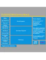
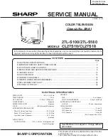
background image

1

27L-S100/27L-S180
CL27S10/CL27S18

COLOR TELEVISION

Chassis No. SN-91

In the interests of user-safety (Required by safety regulations in some countries) the set should be restored to its
original condition and only parts identical to those specified should be used.

S39D927L-S100

MODELS

»

 ELECTRICAL SPECIFICATIONS ......................................................................................................... 1

»

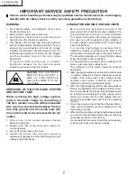
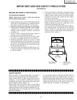
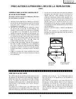
 IMPORTANT SERVICE SAFETY PRECAUTION ................................................................................ 2

»

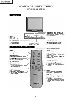
 LOCATION OF USER'S CONTROL ..................................................................................................... 6

»

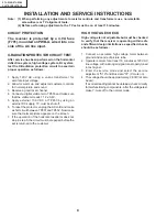
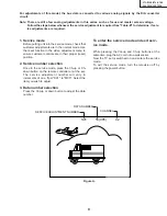
 INSTALLATION AND SERVICE INSTRUCTIONS ................................................................................ 8

»

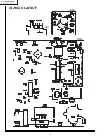
 CHASSIS LAYOUT ............................................................................................................................. 14

»

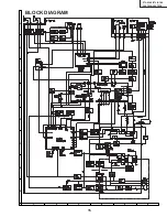
 BLOCK DIAGRAM ............................................................................................................................. 15

»

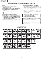
 SCHEMATIC DIAGRAMS ................................................................................................................... 16

»

 PRINTED WIRING BOARD ASSEMBLIES ........................................................................................ 26

»

 REPLACEMENT PARTS LIST ........................................................................................................... 29

»

 PACKING OF THE SET ..................................................................................................................... 36

Page

POWER INPUT ................................................... 120 V  AC 60 Hz

POWER RATING .................................................................. 110 W

PICTURE SIZE ........................................... 2,187cm

2

 (339sq inch)

CONVERGENCE ............................................................. Magnetic

SWEEP DEFLECTION ..................................................... Magnetic

FOCUS ............................................... Hi-Bi-Potential Electrostatic

INTERMEDIATE FREQUENCIES

Picture IF Carrier Frequency ..................................... 45.75 MHz

Sound IF Carrier Frequency ...................................... 41.25 MHz

Color Sub-Carrier Frequency ..................................... 42.17 MHz

 (Nominal)

AUDIO POWER

OUTPUT RATING .............. 1.3W + 1.3W (at 10% distortion and

Dual CH Operate)

SHARP CORPORATION

This document has been published to be used for after
sales service only.
The contents are subject to change without notice.

CONTENTS

ELECTRICAL SPECIFICATIONS

Specifications are subject to change without
prior notice.

SPEAKER

SIZE ...................................................................... 8 cm (Round)

VOICE COIL IMPEDANCE ............................. 32 ohm at 400 Hz

ANTENNA INPUT IMPEDANCE

VHF/UHF .................................................... 75 ohm Unbalanced

TUNING RANGES

VHF-Channels .............................................................. 2 thru 13

UHF-Channels ............................................................ 14 thru 69

CATV Channels .......................................................... 1 thru 125

(EIA, Channel Plan U.S.A.)

SERVICE MANUAL

27L-S100/27L-S180
CL27S10/CL27S18

Summary of Contents for 27L-S100

Page 1: ... 187cm2 339sq inch CONVERGENCE Magnetic SWEEP DEFLECTION Magnetic FOCUS Hi Bi Potential Electrostatic INTERMEDIATE FREQUENCIES Picture IF Carrier Frequency 45 75 MHz Sound IF Carrier Frequency 41 25 MHz Color Sub Carrier Frequency 42 17 MHz Nominal AUDIO POWER OUTPUT RATING 1 3W 1 3W at 10 distortion and Dual CH Operate SHARP CORPORATION This document has been published to be used for after sales ...

Page 2: ...libration of this meter should be checked periodically 3 High voltage should always be kept at the rated value no higher Operation at higher voltages may cause a failure of the picture tube or high voltage circuitry and also under certain conditions may produce radiation in exceeding of desirable levels 4 When the high voltage regulator is operating properly there is no possibility of an X radiati...

Page 3: ...acity networks mechanical insulators etc 3 To be sure that no shock hazard exists check for leakage current in the following manner Plug the AC cord directly into a 120 volt AC outlet Do not use an isolation transformer for this test Using two clip leads connect a 1 5k ohm 10 watt resistor paralleled by a 0 15µF capacitor in series with all exposed metal cabinet parts and a known earth ground such...

Page 4: ...anipuler le tube image qu en porant des lunettes incassables et qu après avoir déchargé totalement la haute tension LIMITES DES RADIATIONS X ET DE LA HAUTE TENSION 1 Tout le personnel réparateur doit être instruit des instructions et procédés relatifs aux radiations X Le tube image seule source de rayons X dons les téleviseurs transistorisés n émet pourtant pas de rayons mesurables si la haute ten...

Page 5: ...cité les isolateurs mécaniques etc 3 S assurer qu il n y ait pas de danger d électrocution en vérifiant la fuite de courant de la facon suivante Brancher le cordon d alimentation directem ent à une prise de courant de 120V Ne pas utiliser de transformateur d isolation pour cet essai A l aide de deux fils à pinces brancher une résistance de 1 5 kΩ 10 watts en parallèle avec un condensateur de 0 15µ...

Page 6: ...6 27L S100 27L S180 CL27S10 CL27S18 LOCATION OF USER S CONTROL 27L S100 CL27S10 ...

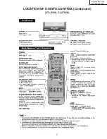
Page 7: ...7 27L S100 27L S180 CL27S10 CL27S18 LOCATION OF USER S CONTROL Continued 27L S180 CL27S18 ...

Page 8: ...7 If the operation of the horizontal oscillator does not stop in step 5 the circuit must be repaired before the set is returned to the customer HIGH VOLTAGE CHECK High voltage is not adjustable but must be checked to verify that the receiver is operating within safe and efficient design limitations as specified checks should be as follows 1 Connect an accurate high voltage meter between ground and...

Page 9: ... in the normal mode Use the reset function in the video adjustment menu to ensure customer controls are in their proper reset position 2 Service number selection Once in the service mode press the Ch up or Ch down button on the remote controller or at the set The service adjustment number will vary in increments of one from S01 to M05 Select the item you wish to adjust 3 Data number selection Pres...

Page 10: ...S22 OSD SETUP 00 00 03 Must be set to 00 S23 TUNER SETUP 00 00 01 Must be set to 00 OP OPTION Set to each model 30 00 FF Must be set to 26 27L S100 3E 27L S180 M01 INPUT LEVEL 0A 00 0F M02 ST VCO 20 00 3F M03 FILTER 1C 00 3F M04 WIDE BAND 20 00 3F M05 SPECTRAL 1B 00 3F NECESSARY UNNECESSARY ADJUSTMENT NOTES PART REPLACED IC2001 IC2101 X IC3001 X CRT X IC201 X X Data is stored in IC2101 The adjustm...

Page 11: ...s to the point where raster is barely seen 7 Adjust the service adjustments S11 red S12 green and S13 blue to obtain a good grey scale with normal whites at low brightness level 8 Select the service adjustment S19 and reset data to 00 Select the service adjustment S03 and reset data to obtain normal color level 9 Remove oscilloscope and reset the master screen control to obtain normal brightness r...

Page 12: ...nter the service mode and select the service adjustment S18 3 A black text box appears on the screen see Figure B below 4 Adjust S18 data value so that text box is positioned in the center of the screen 3 58MHz Trap Adjustment 1 Receive a good local channel 2 Enter the service mode and select the service adjustment S16 3 This is a two position adjustment 00 is ON 01 is OFF 4 Adjust data value to 0...

Page 13: ...o pin 14 of IC3001 Stereo pilot signal 9 4kHz 600mVrms 2 Enter the service mode and select the service adjustment M03 3 Adjust the data at the point where OK appears on the screen The OK represents the approximate center of the adjustable range of the data Separation Adjustment 1 Connect the rms voltmeter to pin 39 of IC3001 2 Receive the following composite stereo signal 1 Composite stereo signal...

Page 14: ...14 27L S100 27L S180 CL27S10 CL27S18 8 7 10 9 6 5 4 3 2 1 A B C D E F G H 6 5 4 3 2 1 A B C D E F G H CHASSIS LAYOUT PWB B PWB H PWB A ...

Page 15: ...15 27L S100 27L S180 CL27S10 CL27S18 17 16 19 18 15 14 13 12 11 10 6 5 4 3 2 1 A B C D E F G H BLOCK DIAGRAM ...

Page 16: ...l picture unless otherwise indicated 2 All voltages measured with 1000µ V B W or Color signal WAVEFORM MEASUREMENT CONDITIONS 1 Photographs taken on a standard gated color bar signal the tint setting adjusted for proper color The wave shapes at the red green and blue cathodes of the picture tube depend on the tint color level and picture control 2 indicates waveform check points See chart waveform...

Page 17: ...17 27L S100 27L S180 CL27S10 CL27S18 17 16 19 18 15 14 13 12 11 10 6 5 4 3 2 1 A B C D E F G H SCHEMATIC DIAGRAM CRT and FRONT AV Units ...

Page 18: ...18 27L S100 27L S180 CL27S10 CL27S18 8 7 10 9 6 5 4 3 2 1 A B C D E F G H MODEL 27L S100 CL27S10 SCHEMATIC DIAGRAM MAIN 1 Unit ...

Page 19: ...19 27L S100 27L S180 CL27S10 CL27S18 17 16 19 18 15 14 13 12 11 10 ...

Page 20: ...20 27L S100 27L S180 CL27S10 CL27S18 8 7 10 9 6 5 4 3 2 1 A B C D E F G H MODEL 27L S100 CL27S10 SCHEMATIC DIAGRAM MAIN 2 Unit ...

Page 21: ...21 27L S100 27L S180 CL27S10 CL27S18 17 16 19 18 15 14 13 12 11 10 ...

Page 22: ...22 27L S100 27L S180 CL27S10 CL27S18 8 7 10 9 6 5 4 3 2 1 A B C D E F G H MODEL 27L S180 CL27S18 SCHEMATIC DIAGRAM MAIN 1 Unit ...

Page 23: ...23 27L S100 27L S180 CL27S10 CL27S18 17 16 19 18 15 14 13 12 11 10 ...

Page 24: ...24 27L S100 27L S180 CL27S10 CL27S18 8 7 10 9 6 5 4 3 2 1 A B C D E F G H MODEL 27L S180 CL27S18 SCHEMATIC DIAGRAM MAIN 2 Unit ...

Page 25: ...25 27L S100 27L S180 CL27S10 CL27S18 17 16 19 18 15 14 13 12 11 10 ...

Page 26: ...26 27L S100 27L S180 CL27S10 CL27S18 8 7 10 9 6 5 4 3 2 1 A B C D E F G H PRINTED WIRING BOARD ASSEMBLIES PWB A MAIN Unit Wiring Side 6 5 4 3 2 1 A B C D E F G H ...

Page 27: ...27 27L S100 27L S180 CL27S10 CL27S18 17 16 19 18 15 14 13 12 11 10 6 5 4 3 2 1 A B C D E F G H PWB A MAIN Unit Chip Parts Side ...

Page 28: ...28 27L S100 27L S180 CL27S10 CL27S18 8 7 10 9 6 5 4 3 2 1 A B C D E F G H 6 5 4 3 2 1 A B C D E F G H PWB H FRONT AV Unit Wiring Side PWB B CRT Unit Wiring Side ...

Page 29: ...TS REPLACEMENT Replacement parts which have these special safety characteristics identified in this manual electrical components having such features are identified by å and shaded areas in the Replacement Parts Lists and Schematic Diagrams The use of a substitute replacement part which dose no have the same safety characteristic as the factory recommended replacement parts shown in this service m...

Page 30: ...301 VP XF8R2K0000 J Peaking 8 2µH AB L302 RCiLi0613CEZZ J IF Coil AE L401 VP XF6R8K0000 J Peaking 6 8µH AB L402 VP XF3R3K0000 J Peaking 3 3µH AB L403 VP XF8R2K0000 J Peaking 8 2µH AB L404 VP XF8R2K0000 J Peaking 8 2µH AB L421 VP XF680K0000 J Peaking 68µH AB L672 RCiLZ0101MEZZ M Coil AE å L701 RCiLF0025PEZZ M Coil AE å L702 RCiLF0025PEZZ M Coil AE å L705 RCiLP0179CEZZ J Coil AD L729 RCiLP0179CEZZ J...

Page 31: ...225M J 2 2 50V EL AB C909 VCEA0A1HW225M J 2 2 50V EL AB C910 VCKYCY1HB681K J 680p 50V Ceramic AA 27L S180 CL27S18 C911 VCKYCY1HB681K J 680p 50V Ceramic AA 27L S180 CL27S18 C922 VCEA0A1HW335M J 3 3 50V EL AB 27L S180 CL27S18 C923 VCEA0A1HW335M J 3 3 50V EL AB 27L S180 CL27S18 C931 VCKYCY1EB183K J 0 018 25V Ceramic AA 27L S180 CL27S18 C932 VCKYCY1EB183K J 0 018 25V Ceramic AA 27L S180 CL27S18 C951 V...

Page 32: ... 15k 1 2W Carbon AA R453 VRD RA2EE683J J 68k 1 4W Carbon AA R454 VRD MN2BE102J J 1 0k 1 8W Carbon AA R456 VRD MN2BE682J J 6 8k 1 8W Carbon AA R458 VRD MN2BE152J J 1 5k 1 8W Carbon AA å R501 VRN RL3ABR56J J 0 56 1W M Film AA R510 VRD MN2BE471J J 470 1 8W Carbon AA R511 VRD RA2BE823G J 82k 1 8W Carbon AB R512 VRD RA2BE124G J 120k 1 8W Carbon AA R513 VRD RA2BE473J J 47k 1 8W Carbon AA R514 VRD MN2BE1...

Page 33: ...1 VRD MN2BE222J J 2 2k 1 8W Carbon AA R2202 VRS CY1JF103J J 10k 1 16W M Ox AA R2203 VRS CY1JF184J J 180k 1 16W M Ox AA R2211 VRD MN2BE222J J 2 2k 1 8W Carbon AA R2212 VRS CY1JF682J J 6 8k 1 16W M Ox AA R2213 VRS CY1JF333J J 33k 1 16W M Ox AA R2401 VRS CY1JF101J J 100 1 16W M Ox AA R2402 VRS CY1JF101J J 100 1 16W M Ox AA R2403 VRD MN2BE101J J 100 1 8W Carbon AA R2404 VRD MN2BE101J J 100 1 8W Carbon...

Page 34: ...91J J 390p 50V Ceramic AA C852 VCCSPA1HL331J J 330p 50V Ceramic AA C853 VCCSPA1HL391J J 390p 50V Ceramic AA C854 RC KZ0024CEZZ J 0 001 2kV Ceramic AC C883 VCEA0A1HW106M J 10 50V EL AB RESISTORS M Ox Metal Oxide R851 VRD RA2BE470J J 47 1 8W Carbon AA R852 VRD RA2BE181J J 180 1 8W Carbon AA R853 VRD RA2BE121J J 120 1 8W Carbon AA R855 VRD RA2BE471J J 470 1 8W Carbon AA R856 VRD RA2BE221J J 220 1 8W ...

Page 35: ...KA M Button Ch up down AD 2 GCABB1148MEKA M Rear Cabinet AZ CABINET PARTS 1 1 1 2 1 4 1 3 1 2 1 5 CABINET PARTS LOCATION MISCELLANEOUS PARTS å ACC701 QACCD3065CESA M AC Cord AG QCNW 0130MEZZ M Connecting Cord AF QCNW 0134MEZZ M Connecting Cord AE QCNW 0166MEZZ M Connecting Cord AD QCNW 0167MEZZ M Connecting Cord AC QCNW 0239MEZZ M Connecting Cord AH SP1 VSP0080PBL4YS M Speaker L AG SP2 VSP0080PBL4...

Page 36: ...180 CL27S10 CL27S18 REAR Use 22 staples fix the packing case Bar Code Label Packing Case Serial Number Label MARK Not replacement items Number Card FRONT Buffer Material Polyethylene Sack Polystyrene Bag Operation Manual Guarantee Card Infrared R C Unit Batteries PACKING OF THE SET ...

Page 37: ...Ref No Part No Description Code Ref No Part No Description Code 37 27L S100 27L S180 CL27S10 CL27S18 ...

Page 38: ...part of this publication may be reproduced stored in a retrieval system or transmitted in any form or by any means electronic mechanical photocopying recording or otherwise without prior written permission of the publisher SHARP CORPORATION AV Systems Group Quality Reliability Control Center Yaita Tochigi 329 2193 Japan TQ0615 S Mar 1999 Printed in Japan KI KG ...

Reviews: