background image

1

13VT-R100/R150
13VT-CR10

CONTENTS

Page

»

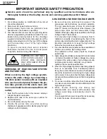
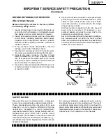
IMPORTANT SERVICE SAFETY PRECAUTION ............................................................................ 2

»

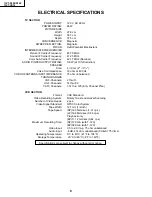
ELECTRICAL SPECIFICATIONS .................................................................................................... 6

»

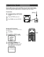
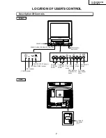
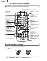
LOCATION OF USER’S CONTROL ................................................................................................ 7

»

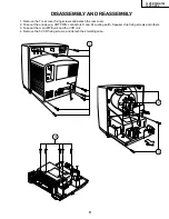
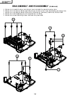
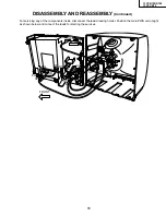
DISASSEMBLY AND REASSEMBLY .............................................................................................. 9

»

INSTALLATION AND SERVICE INSTRUCTIONS ......................................................................... 12

»

PRECAUTIONS IN REASSEMBLING ........................................................................................... 17

»

FUNCTION OF MAJOR MECHANICAL PARTS ............................................................................ 18

»

ADJUSTMENT, REPLACEMENT AND ASSEMBLY OF MECHANICAL UNITS ........................... 20

»

ADJUSTMENT OF THE VCR ELECTRICAL CIRCUITRY ............................................................ 40

»

TROUBLESHOOTING ................................................................................................................... 42

»

CHASSIS LAYOUT ........................................................................................................................ 54

»

BLOCK DIAGRAM OF TV SECTION ............................................................................................ 56

»

BLOCK DIAGRAM OF VCR SECTION ......................................................................................... 58

»

OVERALL SCHEMATIC DIAGRAM ............................................................................................... 68

»

DESCRIPTION OF SCHEMATIC DIAGRAM ................................................................................. 70

»

PRINTED WIRING BOARD ASSEMBLIES ................................................................................... 84

»

REPLACEMENT PARTS LIST ....................................................................................................... 88

»

PACKING OF THE SET ............................................................................................................... 103

In the interests of user-safety (Required by safety regulations in some countries ) the set should be restored to its
original condition and only parts identical to those specified should be used.

SHARP CORPORATION

This document has been published to be used for
after sales service only.
The contents are subject to change without notice.

SERVICE MANUAL

S51T413VT-R10

TV/VCR COMBINATION

Chassis No. B00A

13VT-R100
13VT-R150
13VT-CR10

MODELS

Summary of Contents for 13VT-CR10

Page 1: ...OF TV SECTION 56 BLOCK DIAGRAM OF VCR SECTION 58 OVERALL SCHEMATIC DIAGRAM 68 DESCRIPTION OF SCHEMATIC DIAGRAM 70 PRINTED WIRING BOARD ASSEMBLIES 84 REPLACEMENT PARTS LIST 88 PACKING OF THE SET 103 In the interests of user safety Required by safety regulations in some countries the set should be restored to its original condition and only parts identical to those specified should be used SHARP COR...

Page 2: ...ith a meter to be certain that the high voltage does not exceed the specified value and that it is regulating correctly 5 Do not use a picture tube other than that specified or make unrecommended circuit modifications to the high voltage circuitry 6 When trouble shooting and taking test measurements on a receiver with excessive high voltage avoid being unnecessarily close to the receiver Do not op...

Page 3: ... a return to the chassis antenna metal cabinet screw heads knobs and control shafts escutcheon and etc and measure the AC voltage drop across the resistor AII check must be repeated with the AC line cord plug connection reversed If necessary a non polarized adapter plug must be used only for the purpose of completing these check Any current measured must not exceed 0 5 milliamp Any measurements no...

Page 4: ... autre que celui spécifié et ne pas effectuer de modifications déconseillées du circuit à haute tension 6 Lors de la recherche des pannes et des mesures d essai sur un récepteur qui présente une haute tension excessive éviter de s approcher inutilement du récepteur Ne pas faire fonctionner le récepteur plus longtemps que nécessaire pour localiser la cause de la tension excessive AVERTISSEMENT 1 N ...

Page 5: ...étalonnées pour haute tension puissance etc Les pièces de remplacement qui présentent ces caractéristiques sont identifiées dans ce manuel les pièces électriques qui présentent ces particularités sont PRECAUTIONS A PRENDRE LORS DE LA REPARATION Suite 1 Inspecter tous les faisceaux de câbles pour s assurer que les fils ne soient pas pincés ou qu un outil ne soit pas placé entre le châssis et les au...

Page 6: ...PEDANCE 75 ohm unbalanced TUNING RANGES VHF Channels 2 thru 13 UHF Channels 14 thru 69 CATV Channels 1 14 thru 125 EIA Channel Plan VCR SECTION Format VHS Standard Video Recording System Rotary Two Head Helical Scanning Number of Video Heads 2 pcs Video Signal Standard NTSC Color System Tape Width 12 7mm 1 2inch Tape Speed SP 33 35mm sec 1 31 i p s LP 16 68mm sec 0 66 i p s Play back only EP 11 12...

Page 7: ...Jacks POWER button POWER indicator REC indicator PROGRAM TIMER indicator TAMPER PROOF indicator CHANNEL UP DOWN buttons PLAY button SENSOR AREA FOR REMOTE CONTROL ANT CABLE TERMINAL 75 POWER WAKE UP TIMER REC PROGRAM TIMER TAMPER PROOF EZ PLAY button REC button STOP EJECT button FF Forward Video Search button REW Reverse Video Search button VOLUME UP DOWN buttons ...

Page 8: ...ress Mutes sound Press again Restores sound to previous level Press the MUTE button to enter the CLOSED CAPTION mode automatically if the signal contains CC information VOLUME UP DOWN CHANNEL UP DOWN TRACKING Used to select the CHANNEL Used to adjust the TRACKING while playing the tape TAMPER PROOF Used to block changes to current operating mode FF Used to fast forward the tape or to conduct Forwa...

Page 9: ...detach the rear cover 2 Take out the anode cap CRT PWB connectors K and M coating earth Speaker chip fixing screws and others 3 Take out the main PWB unit and the VCR unit 4 Remove the 5 VCR fixing screws and detach the shielding case DISASSEMBLY AND REASSEMBLY 1 3 2 K M 4 ...

Page 10: ...ssis angle fixing screws and remove the 1 head amp shielding case fixing screw 7 Remove the 3 mechanism chassis fixing screws and detach the mechanism chassis from the main PWB 8 Remove the 3 main PWB fixing screws and detach the main PWB 9 Remove the 2 power PWB fixing screws and detach the power PWB DISASSEMBLY AND REASSEMBLY Continued 5 7 7 6 8 9 ...

Page 11: ...ND REASSEMBLY Continued For servicing any of the components inside disconnect the lead dressing holder Position the main PWB unit upright as shown below and connect the leads for starting the services GC GR GR M K FRONT SP OC PG OR OR PG GC OC ...

Page 12: ...nal DC power supply and short together TP651 and TP652 Once the TV set operates normally again remove the short between TP651 and TP652 HIGH VOLTAGE CHECK High voltage is not adjustable but must be checked to verify that the receiver is operating within safe and efficient design limitations as specified checks should be as follows 1 Connect an accurate high voltage meter between ground and anode o...

Page 13: ... are required 3 Data number selection Press the volume up or down button to adjust the data number in the upper right hand side of the screen 1 Service mode Before putting unit into the service mode check that customer adjustments are in the normal mode use the reset function in the video adjust menu to ensure customer controls are in their proper reset position To enter the service mode Plug in a...

Page 14: ...31 RF AGC 18 0 63 V AMP 32 0 63 PIF VCO 40 0 127 R CUT OFF 0 0 255 G CUT OFF 0 0 255 B CUT OFF 0 0 255 G GAIN 128 0 255 B GAIN 128 0 255 MUTE 0 0 2 0 Normal raster 1 no Y 2 No Vertical ENERGY SAVE 45 0 45 BALANCE 32 0 63 TEXT BOX 15 0 127 TEXT PICTURE 20 0 80 CCD LEVEL 10 0 24 OPTION VCR 39 0 63 13VT R100 R150 Must be set to 39 OPTION TV 31 0 255 Data is stored in IC2003 The adjustment is needed t...

Page 15: ...ain a good grey scale with normal whites at low brightness level 7 Select the service adjustment item MUTE and reset data to 0 Select service adjustment item COLOR and reset data to obtain normal color level White Balance Adjustment 1 Select a good local channel 2 Enter the service mode and select the service adjustment item COLOR and set to 0 minimum color COLOR does not have to be adjusted if yo...

Page 16: ... Position Adjustment 1 Select a good local channel 2 Enter the service mode and select the service adjustment item H PHASE 3 Adjust H PHASE data value so that picture is centered Caption Position Adjustment Horizontal 1 Select a good local channel 2 Enter the service mode and select the service adjustment item TEXT BOX 3 A black text box appears on the screen See Figure B below 4 Adjust TEXT BOX d...

Page 17: ...the cassette controller in position This method is used when the mechanism has been already set on its PWB COUPLING THE MECHANISM TO THE PWB Match the mechanism s projections with the two symbols round reference and oval sub reference on the main PWB Place the mechanism straight down in position with due care so that the mechanism chassis s outer edges should not damage any parts nearby Tighten up...

Page 18: ... 13 Reverse guide lever ass y Pulls out the tape and controls the tape drive train height with the upper and lower guides 16 Pinch roller lever ass y Press fits the tape to the capstan during tape running 18 Loading motor A motive power which drives the mechanism It transmits the power to the master cam and cas sette housing control ass y Full Erase Head Supply Pole Base Ass y Supply Reel Disk Sup...

Page 19: ... guide roller via the loading gear T and applies the tape around the drum assembly as well as transmits the power to the loading gears 1 Slow brake Gets in contact with the capstan D D motor linking to the master cam in the slow still mode and brakes it to a certain degree 3 Capstan D D motor A motive power which runs the tape It transmits the power via the Drive belt 4 Drive belt Transmits the po...

Page 20: ...de height adjustment Hex Wrench 1 5 mm JiGHW0015 AE This Jig is used with the tension gauge Rotary transformer clear ance adjusting jig There are two gauges used for the tension measurements 300 g and 2 0kg Hex Wrench 1 2 mm JiGHW0012 AE 4 Torque Driver JiGTD1200 CB ADJUSTMENT REPLACEMENT AND ASSEMBLY OF MECHANICAL UNITS The explanation given below relates to the on site general service field serv...

Page 21: ... This Jig is used for height adjustment of the reverse guide Guide roller height adjustment drive 10 Alignment Tape X value adjustment gear type screw driver Reverse Guide Height Adjusting Jig Video Audio Hi Fi Audio Track 525 Monoscope 7k 58µm NTSC Color Bar 1k 58µm For X value adjustment 11 12 13 JiGDRiVERH 4 JiGDRiVER 6 JiGRVGH F18 AP BM BU VRONBZGS VROEBZCS CB 525 Monoscope 525 Monoscope 7k 1k...

Page 22: ...er drum ass y Poor S N ratio no color Poorflatnessoftheenve lope with alignment tape Clean rubber and rubber contact area with the specified cleaning liquid Pinch roller No tape running tape slack No tape running tape slack no fast forward rewind motion Reel belt Cassette not loaded or unloaded Idler ass y Tension band ass y Screen swaying Loading Motor Limiter pulley Supply take up Main brake lev...

Page 23: ...ment of teeth of casecon drive gear and drive angle gear causes malfunction The cassette cannot be set load and ejection are repeated 3 In the case when you use the magnet screw driver never approach the magnet driver to the A C head FE head and drum 4 When installing or removing take care so that the cassette housing control and tool do not contact the guide pin or drum 5 After installing the cas...

Page 24: ...l so that grease does not adhere to the brake surface Reassembly Take up reel disk 1 Clean the reel disk shaft and apply grease SC 141 to it 2 Align the phase of the reel disk to that of the reel relay gear and to install a new take up reel disk onto the shaft 3 Check the reel disk height and reassemble the take up main brake ass y Note 1 Take care so that the Tu main brake ass y is not damaged Ta...

Page 25: ... measurement CHECKING AND ADJUSTMENT OF TAKE UP TORQUE IN REWIND MODE Remove the cassette housing control assembly Aftershort circuitingTP7701andTP7702provided at the left on the main PWB plug in the power cord then turn on the power Setting 1 Set a torque gauge to zero on the scale Place it on the supply reel disk 2 Press the rewind button 3 To calculate the remaining capacity slowly rotate the t...

Page 26: ...ode x3 and make sure that the winding up torque is within setting Adjustment If the playback winding up torque is not within the setting replace the limiter pulley assembly Note When the torque cassette is set put a weight 500g to prevent rise CHECKING AND ADJUSTMENT OF TAKE UP TORQUE IN VIDEO SEARCH REWIND MODE Remove the cassette housing control assembly After short circuiting TP7701 and TP7702 ...

Page 27: ...g in the power cord then turn on the power Checking Press the play button to set the playback mode CCW 500g T 120 Weight to prevent float 500g Figure 1 13 Figure 1 14 Checking 1 Set a cassette tape push the REC button to place the unit in the SP record mode Now check the tension pole position 1 Detach the pinch roller from the capstan shaft Do not separate excessively Or the pinch lever and pinch ...

Page 28: ...n pole 500g Weight to prevent float 500g Cassette torque meter Tension pole adjuster adjusting range Adjust so that the delta mark of tension pole adjuster is within 90 range left right CHECKINGANDADJUSTMENTOFRECORD PLAYBACK BACK TENSION Remove the cassette housing control assembly After short circuiting TP7701 and TP7702 pro vided at the left on the main PWB plug in the power cord then turn on th...

Page 29: ...ithin the setting CW direction 8 8 to 23 5mN m 90 to 240gf cm CCW direction 3 9 to 9 8mN m 40 to 100gf cm Tension arm Tension spring CW CCW CW Supply reel disk Torque gauge Torque gauge CCW Take up reel disk A B Checking the brake torque at the take up side Figure 1 22 Remove the cassette housing control assembly After short circuiting TP7701 and TP7702 pro vided at the left on the main PWB plug i...

Page 30: ...0 N m 1 5 to 2 0kgf cm Figure 1 24 Solder Never touch the head 10 8mm 10 8mm A C head plate 2 Spring 1 Azimuth screw Height screw Tilt screw Figure 1 23 3 Replacement 1 Solder the removed PWB to the new head assembly 2 Adjust the height from the A C head arm lower sur face to the A C head plate to 10 8mm with slide calipers 3 places of azimuth screw section tilt screw section and A C head front se...

Page 31: ...ight adjustment box driver JiGDRiVER11055 13 38mm Box driver Height adjusting nut CCW Reverse guide height adjusting jig Reverse guide height adjusting jig Reverse guide Mechanism chassis A C HEAD HEIGHT ROUGH ADJUSTMENT Setting 1 Set the cassette tape in the unit 2 Press the PLAY button to put the unit in the playback mode 3 Roughly adjust the height of the A C head by turning the height screw un...

Page 32: ... the tape crease at the fixing guide flange Play back the tape and check for tape crease at the fixing guide flange 1 If there is no tape crease Turn the tilt screw clockwise so that tape crease appears once at the flange and then return the tilt screw so that the crease disappears 2 If there is tape crease Turn counterclockwise the tilt screw so that the tape crease disappears Reference If the ti...

Page 33: ...ide guide roller is then rotated in the clockwise direction to flatten the envelope Figure 1 35 4 A C head X value adjustment 1 Tentatively fix A C head arm screws 1 and 2 by the method described in Page 30 Replacement 3 2 After shortcircuiting TP7701 and TP7702 plug in the powercord thenturnonthepower Andplaybackthe alignment tape VROEFZCS As a result the auto tracking is automatically cancelled ...

Page 34: ...HEIGHT ADJUSTMENT OF REVERSE GUIDE Capstan D D motor Capstan D D motor control PWB 2 1 Reel belt REPLACEMENT OF DRUM D D MOTOR 1 Set the eject mode 2 Withdraw the main power plug from the socket Removal Perform in numerical order 1 Disconnect the FFC cable 1 2 Unscrew the D D stator assembly fixing screws 2 3 Take out the D D stator assembly 3 4 Unscrew the D D rotor assembly fixing screws 4 5 Tak...

Page 35: ...ing adjustment After that perform also the electrical adjustment Playback switching point adjustment X position adjustment and check 7 After replacing the drum clean the drum Figure 1 39 2 1 3 ASSEMBLING OF PHASE MATCHING MECHANISM COMPONENTS Assemble the phase matching mechanism com ponents in the following order 1 Assemble the pinch roller assembly and pinch drive cam 2 Mounting the shifter on t...

Page 36: ...inch drive lever ass y Fit the pinch drive cam so that the notch of pinch drive cam aligns with the dent of pinch drive lever assembly Fit the pinch drive cam so that the notch of pinch drive lever assembly aligns with the half round notch of chassis Turn the reverse guide lever assembly counterclockwise to the stopper 2Insert Pinch Roller Pinch Double Action Lever Ass y Figure 1 41 2 Figure 1 41 ...

Page 37: ...ading gear T Insert point 3 Insert point 2 Insert point 4 Insert point 6 Release point 3 Shaft 1 Shaft 1 Shaft 2 1 Make sure that the loading gear is at the point 1 as shown below 2 Install paying attention to 6 insertion points and 3 release points 3 For the phase matching at the insertion point 1 see the point 2 as shown below 4 Finally fix the inserts 1 and 4 Figure 1 43 Rotation point 2 Phase ...

Page 38: ...the casecon drive gear round mark with the half round notch of master cam E ring XRESJ30 06000 Master cam Fully turn clockwise Fully turn counterclockwise Figure 1 44 1 Face the wide tooth side ward Master cam Casecon drive gear 10 2 mm Round mark Half round notch 0 2 0 2 Apply grease No grease REPLACEMENT OF LOADING MOTOR Removal Replacement 1 Remove the loading motor and install the replace ment...

Page 39: ...L and Drive Gear R ASSEMBLY OF CASSETTE HOUSING 1 Drive Gear and R Drive angle ass y Figure 1 47 MSPRT0381AJFJ Apply grease Apply grease Apply grease LANGF9592AJFW Top surface should be free from scratches or soil Drive angle Drive gear R Frame Figure 1 48 ...

Page 40: ...C cord is plugged in with making TP7701 and TP7702 short circuited after the cassette housing control ass y is removed Mechanism operating mode The AUTO TRACKING function becomes available in the following cases a When the CH TR button and the CH TR button of the remote control are pressed at the same time b When the AC cord is plugged in with the cassette housing control ass y put back 2 Pressing...

Page 41: ...tical jitter 1 Play back the EP Self recorded tape in the still mode 2 Using the CH TR buttons on the remote control or on the front pannel make adjustment so that the vertical jitter becomes minimum 3 Then press the STOP button to stop the tape Note The data of this adjustment is memorized to the E2 P ROM IC ADJUSTMENT OF STILL PICTURE VERTICAL SYNC Figure 2 2 Ë Test points layout of Main Unit ...

Page 42: ... not functioning Is the PC 5V line normal Does power control H signal at pin 4 of IC2001 change from L to H level Check peripheral circuit for poor soldering of PC 9V and PC 5V lines Check IC765 PC 9V GEN Replace REC TIP SWITCH Is the tape in the write protection After loading for 3 secs tape stop Are there H SW P at pin 23 of IC2001 See FLOWCHART NO 1 10 YES YES Replace IC2001 NO NO Are there ree...

Page 43: ...e FLOW CHART NO 1 5 See FLOW CHART NO 1 6 Is the H SW P signal detected Cassette tape is defective See FLOW CHART NO 1 10 Is the capstan motor rotating See FLOW CHART NO 1 8 Is the wheel that connected with the idle reel rotating Change idle reel assembly Are the supply reel and take up reel pulses at pin 3 and 2 of IC2001 respectively See FLOW CHART NO 1 11 NO Check IC2001 NO NO NO NO NO Are ther...

Page 44: ... motor rotate Is the wheel that engaged to idle reel rotate See FLOWCHART NO 1 11 YES YES YES YES Is AT 12V at pin 9 and 10 of IC7706 Check AT 12V line Replace the FFC Replace IC7706 Is the voltage of pin 13 and 15 of IC7706 becoming as shown on the right table Disconnect the AL connector When the external DC supply given to the motor terminal is the motor functioning The voltage is DC 8V Loading ...

Page 45: ...201 Check IC2001 Check IC7706 Is the voltage more than 12V applied at pin 21 of IC7706 Is the voltage at pin 2 of IC7706 become about 2 6V drum motor rotator timing Is pin 2 of IC7706 become 0 6V Replace drum motor Check R7759 Is pin 47 of IC2001 become 0 V Is the signal detected from pin 16 17 and 18 of the IC7706 drum motor rotator timing NO Check whether pin 70 of IC2201 is 2 5V Check input pow...

Page 46: ...3 Check the cleanness position of reel sensors Check the gap between mecha and sensors Replace reel sensors about 4 5Vp p NO NO NO DRUM SERVO TROUBLESHOOTING FLOW CHART NO 1 12 Drum servo does not function YES YES YES YES Is it only the REC mode not functioning After PB the REC tape check if the PB switching point shifted from the origin Check X7701 C7708 and C7707 Is the H SW P signal detected at...

Page 47: ...own the capstan motor by touching with your finger Check connection between AA and MH connector Clean the A C Head Check the azimuth and height of the A C Head Check connection between pin 5 and 6 of AA connector and pin 74 and 75 of IC2001 YES YES YES Is the voltage at pin 4 of AC connector change according to number of motor rotation Check connection between AC and MC connector Change capstan mo...

Page 48: ...ble Recording is possible but without color Are there a signal at pins 18 and 23 of IC2201 Is there a signal at pin 13 of IC2201 Check parts around pins 20 21 22 and 25 of IC2201 Check parts around pins 14 and 15 of IC2201 Is there a signal at pin 58 of IC2201 Check parts around pins 59 61 65 and 76 of IC2201 Are there a signal at pins 87 and 92 of IC2201 Check the upper and lower drum Check IC220...

Page 49: ...of IC2201 and pin 1 of IC402 Is voltage of pins 95 8 and 10 of IC2201 normal FLOW CHART NO 1 18 NO YES YES YES YES YES NO NO NO NO SOUND RECORDING MODE TROUBLESHOOTING No record Check between pin 62 and 63 of IC2201 with pin 57 and 56 of IC2001 respectively Check IC2201 Is there a signal at pin 4 of IC6601 Check BIAS CTL H line Check AT 12V line Is there a signal at pin 4 of IC2201 Is there H leve...

Page 50: ...k IC2201 Are azimuth and height of the A C head properly adjusted Is there a signal at pin 100 of IC2201 Is there L level at pin 11 of IC2201 Check line between pin 11 of IC2201 and pin 1 of IC402 NO Check BIAS CTL H line NO Replace defective parts Clean the A C head NO Readjust azimuth and height NO Are the FFC MH AA and the PB AMP s peripheral parts normal Especially R6602 R6601 R6603 C6602 and ...

Page 51: ...t line between pin 1 and 2 of IC701 Is AC cord connected Is 170V DC applied to C705 Check T701 and adjacent parts Is 16V DC applied to pin 4 of IC701 Check IC701 and R717 Check IC701 and adjacent parts Check CRT connector GC1 until GC5 bias The Fuse is blown out again D701 D702 D703 D704 D705 Connect AC cord Check F701 Normal Normal Check IC701 Normal Abnomal IC401 Normal Normal C880 Blown out Rep...

Page 52: ... and adjacent parts Check IC2001 Check the tuner AGC Check the IC351 Does the noise level increase when Contrast Brightness and Sound Control at max Is there a signal at pin 43 of IC401 Noise increases but no signal is received Is there a signal at pin 53 of IC401 Picture noise decrease but sound level varies greatly Check the tuner bias Normal Abnormal Abnormal Check IC401 Normal Check the tuner ...

Page 53: ... short circuit in the key input or IC2001 Check IC2001 Check the 5V and GND lines Check key input terminals Replace the infrared remote control as required Check pin 14 of IC2001 and or receiver Reposition the set not to be exposed to strong light Is L pulse given out of pin 1 of the receiver and received at pin 14 of IC2001 when the infrared remote control is activated No operation is possible fr...

Page 54: ...55 13VT R100 R150 13VT CR10 54 12 11 10 9 8 7 6 5 4 3 2 1 A B C D E F G H PWB A CHASSIS LAYOUT PWB B PWB D PWB C ...

Page 55: ...57 13VT R100 R150 13VT CR10 56 12 11 10 9 8 7 6 5 4 3 2 1 A B C D E F G H BLOCK DIAGRAM OF TV SECTION ...

Page 56: ...59 13VT R100 R150 13VT CR10 58 12 11 10 9 8 7 6 5 4 3 2 1 A B C D E F G H BLOCK DIAGRAM OF VCR SECTION Ë OVERALL BLOCK DIAGRAM ...

Page 57: ...61 13VT R100 R150 13VT CR10 60 12 11 10 9 8 7 6 5 4 3 2 1 A B C D E F G H BLOCK DIAGRAM OF VCR SECTION Ë SERVO PROCESS BLOCK DIAGRAM ...

Page 58: ...62 13VT R100 R150 13VT CR10 6 5 4 3 2 1 A B C D E F G H BLOCK DIAGRAM OF VCR SECTION Ë SYSTEM CONTROL BLOCK DIAGRAM ...

Page 59: ...63 13VT R100 R150 13VT CR10 6 5 4 3 2 1 A B C D E F G H BLOCK DIAGRAM OF VCR SECTION Ë SAFETY DEVICE BLOCK DIAGRAM ...

Page 60: ...65 13VT R100 R150 13VT CR10 64 12 11 10 9 8 7 6 5 4 3 2 1 A B C D E F G H BLOCK DIAGRAM OF VCR SECTION Ë VIDEO SIGNAL FLOW BLOCK DIAGRAM ...

Page 61: ...67 13VT R100 R150 13VT CR10 66 12 11 10 9 8 7 6 5 4 3 2 1 A B C D E F G H BLOCK DIAGRAM OF VCR SECTION Ë AUDIO BLOCK DIAGRAM ...

Page 62: ...69 13VT R100 R150 13VT CR10 68 12 11 10 9 8 7 6 5 4 3 2 1 A B C D E F G H OVERALL SCHEMATIC DIAGRAM ...

Page 63: ...reen and blue cathodes of the picture tube depend on the tint color level and picture control 2 indicates waveform check points See chart waveforms are measured from point indicated to chassis ground NOTES 1 The unit of resistance ohm is omitted K 1000 ohms M 1 Meg ohm 2 All resistors are 1 10 watt unless otherwise noted 3 All capacitors are 50V unless otherwise noted 4 All capacitors are µF unles...

Page 64: ...71 13VT R100 R150 13VT CR10 6 5 4 3 2 1 A B C D E F G H SCHEMATIC DIAGRAM CRT Unit ...

Page 65: ...73 13VT R100 R150 13VT CR10 72 12 11 10 9 8 7 6 5 4 3 2 1 A B C D E F G H SCHEMATIC DIAGRAM MAIN 1 Unit TV Section ...

Page 66: ...75 13VT R100 R150 13VT CR10 74 12 11 10 9 8 7 6 5 4 3 2 1 A B C D E F G H SCHEMATIC DIAGRAM MAIN 2 Unit TV Section ...

Page 67: ...77 13VT R100 R150 13VT CR10 76 12 11 10 9 8 7 6 5 4 3 2 1 A B C D E F G H SCHEMATIC DIAGRAM POWER and FRONT AV Unit TV Section ...

Page 68: ...79 13VT R100 R150 13VT CR10 78 12 11 10 9 8 7 6 5 4 3 2 1 A B C D E F G H MODELS 13VT R100 R150 SCHEMATIC DIAGRAM MAIN 3 Unit VCR Section ...

Page 69: ...81 13VT R100 R150 13VT CR10 80 12 11 10 9 8 7 6 5 4 3 2 1 A B C D E F G H MODEL 13VT CR10 SCHEMATIC DIAGRAM MAIN 3 Unit VCR Section ...

Page 70: ...83 13VT R100 R150 13VT CR10 82 12 11 10 9 8 7 6 5 4 3 2 1 A B C D E F G H SCHEMATIC DIAGRAM MAIN 4 Unit VCR Section ...

Page 71: ...84 13VT R100 R150 13VT CR10 6 5 4 3 2 1 A B C D E F G H PRINTED WIRING BOARD ASSEMBLIES PWB B CRT Unit Wiring Side PWB D FRONT AV Unit Component Side ...

Page 72: ...85 13VT R100 R150 13VT CR10 6 5 4 3 2 1 A B C D E F G H PWB C POWER Unit Component Side ...

Page 73: ...86 13VT R100 R150 13VT CR10 6 5 4 3 2 1 A B C D E F G H PWB A MAIN Unit Component Side ...

Page 74: ...87 13VT R100 R150 13VT CR10 6 5 4 3 2 1 A B C D E F G H PWB A MAIN Unit Chip Parts Side ...

Page 75: ...e veuillez fournir les renseignements suivants 1 NUMERO DU MODELE 2 NO DE REF 3 NO DE PIECE 4 DESCRIPTION in CANADA Contact SHARP Electronics of Canada Limited Phone 416 890 2100 Ref No Part No Description Code PICTURE TUBE Ref No Part No Description Code PRINTED WIRING BOARD ASSEMBLYS NOT REPLACEMENT ITEM å VB34KPU02X S J Picture Tube BZ å RCiLG0098PEZZ R Degaussing Coil AG or RCiLG0085PEZZ or RC...

Page 76: ...g 6 8µH AB L404 VP XF8R2K0000 J Peaking 8 2µH AB L410 VP DF120K0000 J Peaking 12µH AB å L701 RCiLF0037PEZZ R Coil AK or RCiLF0069PEZZ L2201 VP XF820K0000 J Peaking 82µH AB L3301 VP XF101K0000 J Peaking 100µH AB L3302 VP XF221K0000 J Peaking 220µH AB L5503 VP DF120K0000 J Peaking 12µH AB L6602 VP DF221K0000 J Peaking 220µH AB L6610 VP DF150K0000 J Peaking 15µH AB L7701 VP DF100K0000 J Peaking 10µH ...

Page 77: ...6 3V EL AB C2066 VCEA9A0JW476M J 47 6 3V EL AB C2201 VCEA9A0JW476M J 47 6 3V EL AB C2202 VCKYCY1HF103Z J 0 01 50V Ceramic AA C2203 VCCCCY1HH151J J 150p 50V Ceramic AA C2204 VCKYCY1CF104Z J 0 1 16V Ceramic AA C2205 VCCCCY1HH470J J 47p 50V Ceramic AA C2206 VCKYCY1CF104Z J 0 1 16V Ceramic AA C2207 VCKYCY1CF104Z J 0 1 16V Ceramic AA C2208 VCEA9A1CW106M J 10 16V EL AB C2209 VCKYCY1CF104Z J 0 1 16V Cera...

Page 78: ...ilm AA RJ39 VRN MD2AL000J J 0 1 10W M Film AA R54 VRN MD2AL101J J 100 1 10W M Film AA R55 VRN MD2AL102J J 1 0k 1 10W M Film AA R56 VRN MD2AL183J J 18k 1 10W M Film AA R57 VRN MD2AL103J J 10k 1 10W M Film AA R201 VRN MD2AL151J J 150 1 10W M Film AA R202 VRN MD2AL122J J 1 2k 1 10W M Film AA R203 VRN MD2AL562J J 5 6k 1 10W M Film AA R204 VRN MD2AL270J J 27 1 10W M Film AA R205 VRN MD2AL331J J 330 1 1...

Page 79: ...7J J 4 7 1 8W Carbon AA R2048 VRN MD2AL101J J 100 1 10W M Film AA R2049 VRN MD2AL334J J 330k 1 10W M Film AC R2050 VRN MD2AL564J J 560k 1 10W M Film AA R2051 VRN MD2AL562J J 5 6k 1 10W M Film AA R2052 VRN MD2AL562J J 5 6k 1 10W M Film AA R2053 VRN MD2AL331J J 330 1 10W M Film AA R2054 VRN MD2AL331J J 330 1 10W M Film AA R2061 VRN MD2AL183J J 18k 1 10W M Film AA R2064 VRN MD2AL183J J 18k 1 10W M Fi...

Page 80: ...7795 VRN MD2AL105J J 1 0M 1 10W M Film AA R7796 VRN MD2AL103J J 10k 1 10W M Film AA R7802 VRN MD2AL000J J 0 1 10W M Film AA R7803 VRN MD2AL152J J 1 5k 1 10W M Film AA R8301 VRD RA2BE821J J 820 1 8W Carbon AA R8302 VRD RA2BE471J J 470 1 8W Carbon AA R8303 VRD RA2BE561J J 560 1 8W Carbon AA R8304 VRD RA2BE561J J 560 1 8W Carbon AA R8305 VRD RA2BE561J J 560 1 8W Carbon AA SWITCHES S2001 QSW P0620CEZZ...

Page 81: ...Z J Plug 5 pin GR AB P880 QPLGN0578GEZZ J Plug 5 pin GC AB SC882 QSOCV0842CEZZ J CRT Socket AH or QSOCV0839CEZZ QCNW 2418PEZZ R Connecting Cord AE QCNW 5030PEN5 R Connecting Cord AE PWB C DUNTKA327WEV2 13VT R100 R150 PWB C DUNTKA327WEV3 13VT CR10 POWER Unit INTEGRATED CIRCUITS å IC701 VHiSTRG6623 1 J I C AN or VHiSTRG6624 1 å IC702 RH FX0029CEZZ J PS2501 1 AE or RH FX0047CEZZ or RH FX0034CEZZ or R...

Page 82: ...A0A1HW104M J 0 1 50V EL AB C747 VCEA0A1HW106M J 10 50V EL AB C748 VCEA0A0JW107M J 100 6 3V EL AB C756 VCEA0A1CW476M J 47 16V EL AB C757 VCEA0A0JW107M J 100 6 3V EL AB C768 VCEA0A1CW476M J 47 16V EL AB C769 VCEA0A1CW476M J 47 16V EL AB RESISTORS M Ox Metal Oxide M Film Metal Film R440 VRD RA2BE750J J 75 1 8W Carbon AA å R701 VRW KP3HC1R8K J 1 8 5W Cement AC å R703 RR HZ0046CEZZ J 2 7M 1 2W Solid AD...

Page 83: ...BPSD30P06J00 V Drum Base Mounting AA Screw SW 3P 6S 219 LX WZ1098GE00 J CW 2 6 4 7 10 5 RED AB 220 LX BZ3096GEFD J Tilt Adjusting Screw AA 221 XBPSD26P06000 V Azimuth Adjusting Screw AA 222 XBPSD26P14000 J Screw A C Head AA 223 XWHJZ31 08052 V Washer W3 1 5 2 0 8 AC FB727 RBLN 0057CEZZ J Ferrite Bead AC FB731 RBLN 0057CEZZ J Ferrite Bead AC FB732 RBLN 0057CEZZ J Ferrite Bead AC P351 QPLGN0241CEZZ ...

Page 84: ... H MECHANISM CHASSIS PARTS 22 31 12 20 18 214 19 29 49 51 8 11 203 49 51 7 58 52 4 25 24 2 33 15 1 50 218 207 67 207 63 62 66 66 66 53 65 216 41 61 21 38 17 208 60 47 44 6 30 36 9 39 45 219 10 30 40 27 43 46 43 35 35 37 34 23 62 48 209 210 211 212 213 223 5 26 32 68 69 55 16 202 222 221 202 202 220 59 70 57 71 56 201 ...

Page 85: ...LDX1031AJZZ V Holder R AE 306 MLEVF0469AJFW V Proof Lever R AE 307 MLEVP0281AJ00 V Door Open Lever AD 308 MSLiF0077AJFW V Slider AE 309 MSPRD0151AJFJ V Proof Lever R Spring AB 310 MSPRD0166AJFJ V Drive Gear R Spring AE 311 MSPRP0175AJFJ V Cassette Spring AE 312 MSPRT0381AJFJ V Double Action Spring AC 313 NGERH1278AJZZ V Drive Gear L AE 314 NGERH1309AJZZ V Drive Gear R AE 315 NGERR1008AJ00 V Double...

Page 86: ...No Description Code Ref No Part No Description Code 99 13VT R100 R150 13VT CR10 6 5 4 3 2 1 A B C D E F G H CASSETTE HOUSING CONTROL PARTS 301 304 311 308 311 305 306 309 303 312 316 315 307 314 310 300 313 317 302 ...

Page 87: ...12PEFD R Screw x2 AC 2 GCABB2349PEKA R Rear Cabinet 13VT R100 BB 2 GCABB2349PEKB R Rear Cabinet 13VT R150 BB 2 GCABB2351PEKA R Rear Cabinet 13VT CR10 BB å 3 QACCD3064CESA J AC Cord AM 13VT R100 CR10 å 3 QACCD3060CESB J AC Cord AR 13VT R150 6 PSLDM0250PEFW R Shield Cover Top AD 7 PSLDM0334PEFW R Shield Top AH 8 PSLDM0249PEFW R Shield Bottom AG 9 LANGT0038PEFW R Angle AC 10 QEARC1435PEZZ R Wire Grou...

Page 88: ... AND MECHANICAL PARTS 1 10 1 12 1 6 1 3 1 1 30 1 9 1 2 24 27 15 11 24 3 25 40 7 26 20 22 9 22 33 6 10 16 1 1 11 1 13 1 14 1 4 1 9 22 32 21 27 8 31 20 27 17 34 24 2 23 26 PWB D PWB A 19 22 16 25 25 42 43 1 8 1 8 1 5 38 39 PWB C 26 24 1 7 1 17 1 15 1 16 41 36 35 PWB B ...

Page 89: ...EZZ R Operation Manual AF 13VT CR10 RRMCG1330PESA R Infrared R C Unit AV 13VT R100 CR10 RRMCG1330PESB R Infrared R C Unit AW 13VT R150 SPAKC6733PEZZ Packing Case 13VT R100 SPAKC6756PEZZ Packing Case 13VT R150 SPAKC6757PEZZ Packing Case 13VT CR10 SSAKA0031PEZZ Polyethylene Bag SPAKP0095PEZZ Polyethylene Sack SPAKP0110PEZZ Polyethylene Sack SPAKX2691PEZZ Buffer Material TLABR7018PEZZ Label 13VT CR10...

Page 90: ...THE KNOBS Power SW OFF REAR Use 22 staples to fix the packing case MARK Not Replacement Items FRONT Buffer Material Top and Bottom Polyethylene Bag Infrared R C Unit Operation Manual Guarantee Card Batteries Polyethylene Sack Packing Case Number Card Serial Number Label ...

Page 91: ...stored in a retrieval system or transmitted in any form or by any means electronic mechanical photocopying recording or otherwise without prior written permission of the publisher SHARP CORPORATION AV Systems Group Quality Reliability Control Center Yaita Tochigi 329 2193 Japan D SEM P SREC TQ1160 S Jun 2001 Printed in Japan MI KG ...

Reviews: