1
13VT-L200
SERVICE MANUAL
CONTENTS
Page
»
IMPORTANT SERVICE SAFETY PRECAUTION .................................................................................... 2
»
ELECTRICAL SPECIFICATIONS ............................................................................................................ 6
»
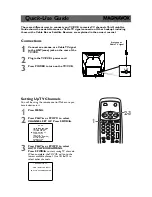
LOCATION OF USER’S CONTROL ........................................................................................................ 7
»
DISASSEMBLY AND REASSEMBLY ...................................................................................................... 9
»
INSTALLATION AND SERVICE INSTRUCTIONS ................................................................................. 12
»
PRECAUTIONS IN REASSEMBLING ................................................................................................... 17
»
FUNCTION OF MAJOR MECHANICAL PARTS .................................................................................... 18
»
ADJUSTMENT, REPLACEMENT AND ASSEMBLY OF MECHANICAL UNITS ................................... 20
»
ADJUSTMENT OF THE VCR ELECTRICAL CIRCUITRY .................................................................... 40
»
TROUBLESHOOTING ........................................................................................................................... 43
»
CHASSIS LAYOUT ................................................................................................................................ 56
»
BLOCK DIAGRAM OF TV SECTION ..................................................................................................... 58
»
BLOCK DIAGRAM OF VCR SECTION ................................................................................................. 60
»
OVERALL SCHEMATIC DIAGRAM ....................................................................................................... 70
»
DESCRIPTION OF SCHEMATIC DIAGRAM ......................................................................................... 72
»
PRINTED WIRING BOARD ASSEMBLIES ........................................................................................... 84
»
REPLACEMENT PARTS LIST ............................................................................................................... 88
»
PACKING OF THE SET ....................................................................................................................... 105
In the interests of user-safety (Required by safety regulations in some countries ) the set should be restored to its
original condition and only parts identical to those specified should be used.
S29D413VTL200
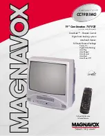
MODEL
TV/VCR COMBINATION
Chassis No. B97B
SHARP CORPORATION
This document has been published to be used for
after sales service only.
The contents are subject to change without notice.
13VT-L200
Summary of Contents for 13VT-CL10
Page 7: ...7 13VT L200 Description Of Controls FRONT LOCATION OF USER S CONTROL REAR ...
Page 56: ...56 13VT L200 8 7 10 9 6 5 4 3 2 1 A B C D E F G H CHASSIS LAYOUT PWB B PWB D PWB C ...
Page 57: ...57 13VT L200 17 16 19 18 15 14 13 12 11 10 PWB A ...
Page 58: ...58 13VT L200 8 7 10 9 6 5 4 3 2 1 A B C D E F G H BLOCK DIAGRAM OF TV SECTION ...
Page 59: ...59 13VT L200 17 16 19 18 15 14 13 12 11 10 ...
Page 61: ...61 13VT L200 17 16 19 18 15 14 13 12 11 10 ...
Page 63: ...63 13VT L200 17 16 19 18 15 14 13 12 11 10 ...
Page 67: ...67 13VT L200 17 16 19 18 15 14 13 12 11 10 ...
Page 69: ...69 13VT L200 17 16 19 18 15 14 13 12 11 10 ...
Page 70: ...70 13VT L200 8 7 10 9 6 5 4 3 2 1 A B C D E F G H OVERALL SCHEMATIC DIAGRAM ...
Page 71: ...71 13VT L200 17 16 19 18 15 14 13 12 11 10 ...
Page 74: ...74 13VT L200 8 7 10 9 6 5 4 3 2 1 A B C D E F G H SCHEMATIC DIAGRAM MAIN 1 Unit TV Section ...
Page 75: ...75 13VT L200 17 16 19 18 15 14 13 12 11 10 ...
Page 76: ...76 13VT L200 8 7 10 9 6 5 4 3 2 1 A B C D E F G H SCHEMATIC DIAGRAM MAIN 2 Unit TV Section ...
Page 77: ...77 13VT L200 17 16 19 18 15 14 13 12 11 10 ...
Page 78: ...78 13VT L200 8 7 10 9 6 5 4 3 2 1 A B C D E F G H SCHEMATIC DIAGRAM POWER Unit TV Section ...
Page 79: ...79 13VT L200 17 16 19 18 15 14 13 12 11 10 ...
Page 80: ...80 13VT L200 8 7 10 9 6 5 4 3 2 1 A B C D E F G H SCHEMATIC DIAGRAM MAIN Unit VCR 1 Section ...
Page 81: ...81 13VT L200 17 16 19 18 15 14 13 12 11 10 ...
Page 82: ...82 13VT L200 8 7 10 9 6 5 4 3 2 1 A B C D E F G H SCHEMATIC DIAGRAM MAIN Unit VCR 2 Section ...