background image

13VT-K100/150
13VT-CK10

1

SERVICE MANUAL

CONTENTS

Page

»

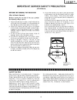
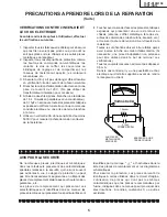
IMPORTANT SERVICE SAFETY PRECAUTION .................................................................................... 2

»

ELECTRICAL SPECIFICATIONS ............................................................................................................ 6

»

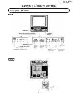
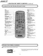
LOCATION OF USER’S CONTROL ........................................................................................................ 7

»

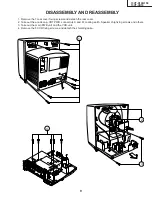
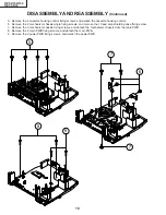
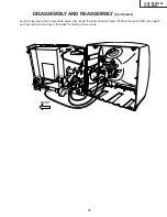
DISASSEMBLY AND REASSEMBLY ...................................................................................................... 9

»

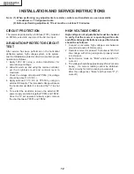
INSTALLATION AND SERVICE INSTRUCTIONS ................................................................................. 12

»

PRECAUTIONS IN REASSEMBLING ................................................................................................... 17

»

FUNCTION OF MAJOR MECHANICAL PARTS .................................................................................... 18

»

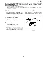
ADJUSTMENT, REPLACEMENT AND ASSEMBLY OF MECHANICAL UNITS ................................... 20

»

ADJUSTMENT OF THE VCR ELECTRICAL CIRCUITRY ..................................................................... 40

»

TROUBLESHOOTING ........................................................................................................................... 42

»

CHASSIS LAYOUT ................................................................................................................................ 55

»

BLOCK DIAGRAM OF TV SECTION ..................................................................................................... 57

»

BLOCK DIAGRAM OF VCR SECTION ................................................................................................. 59

»

OVERALL SCHEMATIC DIAGRAM ....................................................................................................... 69

»

DESCRIPTION OF SCHEMATIC DIAGRAM ......................................................................................... 71

»

PRINTED WIRING BOARD ASSEMBLIES ........................................................................................... 83

»

REPLACEMENT PARTS LIST ............................................................................................................... 89

»

PACKING OF THE SET ....................................................................................................................... 108

In the interests of user-safety (Required by safety regulations in some countries ) the set should be restored to its
original condition and only parts identical to those specified should be used.

S48O413VT-K10

MODELS

13VT-K100/150
13VT-CK10

TV/VCR COMBINATION

Chassis No. B97B

SHARP CORPORATION

This document has been published to be used for
after sales service only.
The contents are subject to change without notice.

Summary of Contents for 13VT-CK10

Page 1: ... 55 BLOCK DIAGRAM OF TV SECTION 57 BLOCK DIAGRAM OF VCR SECTION 59 OVERALL SCHEMATIC DIAGRAM 69 DESCRIPTION OF SCHEMATIC DIAGRAM 71 PRINTED WIRING BOARD ASSEMBLIES 83 REPLACEMENT PARTS LIST 89 PACKING OF THE SET 108 In the interests of user safety Required by safety regulations in some countries the set should be restored to its original condition and only parts identical to those specified should...

Page 2: ...ower receptacle when servicing this chassis X RADIATION AND HIGH VOLTAGE LIMITS 1 Be sure all service personnel are aware of the procedures and instructions covering X radiation The only potential source of X ray in current solid state TV receivers is the picture tube However the picture tube does not emit measurable X Ray radiation if the high voltage is as specified in the High Voltage Check ins...

Page 3: ...er Plug the AC cord directly into a 120 volt AC outlet Do not use an isolation transformer for this test Using to clip leads connect a 1 5k ohm 10 watt resistor paralleled by a 0 15µF capacitor in series with all exposed metal cabinet parts and a known earth ground such as electrical conduit or electrical ground connected to earth ground Use an AC voltmeter having with 5000 ohm per volt or higher ...

Page 4: ...autre que celui spécifié et ne pas effectuer de modifications déconseillées du circuit à haute tension 6 Lors de la recherche des pannes et des mesures d essai sur un récepteur qui présente une haute tension excessive éviter de s approcher inutilement du récepteur Ne pas faire fonctionner le récepteur plus longtemps que nécessaire pour localiser la cause de la tension excessive AVERTISSEMENT 1 N e...

Page 5: ...ur haute tension puissance etc Les pièces de remplacement qui présentent ces caractéristiques sont identifiées dans ce manuel les pièces électriques qui présentent ces particularités sont PRECAUTIONS A PRENDRE LORS DE LA REPARATION Suite 1 Inspecter tous les faisceaux de câbles pour s assurer que les fils ne soient pas pincés ou qu un outil ne soit pas placé entre le châssis et les autres pièces m...

Page 6: ...T IMPEDANCE 75 ohm unbalanced TUNING RANGES VHF Channels 2 thru 13 UHF Channels 14 thru 69 CATV Channels 1 14 thru 125 EIA Channel Plan VCR SECTION Format VHS Standard Video Recording System Rotary Two Head Helical Scanning Number of Video Heads 2 pcs Video Signal Standard NTSC Color System Tape Width 12 7mm 1 2inch Tape Speed SP 33 35mm sec 1 31 i p s LP 16 67mm sec 0 66 i p s Play back only EP 1...

Page 7: ...13VT K100 150 13VT CK10 7 Description Of Controls FRONT LOCATION OF USER S CONTROL REAR ...

Page 8: ... USER S CONTROL Continued Remote Control Battery Installation Before using the television prepare the Remote Control Battery Cover Pull Up Remote the battery cover as shown and insert two batteries size AA making sure the polarity matches the and marks inside the battery conpartment ...

Page 9: ...etach the rear cover 2 Take out the anode cap CRT PWB connectors K and M coating earth Speaker chip fixing screws and others 3 Take out the main PWB unit and the VCR unit 4 Remove the 5 VCR fixing screws and detach the shielding case DISASSEMBLY AND REASSEMBLY 1 4 3 2 K M ...

Page 10: ...ssis angle fixing screws and remove the 1 head amp shielding case fixing screw 7 Remove the 3 mechanism chassis fixing screws and detach the mechanism chassis from the main PWB 8 Remove the 2 main PWB fixing screws and detach the main PWB 9 Remove the 2 power PWB fixing screws and detach the power PWB DISASSEMBLY AND REASSEMBLY Continued 7 7 6 8 9 5 ...

Page 11: ...ND REASSEMBLY Continued For servicing any of the components inside disconnect the lead dressing holder Position the main PWB unit upright as shown below and connect the leads for starting the services GC YC M K S YC FRONT SP PO PG PG S GC PO ...

Page 12: ...circuitry for malfunctioning components After the voltage test Mute and bus data 0 Y mute off CIRCUIT PROTECTION The receiver is protected by a 4 0A fuse F701 mounted on PWB A wired into one side of the AC line input X RADIATION PROTECTOR CIRCUIT TEST After service has been performed on the horizontal deflection system high voltage system or B system test the X Radiation protector circuit to ascer...

Page 13: ...utton on the remote controller or at the set Table A Select the item you wish to adjust 3 Data number selection Press the volume up or down button to adjust the data number in the upper right hand side of the screen PICTURE 16 2 Figure A The K series SHARP TV VCR COMBINATION have most of the analog setup adjustments eliminated Coil and variable resistor adjustments are now performed digitally by u...

Page 14: ...SS 7 0 13 VERTICAL PHASE 0 0 7 H PHASE 20 0 31 RF AGC 18 0 63 V AMP 32 0 63 PIF VCO 40 0 127 R CUT OFF 0 0 255 G CUT OFF 0 0 255 B CUT OFF 0 0 255 G GAIN 128 0 255 B GAIN 128 0 255 Y MUTE 0 0 2 0 Normal raster 1 no Y 2 No Vertical BALANCE 32 0 63 TEXT BOX 15 0 127 TEXT PICTURE 20 0 80 CCD LEVEL 7 0 10 OPTION 1 0 3 Data is stored in IC2101 The adjustment is needed to compensate for characteristics ...

Page 15: ... normal whites at low brightness level 7 Select service adjustment item MUTE and reset data to 0 Select service adjustment item COLOR and reset data to obtain normal color level White Balance Adjustment 1 Have unit receive a good local channel 2 Enter the service mode Select service adjustment item COLOR and set to 0 minimum color COLOR does not have to be adjusted if you selected a B W picture or...

Page 16: ...ontal Position Adjustment 1 Have unit receive a good local channel 2 Enter the service mode and select service adjustment item H PHASE 3 Adjust H PHASE data value so that picture is centered Caption Position Adjustment Horizontal 1 Have unit receive a good local channel 2 Enter the service mode and select service adjustment item TEXT BOX 3 A black text box appears on the screen See Figure B below ...

Page 17: ...outer edges should not damage any parts nearby Tighten up the two screws one for fixing the mechanism and the head amplifier shield the other on the main PWB s soldering side and located near the loading motor to fix the mechanism and main PWB Reconnect the FFC cables MH and AA ME and AD Drum Unit and AH between the mechanism and main PWB Parts to pay attention to Start and end sensors Q7703 Q7704...

Page 18: ...13 Reverse guide lever ass y Pulls out the tape and controls the tape drive train height with the upper and lower guides 16 Pinch roller lever ass y Press fits the tape to the capstan during tape running 18 Loading motor A motive power which drives the mechanism It transmits the power to the master cam and cas sette housing control ass y Full Erase Head Supply Pole Base Ass y Supply Reel Disk Sup ...

Page 19: ... guide roller via the loading gear T and applies the tape around the drum assembly as well as transmits the power to the loading gears 1 Slow brake Gets in contact with the capstan D D motor linking to the master cam in the slow still mode and brakes it to a certain degree 3 Capstan D D motor A motive power which runs the tape It transmits the power via the Drive belt 4 Drive belt Transmits the po...

Page 20: ... guide height adjustment Hex Wrench 1 5 mm JiGHW0015 AE This Jig is used with the tension gauge Rotarytransformerclearance adjusting jig There are two gauges used for the tension measurements 300 g and 2 0kg Hex Wrench 1 2 mm JiGHW0012 AE 4 Torque Driver JiGTD1200 CB ADJUSTMENT REPLACEMENT AND ASSEMBLY OF MECHANICAL UNITS The explanation given below relates to the on site general service field ser...

Page 21: ...pes are especially used for electrical fine adjustment VROBBZGS CB 7k 30µm This Jig is used for height adjustment of the reverse guide Guide roller height adjustment drive 10 Alignment Tape X value adjustment gear type screw driver Reverse Guide Height Adjusting Jig 525 Monoscope Video Audio Hi Fi Audio Track 525 Monoscope 7k 58µm NTSC Color Bar 1k 58µm 13 JiGRVGH F18 BU For X value adjustment ...

Page 22: ...er drum ass y Poor S N ratio no color Poorflatnessoftheenve lope with alignment tape Clean rubber and rubber contact area with the specified cleaning liquid Pinch roller No tape running tape slack No tape running tape slack no fast forward rewind motion Reel belt Cassette not loaded or unloaded Idler ass y Tension band ass y Screen swaying Loading Motor Limiter pulley Supply take up Main brake lev...

Page 23: ...ent of teeth of casecon drive gear and drive angle gear causes malfunction The cassette cannot be set load and ejection are repeated 3 In the case when you use the magnet screw driver never approach the magnet driver to the A C head FE head and drum 4 When installing or removing take care so that the cassette housing control and tool do not contact the guide pin or drum 5 After installing the cass...

Page 24: ...o that grease does not adhere to the brake surface Reassembly Take up reel disk 1 Clean the reel disk shaft and apply grease SC 141 to it 2 Align the phase of the reel disk to that of the reel relay gear and to install a new take up reel disk onto the shaft 3 Check the reel disk height and reassemble the take up main brake ass y Note 1 Take care so that the Tu main brake ass y is not damaged Take ...

Page 25: ... long time measurement CHECKING AND ADJUSTMENT OF TAKE UP TORQUE IN REWIND MODE Remove the cassette housing control assembly After short circuiting TP7701 and TP7702 pro vided at the left on the main PWB plug in the power cord then turn on the power Setting 1 Set a torque gauge to zero on the scale Place it on the supply reel disk 2 Press the rewind button 3 To calculate the remaining capacity slo...

Page 26: ...rd mode x3 and make sure that the winding up torque is within setting Adjustment If the playback winding up torque is not within the setting replace the limiter pulley assembly Note When the torque cassette is set put a weight 500g to prevent rise CHECKING AND ADJUSTMENT OF TAKE UP TORQUE IN VIDEO SEARCH REWIND MODE Remove the cassette housing control assembly After short circuiting TP7701 and TP7...

Page 27: ... the power cord then turn on the power Checking Press the play button to set the playback mode CCW 500g T 120 Weight to prevent float 500g Figure 1 13 Figure 1 14 Checking 1 Set a cassette tape push the REC button to place the unit in the SP record mode Now check the tension pole position 1 Detach the pinch roller from the capstan shaft Do not separate excessively Or the pinch lever and pinch doub...

Page 28: ... pole 500g Weight to prevent float 500g Cassette torque meter Tension pole adjuster adjusting range Adjust so that the delta mark of tension pole adjuster is within 90 range left right CHECKINGANDADJUSTMENTOFRECORD PLAYBACK BACK TENSION Remove the cassette housing control assembly After short circuiting TP7701 and TP7702 pro vided at the left on the main PWB plug in the power cord then turn on the...

Page 29: ...thin the setting CW direction 8 8 to 23 5mN m 90 to 240gf cm CCW direction 3 9 to 9 8mN m 40 to 100gf cm Tension arm Tension spring CW CCW CW Supply reel disk Torque gauge Torque gauge CCW Take up reel disk A B Checking the brake torque at the take up side Figure 1 22 Remove the cassette housing control assembly After short circuiting TP7701 and TP7702 pro vided at the left on the main PWB plug in...

Page 30: ...20 N m 1 5 to 2 0kgf cm Figure 1 24 Solder Never touch the head 10 8mm 10 8mm A C head plate 2 Spring 1 Azimuth screw Height screw Tilt screw Figure 1 23 3 Replacement 1 Solder the removed PWB to the new head assembly 2 Adjust the height from the A C head arm lower sur face to the A C head plate to 10 8mm with slide calipers 3 places of azimuth screw section tilt screw section and A C head front s...

Page 31: ...ight adjustment box driver JiGDRiVER 11055 13 38mm Box driver Height adjusting nut CCW Reverse guide height adjusting jig Reverse guide height adjusting jig Reverse guide Mechanism chassis A C HEAD HEIGHT ROUGH ADJUSTMENT Setting 1 Set the cassette tape in the unit 2 Press the PLAY button to put the unit in the playback mode 3 Roughly adjust the height of the A C head by turning the height screw u...

Page 32: ...move the tape crease at the fixing guide flange Play back the tape and check for tape crease at the fixing guide flange 1 If there is no tape crease Turn the tilt screw clockwise so that tape crease appears once at the flange and then return the tilt screw so that the crease disappears 2 If there is tape crease Turn counterclockwise the tilt screw so that the tape crease disappears Reference If th...

Page 33: ...ve the helical lead The take up side guide roller is then rotated in the clockwise direction to flatten the envelope Figure 1 35 4 A C head X value adjustment 1 Tentatively fix A C head arm screws 1 and 2 by the method described in Page 30 Replacement 3 2 After shortcircuiting TP7701 and TP7702 plug in the powercord thenturnonthepower Andplaybackthe alignment tape VROBBZGS As a result the auto tra...

Page 34: ...EIGHT ADJUSTMENT OF REVERSE GUIDE Capstan D D motor Capstan D D motor control PWB 2 1 Reel belt REPLACEMENT OF DRUM D D MOTOR 1 Set the eject mode 2 Withdraw the main power plug from the socket Removal Perform in numerical order 1 Disconnect the FFC cable 1 2 Unscrew the D D stator assembly fixing screws 2 3 Take out the D D stator assembly 3 4 Unscrew the D D rotor assembly fixing screws 4 5 Take...

Page 35: ...ing adjustment After that perform also the electrical adjustment Playback switching point adjustment X position adjustment and check 7 After replacing the drum clean the drum Figure 1 39 2 1 3 ASSEMBLING OF PHASE MATCHING MECHANISM COMPONENTS Assemble the phase matching mechanism com ponents in the following order 1 Assemble the pinch roller assembly and pinch drive cam 2 Mounting the shifter on t...

Page 36: ...inch drive lever ass y Fit the pinch drive cam so that the notch of pinch drive cam aligns with the dent of pinch drive lever assembly Fit the pinch drive cam so that the notch of pinch drive lever assembly aligns with the half round notch of chassis Turn the reverse guide lever assembly counterclockwise to the stopper 2Insert Pinch Roller Pinch Double Action Lever Ass y Figure 1 41 2 Figure 1 41 ...

Page 37: ...ding gear T Insert point 3 Insert point 2 Insert point 4 Insert point 6 Release point 3 Shaft 1 Shaft 1 Shaft 4 1 Make sure that the loading gear is at the point 1 as shown below 2 Install paying attention to 6 insertion points and 3 release points 3 For the phase matching at the insertion point 1 see the point 2 as shown below 4 Finally fix the inserts 1 and 4 Figure 1 43 Rotation point 2 Phase m...

Page 38: ...he casecon drive gear round mark with the half round notch of master cam E ring XRESJ30 06000 Master cam Fully turn clockwise Fully turn counterclockwise Figure 1 44 1 Face the wide tooth side ward Master cam Casecon drive gear 10 2 mm Round mark Half round notch 0 2 0 2 Apply grease No grease 0 2 0 2 REPLACEMENT OF LOADING MOTOR Removal Replacement 1 Remove the loading motor and install the repla...

Page 39: ... and Drive Gear R ASSEMBLY OF CASSETTE HOUSING 1 Drive Gear and R Drive angle ass y Figure 1 47 MSPRT0381AJFJ Apply grease Apply grease Apply grease LANGF9592AJFW Top surface should be free from scratches or soil Drive angle Drive gear R Frame Figure 1 48 ...

Page 40: ... mode for head switching point and to set the tracking to center See Notes below T is displayed on the TV screen 3 Press the PLAY button of remote control to make the adjustment of head switching point then the leading edge of the head switching pulse is automatically set 5 5H lines ahead of the vertical sync as shown Figure 2 1 and the adjustment data is memorezed in the E2 P ROM IC 4 Then press ...

Page 41: ... tape Test point Monitor screen Control CH TR buttons Specification No Vertical jitter Figure 2 2 1 Playback the EP Self recorded tape in the still mode 2 Using the CH TR buttons on the remote control or inside the front cover make adjustment so that the vertical jitter becomes minimum 3 Then press the STOP button to stop the tape Note The data of this adjustment is memorized to the E2 P ROM IC ...

Page 42: ...and PC 5V lines normal Check power circuit Check poor soldering Check the signal line of sys con reset all the way up to pin 42 of IC3101 Check the power key input to IC2001 and serial datas clocks between IC2001 and IC7701 Check power circuit Check the sensor inputs to IC7701 from mechanism CAM switches start end sensors and reel sensors KEY IN TROUBLESHOOTING FLOW CHART NO 1 2 Key in input for V...

Page 43: ...tape is loaded Does end sensor pulse at pin 3 of IC7701 change from L to H level when the cassette tape is loaded Does start sensor pulse at pin 2 of IC7701 change from L to H level when the cassette tape is loaded Check the start sensor and all the way up to IC7701 Check the end sensor and all the way up to IC7701 Check cam switches and all the way up to IC7701 FLOW CHART NO 1 4 NO NO NO NO NO NO...

Page 44: ...ng of PC9V and PC5V lines Are serial clock pulse and TV data pulse applied to pins 67 and 66 of IC7701 from IC2001 Are system control data pulse and system control ready pulse applied to pins 36 and 35 of IC2001 from IC7701 Check between the MC connector and IC7701 and between the MC connector and pin 75 of IC7701 CAPSTAN MOTOR TROUBLESHOOTING The capstan motor fails to run Is the voltage more tha...

Page 45: ... to run Is the voltage more than about 2 6V applied at pin 1 of ME connector Check between the ME connector and all the way up to pin 86 of IC7701 Is 5V at pin 7 of ME connector Check replace the drum motor Is 12V at pin 4 of ME connector Check the AT 5V line NO NO NO YES YES YES Check or replace IC7701 The drum motor runs only for a few seconds Check pin 76 of IC7701 Check the drum motor Are ther...

Page 46: ...of IC7701 Check the composite sync signal at pin 14 of IC2201 Q2201 and Q2202 Is there the head switching pulse at pin 18 of IC7701 Is there the drum FG signal at pin 87 of IC7701 Is there the drum control output at pin 78 of IC7701 Check the signal line between pin 7 of AD and pin 76 of IC7701 Check PG and FG to pins 5 and 3 of the connector ME and the drum motor Is there the drum control voltage...

Page 47: ... pin 14 of IC2201 Q2201 and Q2202 up to pin 84 of IC7701 Replace IC7701 Replace A C head Check A Check B In case of NO GOOD Does there appear the V sync at pin 84 at IC7701 Is there REC CTL signal output at pins 92 91 of IC7701 Is there capstan control signal at pin 77 of IC7701 Are REC and or PB mode inoperative Is the FFC AA MH normal Does the A C head operate normally Adjust the height of the A...

Page 48: ...tween pin 25 of IC2201 and pin 14 of IC402 FLOW CHART NO 1 13 NO NO NO NO NO NO NO YES YES YES YES YES YES YES YES RECORDING MODE TROUBLESHOOTING Recording LUMINANCE is not possible Recording is possible but without color Is there a signal at pin 29 of IC2201 Is there a signal at pin 57 of IC2201 Check parts around and pins 27 38 36 and 29 of IC2201 Check parts around pins 30 and 31 of IC2201 Is t...

Page 49: ...f IC3301 Is there a signal at pin 57 of IC2201 Is there a signal at pin 27 of IC2201 Is there a signal at pin 25 of IC2201 Check between pin 25 of IC2201 and all the way up thru pin 14 of IC402 Check peripheral circuits of X5502 Check between pin 30 of IC3301 and all the way up thrn to pin 57 of IC2201 Check the I 2 C bus data and clock at pins 8 and 7 of IC2201 Is there a signal at pin 12 of IC22...

Page 50: ...ce IC2201 Check the I 2 C bus data and clock signal line Replace IC2201 Is there a signal at pin 87 or 91 of IC2201 Is the supply voltage of 5V feed to pin 84 of IC2201 Is there a signal at pin 85 of IC2201 Check between pin 85 of IC2201 and pin 1 of IC402 Is voltage of pins 86 and 88 of IC2201 normal Is there H level at pin 70 of IC2201 Check BIAS CTL H line Check PC 9V line Is there a signal at ...

Page 51: ... Is there a signal at pin 85 of IC2201 Check BIAS CTL H line Replace defective parts Readjust azimuth and height Replace A C head Check AUDIO MUTE H line Replace IC2201 Is there L level at pin 70 of IC2201 Are azimuth and height of the A C head properly adjusted Check line between pin 85 of IC2201 pin 1 of IC402 Are the FFC MH AA and the PB AMP s peripheral parts around pins 75 78 of IC2201 normal...

Page 52: ...ck D701 thru D704 L701 and R701 Is AC cord connected Is 170V DC applied to C705 Check T701 and adjacent parts Is 16V DC applied to pin 4 of IC701 Check IC701 R717 Check IC701 and adjacent parts CRT connector GC1 GC5 bias check The Fuse is again blown out D701 D702 D703 D704 D705 Connect AC cord F701 Check Normal Normal IC701 Check Normal Abnomal IC401 iX2933CE Normal Normal C854 Blown out Replace ...

Page 53: ...Check the IC401 and adjacent parts Check IC2001 Check the tuner AGC Check the IC351 Does the noise level increase at max Contrast Brightness and Sound Control Is there a signal at pin 43 of IC401 Noise increases but no signal is received Is there a signal at pin 41 of IC401 Picture noise decrease but sound level varies greatly Check the tuner bias Normal Abnormal Abnormal Check IC401 Normal Check ...

Page 54: ...the 5V and GND lines Check key input terminals Replace the infrared remote control as required Check pin 10 of IC2001 and or receiver Reposition the set not to be exposed to strong light Is L pulse given out of pin 1 of the receiver and received at pin 10 of IC2001 when the infrared remote control is activated No operation is possible from the infrared remote control Does waveform appear at pin 8 ...

Page 55: ...13VT K100 150 13VT CK10 13VT K100 150 13VT CK10 H G F E D C B A 1 2 3 4 5 6 7 8 9 10 11 12 55 56 CHASSIS LAYOUT PWB A PWB C PWB B PWB D ...

Page 56: ...13VT K100 150 13VT CK10 13VT K100 150 13VT CK10 H G F E D C B A 1 2 3 4 5 6 7 8 9 10 11 12 57 58 BLOCK DIAGRAM OF TV SECTION ...

Page 57: ...13VT K100 150 13VT CK10 13VT K100 150 13VT CK10 H G F E D C B A 1 2 3 4 5 6 7 8 9 10 11 12 59 60 BLOCK DIAGRAM OF VCR SECTION OVERALL BLOCK DIAGRAM ...

Page 58: ...13VT K100 150 13VT CK10 13VT K100 150 13VT CK10 H G F E D C B A 1 2 3 4 5 6 7 8 9 10 11 12 61 62 BLOCK DIAGRAM OF VCR SECTION SERVO PROCESS BLOCK DIAGRAM ...

Page 59: ...13VT K100 150 13VT CK10 13VT K100 150 13VT CK10 H G F E D C B A 1 2 3 4 5 6 7 8 9 10 11 12 63 64 BLOCK DIAGRAM OF VCR SECTION SYSTEM CONTROL BLOCK DIAGRAM SAFETY DEVICE BLOCK DIAGRAM ...

Page 60: ...13VT K100 150 13VT CK10 13VT K100 150 13VT CK10 H G F E D C B A 1 2 3 4 5 6 7 8 9 10 11 12 65 66 BLOCK DIAGRAM OF VCR SECTION VIDEO SIGNAL FLOW BLOCK DIAGRAM ...

Page 61: ...13VT K100 150 13VT CK10 13VT K100 150 13VT CK10 H G F E D C B A 1 2 3 4 5 6 7 8 9 10 11 12 67 68 BLOCK DIAGRAM OF VCR SECTION AUDIO BLOCK DIAGRAM ...

Page 62: ...13VT K100 150 13VT CK10 13VT K100 150 13VT CK10 H G F E D C B A 1 2 3 4 5 6 7 8 9 10 11 12 69 70 OVERALL SCHEMATIC DIAGRAM ...

Page 63: ...erwise indicated 2 All voltages measured with 1000µV B W or Color signal WAVEFORM MEASUREMENT CONDI TIONS 1 Photographs taken on a standard gated color bar signal the tint setting adjusted for proper color The wave shapes at the red green and blue cathodes of the picture tube depend on the tint color level and picture control 2 indicates waveform check points See chart waveforms are measured from ...

Page 64: ...13VT K100 150 13VT CK10 13VT K100 150 13VT CK10 H G F E D C B A 1 2 3 4 5 6 7 8 9 10 11 12 73 74 SCHEMATIC DIAGRAM MAIN 1 Unit TV Section ...

Page 65: ...13VT K100 150 13VT CK10 13VT K100 150 13VT CK10 H G F E D C B A 1 2 3 4 5 6 7 8 9 10 11 12 75 76 SCHEMATIC DIAGRAM MAIN 2 Unit TV Section ...

Page 66: ...13VT K100 150 13VT CK10 13VT K100 150 13VT CK10 H G F E D C B A 1 2 3 4 5 6 7 8 9 10 11 12 77 78 SCHEMATIC DIAGRAM POWER Unit TV Section ...

Page 67: ...13VT K100 150 13VT CK10 13VT K100 150 13VT CK10 H G F E D C B A 1 2 3 4 5 6 7 8 9 10 11 12 79 80 SCHEMATIC DIAGRAM MAIN Unit VCR 1 Section DTC124ES ...

Page 68: ...13VT K100 150 13VT CK10 13VT K100 150 13VT CK10 H G F E D C B A 1 2 3 4 5 6 7 8 9 10 11 12 81 82 SCHEMATIC DIAGRAM MAIN Unit VCR 2 Section ...

Page 69: ...00 150 13VT CK10 13VT K100 150 13VT CK10 H G F E D C B A 1 2 3 4 5 6 7 8 9 10 11 12 83 84 PRINTED WIRING BOARD ASSEMBLIES PWB B CRT Unit Wiring Side PWB D FRONT AV Unit Wiring Side PWB C POWER Unit Wiring Side ...

Page 70: ...13VT K100 150 13VT CK10 13VT K100 150 13VT CK10 H G F E D C B A 1 2 3 4 5 6 7 8 9 10 11 12 85 86 PWB A MAIN Unit Wiring Side ...

Page 71: ...13VT K100 150 13VT CK10 13VT K100 150 13VT CK10 H G F E D C B A 1 2 3 4 5 6 7 8 9 10 11 12 87 88 PWB A MAIN Unit Chip Parts Side ...

Page 72: ... Q AA Q2207 VS2SA1037KQ 1 J 2SA1037K Q AA Q2208 VS2SC2412KQ 1 J 2SC2412K Q AA Q2209 VS2SC2412KQ 1 J 2SC2412K Q AA Q2210 VS2SC2412KQ 1 J 2SC2412K Q AA Q2215 VS2SC2412KQ 1 J 2SC2412K Q AA Q2217 VS2SC2412KQ 1 J 2SC2412K Q AA Q2218 VSUN2113 1 J UN2113 AA Q2219 VSUN2213 1 J UN2113 AA Q2220 VS2SA1037KQ 1 J 2SA1037K Q AA Q2224 VSUN2113 1 J UN2113 AA Q2227 VSUN2213 1 J UN2113 AA Q2228 VSUN2213 1 J UN2113 ...

Page 73: ...ramic AA C343 VCCCCY1HH151J J 150p 50V Ceramic AA C351 VCKYCY1HB272K J 2700p 50V Ceramic AA C352 VCEAEA1CW107M J 100 16V EL AC C354 VCEA0A1CW477M J 470 16V EL AC C355 VCEA0A1CW226M J 22 16V EL AB C356 VCQYTA1HM104K J 0 1 50V Mylar AC C357 VCKYCY1CF474Z J 0 47 16V Ceramic AB C360 VCKYCY1HF103Z J 0 01 50V Ceramic AA C361 VCEA0A1CW337M J 330 16V EL AC C401 VCCCCY1HH271J J 270p 50V Ceramic AA C402 VCC...

Page 74: ... J 220p 50V Ceramic AA C3103 VCEAKA1HW105M J 1 50V EL AB C3104 VCKYCY1HB102K J 1000p 50V Ceramic AA C3105 VCCCCY1HH221J J 220p 50V Ceramic AA C3107 VCKYCY1HF103Z J 0 01 50V Ceramic AA C3108 VCEAKA0JW107M J 100 6 3V EL AB C3109 VCKYCY1CB104K J 0 1 16V Ceramic AB C3110 VCKYCY1HB222K J 2200p 50V Ceramic AA C3111 VCEAKA0JW107M J 100 6 3V EL AB C3112 VCKYPA1HF103Z J 0 01 50V Ceramic AA C3113 VCCCCY1HH1...

Page 75: ...J 1000p 50V Ceramic AA RESISTORS M Ox Metal Oxide RJ1 VRN MD2AL000J J 0 0 1W Metal Film AA RJ2 VRN MD2AL000J J 0 0 1W Metal Film AA RJ3 VRN MD2AL000J J 0 0 1W Metal Film AA RJ7 VRN MD2AL000J J 0 0 1W Metal Film AA RJ8 VRN MD2AL000J J 0 0 1W Metal Film AA RJ9 VRN MD2AL000J J 0 0 1W Metal Film AA RJ10 VRN MD2AL000J J 0 0 1W Metal Film AA RJ11 VRN MD2AL000J J 0 0 1W Metal Film AA RJ12 VRN MD2AL000J J...

Page 76: ...R452 VRN MD2AL000J J 0 0 1W Metal Film AA R453 VRD RA2EE474J J 470k 1 4W Carbon AA R454 VRD RA2EE184J J 180k 1 4W Carbon AA R456 VRN MD2AL273J J 27k 0 1W Metal Film AA R466 VRN VV3AB1R5J J 1 5 1W Metal Film AA R501 VRN MD2AL101J J 100 0 1W Metal Film AA R504 VRD RA2BE471J J 470 1 8W Carbon AA R505 VRD RA2BE101J J 100 1 8W Carbon AB R506 VRD RA2BE683G J 68k 1 8W Carbon AA R507 VRD RA2BE104G J 100k ...

Page 77: ... 0 1W Metal Film AA R3108 VRN MD2AL102J J 1k 0 1W Metal Film AA R3109 VRD RA2BE152J J 1 5k 1 8W Carbon AA R3110 VRN MD2AL102J J 1k 0 1W Metal Film AA R3111 VRN MD2AL103J J 10k 0 1W Metal Film AA R3112 VRN MD2AL102J J 1k 0 1W Metal Film AA R3113 VRN MD2AL103J J 10k 0 1W Metal Film AA R3117 VRD RA2BE102J J 1k 1 8W Carbon AA R3118 VRN MD2AL122J J 1 2k 0 1W Metal Film AA R3119 VRS CY1JF105J J 1M 1 16W...

Page 78: ...VRN MD2AL562J J 5 6k 0 1W Metal Film AA R7740 VRN MD2AL103J J 10k 0 1W Metal Film AA R7743 VRD RA2BE103J J 10k 1 8W Carbon AA R7744 VRD RA2BE103J J 10k 1 8W Carbon AA R7745 VRD RA2BE103J J 10k 1 8W Carbon AA R7746 VRD RA2BE102J J 1k 1 8W Carbon AA R7747 VRD RA2BE102J J 1k 1 8W Carbon AA R7748 VRD RA2BE102J J 1k 1 8W Carbon AA R7749 VRD RA2BE102J J 1k 1 8W Carbon AA R7750 VRD RA2BE102J J 1k 1 8W Ca...

Page 79: ... Fuse 4A AC FB2001 RBLN 0037CEZZ J Ferrite Bead AB FB7701 RBLN 0036CEZZ J Ferrite Bead AB FB7702 RBLN 0036CEZZ J Ferrite Bead AB FH701 QFSHD1013CEZZ J Fuse Holder AC FH702 QFSHD1014CEZZ J Fuse Holder AC P350 QPLGN0361CEZZ J Plug 3 pin OR AB P401 QPLGZ0840CEZZ J Plug 8 pin MA AF P402 QPLGZ1040CEZZ J Plug 10 pin MB AE P404 QPLGN0561CEZZ J Plug 5 pin GC AB P602 QPLGN0603CEZZ J Plug 6 pin K AB P651 QP...

Page 80: ...EZZ J 0 0033 2kV Ceramic AE C708 VCCSPA1HL471J J 470p 50V Ceramic AA C709 VCEA0A1HW107M J 100 50V EL AB C710 VCQYTA1HM222J J 2200p 50V Mylar AA C711 VCFYFA1HA224J J 0 22 50V Mylar AB å C712 RC KZ0312CEZZ J 0 0047 50V Ceramic AD C722 VCKYPA1HB102K J 1000p 50V Ceramic AA C723 VCKYPA1HB102K J 1000p 50V Ceramic AA C724 VCKYPA1HB102K J 1000p 50V Ceramic AA C725 VCKYPA1HB102K J 1000p 50V Ceramic AA C726...

Page 81: ...PEZZ R Screw AB HM706 LX GZ3001PEZZ R Screw AB HM707 LX GZ3001PEZZ R Screw AB HM708 LX GZ3001PEZZ R Screw AB HM709 LX GZ3001PEZZ R Screw AB HM710 LX GZ3001PEZZ R Screw AB QCNW 2211PEZZ R Connecting Cord AD QCNW 6008PEN3 R Connecting Cord PG AE LX BZ3049GEFD J Screw AA LX BZ3100CEFD J Screw AA PWB C DUNTK9490WEV2 POWER Unit Continued PWB B DUNTK8606WEV4 CRT Unit TRANSISTORS Q852 VS2SC2229O 1E J 2SC...

Page 82: ...0AJZZ V Worm Gear AD 45 NGERW1066AJZZ V Worm Wheel Gear AD 46 NiDR 0018AJZZ V Idler Wheel Ass y AK 47 NPLYV0162AJZZ V Motor Pully AD 48 NPLYV0163AJZZ V Limitter Pulley Ass y AM 49 NROLP0131GEZZ J Guide Roller AL 50 NSFTP0032AJZZ V Tension Pole Adjuster AB 51 MSPRC0217AJFJ V Guide Roller Spring AC 52 PREFL1011AJZZ V Light Guide AE 53 QCNW 0247AJZZ V FFC for Drum Motor AG MECHANISM CHASSIS 55 QCNW 0...

Page 83: ... 6 MECHANISM CHASSIS PARTS 22 31 12 20 18 214 19 29 49 51 8 11 203 49 51 7 58 52 4 25 24 2 33 15 1 50 218 207 67 207 63 62 66 66 66 53 65 216 41 61 21 38 17 208 60 47 44 6 30 36 9 39 45 219 10 30 40 27 43 46 43 35 35 37 34 23 62 48 209 210 211 212 213 223 5 26 32 68 69 55 16 202 222 221 201 202 202 220 59 70 57 71 56 ...

Page 84: ...LDX1031AJZZ V Holder R AE 306 MLEVF0469AJFW V Proof Lever R AE 307 MLEVP0281AJ00 V Door Open Lever AD 308 MSLiF0075AJFW V Slider AK 309 MSPRD0151AJFJ V Proof Lever R Spring AB 310 MSPRD0166AJFJ V Drive Gear R Spring AE 311 MSPRP0175AJFJ V Cassette Spring AE 312 MSPRT0381AJFJ V Double Action Spring AC 313 NGERH1278AJZZ V Drive Gear L AE 314 NGERH1279AJZZ V Drive Gear R AE 315 NGERR1008AJ00 V Double...

Page 85: ...o Description Code Ref No Part No Description Code 103 13VT K100 150 13VT CK10 H G F E D C B A 1 2 3 4 5 6 CHASSETTE HOUSING CONTROL PARTS 301 300 304 311 308 311 305 306 309 303 312 316 315 307 314 310 317 313 302 ...

Page 86: ...EKA R Rear Cabinet 13VT CK10 BB 3 QACCD3051CESA J AC Cord AK 13VT K100 CK10 3 QACCD3055CESB J AC Cord 13VT K150 AK 4 QCNW 2206PEZZ R Connecting Cord AD 5 VSP9050PB15WA J Speaker AN 6 PSLDM0250PEFW R Shield AD 7 PSLDM0248PEFW R Top Shield AN 8 PSLDM0249PEFW R Bottom Shield AG 9 LANGT0038PEFW R Fixing Metal AC 10 QEARC1404PEZZ R Coating Earth AD 11 LCHSM0072PEKZ R Chassis Frame AQ 12 MSPRT0001PEFJ R...

Page 87: ... 11 12 105 106 CABINET AND MECHANICAL PARTS 1 10 1 12 1 6 1 3 1 1 5 14 30 1 9 1 2 4 24 28 15 11 13 24 3 25 40 7 26 20 22 9 22 33 41 36 35 6 12 10 16 1 1 11 1 13 1 14 1 4 1 9 22 32 21 27 8 31 20 28 17 34 24 2 23 26 PWB D PWB A 19 PWB B 22 16 25 25 42 43 1 8 1 8 1 5 38 39 PWB C 26 24 1 7 ...

Page 88: ... R C Unit AV 13VT K100 13VT CK10 RRMCG1330PESB R Infrared R C Unit AV 13VT K150 SUPPLIED ACCESORIES PACKING PARTS NOT REPLACEMENT ITEM SPAKC6317PEZZ Packing Case 13VT K100 SPAKC6318PEZZ Packing Case 13VT K150 SPAKC6338PEZZ Packing Case 13VT CK10 SSAKA0031PEZZ Polyethylene Sack SPAKP0095PEZZ Polyethylene Sack SPAKX2671PEZZ Buffer Material TLABR7005PEZZ UPC Label 13VT CK10 TLABN0001PEZZ Serial Numbe...

Page 89: ...13VT K100 150 13VT CK10 109 Memo ...

Page 90: ...duced stored in a retrieval system or transmitted in any form or by any means electronic mechanical photocopying recording or otherwise without prior written permission of the publisher TQ0425 S Apr 1998 Printed in Japan YO KG SHARP CORPORATION AV Systems Group Quality Reliability Control Center Yaita Tochigi 329 2193 Japan ...

Reviews: