background image

1

13K-M100/150
CK13M10/15

SERVICE MANUAL

Page

æ

ELECTRICAL SPECIFICATIONS ........................................................................................... 1

æ

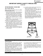
IMPORTANT SERVICE SAFETY PRECAUTION ................................................................... 2

æ

LOCATION OF USER'S CONTROL ....................................................................................... 6

æ

INSTALLATION AND SERVICE INSTRUCTIONS .................................................................. 7

æ

CHASSIS LAYOUT ............................................................................................................... 13

æ

BLOCK DIAGRAM ................................................................................................................ 14

æ

DESCRIPTION OF SCHEMATIC DIAGRAMS ..................................................................... 15

æ

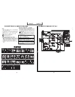
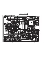
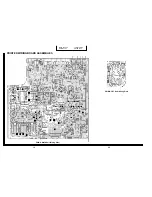
SCHEMATIC DIAGRAMS ..................................................................................................... 16

æ

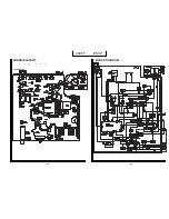
PRINTED WIRING BOARD ASSEMBLIES .......................................................................... 19

æ

REPLACEMENT PARTS LIST .............................................................................................. 23

æ

PACKING OF THE SET ........................................................................................................ 30

CONTENTS

In the interests of user-safety (Required by safety regulations in some countries ) the set should be restored to its
original condition and only parts identical to those specified should be used.

POWER INPUT ........................... 120 V  AC 60 Hz

POWER RATING .......................................... 69 W

PICTURE SIZE ..................... 580cm

2

(89.9sq inch)

CONVERGENCE .................................... Magnetic

SWEEP DEFLECTION ........................... Magnetic

FOCUS ....................... Hi-Bi-Potential Electrostatic

INTERMEDIATE FREQUENCIES

Picture IF Carrier Frequency ............. 45.75 MHz

Sound IF Carrier Frequency ............. 41.25 MHz

Color Sub-Carrier Frequency ............ 42.17 MHz

 (Nominal)

AUDIO POWER

OUTPUT RATING ........ 0.9W (at 10% distortion)

SPEAKER

SIZE ................................................ 8cm(Round)

VOICE COIL IMPEDANCE ....... 8ohm at 400 Hz

ANTENNA INPUT IMPEDANCE

VHF/UHF ............................ 75 ohm Unbalanced

TUNING RANGES

VHF-Channels ....................................... 2thru 13

UHF-Channels ..................................... 14thru 69

CATV Channels .................................... 1thru 125

USA: (EIA, Channel Plan)

ELECTRICAL SPECIFICATIONS

Specifications are subject to change without prior
notice.

13K-M100/150
CK13M10/15

COLOR TELEVISION

Chassis No. SN-80

MODELS

SHARP  CORPORATION

This document has been published to be used for

after sales service only.

The contents are subject to change without notice.

S28L513K-M100

Summary of Contents for 13K-M100

Page 1: ... PICTURE SIZE 580cm2 89 9sq inch CONVERGENCE Magnetic SWEEP DEFLECTION Magnetic FOCUS Hi Bi Potential Electrostatic INTERMEDIATE FREQUENCIES Picture IF Carrier Frequency 45 75 MHz Sound IF Carrier Frequency 41 25 MHz Color Sub Carrier Frequency 42 17 MHz Nominal AUDIO POWER OUTPUT RATING 0 9W at 10 distortion SPEAKER SIZE 8cm Round VOICE COIL IMPEDANCE 8ohm at 400 Hz ANTENNA INPUT IMPEDANCE VHF UH...

Page 2: ... WITH SAME TYPE 4A 125V FUSE 4A 125V X RADIATION AND HIGH VOLTAGE LIMITS 1 Be sure all service personnel are aware of the procedures and instructions covering X radiation The only potential source of X ray in current solid state TV receivers is the picture tube However the picture tube does not emit measurable X Ray radiation if the high voltage is as specified in the High Voltage Check instructio...

Page 3: ...characteristics are often not evident from visual inspection nor can protection afforded by them be necessarily increased by using replacement components rated for higher voltage wattage etc Replacement parts which have special safety characteristics are identified in this manual electrical components having such features are identified by å and shaded areas in the Replacement Parts Lists and Sche...

Page 4: ...ler le tube image qu en porant des lunettes incassables et qu après avoir déchargé totalement la haute tension LIMITES DES RADIATIONS X ET DE LA HAUTE TENSION 1 Tout le personnel réparateur doit être instruit des instructions et procédés relatifs aux radiations X Le tube image seule source de rayons X dons les téleviseurs transistorisés n émet pourtant pas de rayons mesurables si la haute tension ...

Page 5: ...lisant des pièces de remplacement étalonnées pour haute tension puissance etc Les pièces de remplacement qui présentent ces caractéristiques sont identifiées dans ce manuel les pièces électriques qui présentent ces particularités sont PRECAUTIONS A PRENDRE LORS DE LA REPARATION Suite 1 Inspecter tous les faisceaux de câbles pour s assurer que les fils ne soient pas pincés ou qu un outil ne soit pa...

Page 6: ...6 13K M100 150 CK13M10 15 LOCATION OF USER S CONTROL ...

Page 7: ...alfunctioning components After the voltage test make Y mute off normal mode CIRCUIT PROTECTION The receiver is protected by a 4 0A fuse F701 mounted on PWB A wired into one side of the AC line input X RADIATION PROTECTOR CIRCUIT TEST 1 After service has been performed on the horizontal deflection system high voltage system B system test the X Radiation protection circuit to ascertain proper operat...

Page 8: ...ode press the channel up or channel down button on the remote transmitter or at the set the service adjustment number will vary in increments of one from S01 to S19 Select the item you wish to adjust 3 Data number selection Press the volume up or down button to adjust the data number Figure B S01 D 00 02 For adjustments of this model the bus data is convered to various analog signals by the D A co...

Page 9: ...ITION 18 00 7F S19 Y MUTE 00 00 01 03 00 NORMAL 01 no Y 03 NO VERTICAL SERVICE NUMBER DATA ADJUSTMENT CONTENTS ADJUSTMENT ITEM RANGE Holding down both the CH UP DOWN keys on the TV set at service mode for more then 2 seconds will automatically write the above initial values into IC2101 NECESSARY UNNECESSARY ADJUSTMENT NOTES PART REPLACED IC2001 IC201 IC2101 CRT The adjustment is needed to compensa...

Page 10: ...ue to 01 this turn off the luminance signal Y mute 5 Select service adjustment S04 and adjust data value to obtain 0 17 volts on the digital voltmeter 6 Adjust the master screen cotrol untill raster darkens to the point where raster is barely seen 7 Adjust service adjustments S11 red S12 green and S13 blue to obtain a good grey scale with normal whites at low brightness level 8 Select service adju...

Page 11: ... be set 00 03 when adjust another data retrace line will be appear Horizontal position adjustment 1 Have unit receive a good local channel 2 Enter the service mode and select service adjustment S07 3 Adjust S07 data value so that picture is centered Caption position adjustment horizontal 1 Have unit receive a good local channel 2 Enter the service mode and select service adjustment S18 3 A black t...

Page 12: ...12 13K M100 150 CK13M10 15 Memo ...

Page 13: ...H G F E D C B A 1 2 3 4 5 6 H G F E D C B A 1 2 3 4 5 6 13K M100 150 CK13M10 15 13K M100 150 CK13M10 15 13 14 CHASSIS LAYOUT BLOCK DIAGRAM ...

Page 14: ...hms M 1 Meg ohm 2 All resistors are 1 8 watt unless otherwise noted 3 All capacitors are µ F unless otherwise noted P µµ F 4 G indicates 2 tolerance may be used 5 indecates line isolated ground 6 indecates hot ground VOLTAGE MEASUREMENT CONDITIONS 1 All DC voltages are measured with DVM connected between points indicated and chassis ground line voltage set at 120V AC and all controls set for norma...

Page 15: ...H G F E D C B A 1 2 3 4 5 6 7 8 9 10 11 12 13K M100 150 CK13M10 15 13K M100 150 CK13M10 15 SCHEMATIC DIAGRAM MAIN Unit 17 18 ...

Page 16: ...H G F E D C B A 1 2 3 4 5 6 7 8 9 10 11 12 13K M100 150 CK13M10 15 13K M100 150 CK13M10 15 PRINTED WIRING BOARD ASSEMBLIES PWB A MAIN Unit Wiring Side PWB B CRT Unit Wiring Side 20 19 ...

Page 17: ...H G F E D C B A 1 2 3 4 5 6 7 8 9 10 11 12 13K M100 150 CK13M10 15 13K M100 150 CK13M10 15 PWB A MAIN Unit Chip Parts Side 21 22 ...

Page 18: ...eristic as the fac tory recommended replacement parts shown in this service manual may create shock fire or other hazards HOW TO ORDER REPLACEMENT PARTS To have your order filled promptly and correctly please furnish the following informations 1 MODEL NUMBER 2 REF NO 3 PART NO 4 DESCRIPTION in USA Contact your nearest SHARP Parts Distributor to or der For location of SHARP Parts Distributor Please...

Page 19: ...A0A1HW225M J 2 2 50V EL AB C604 VCEA0A1CW227M J 220 16V EL AC çå C608 VCFPPD3CA522H J 5200p 1600V Metal Poly Film AE C609 RC QZA223TAYK J 0 022 50V Mylar AB C612 VCFPPB2EB334J J 0 33 250V Metal Poly FilmAF C631 VCEA0A1HW225M J 2 2 50V EL AB C632 VCKYCY1HF103Z J 0 01 50V Ceramic AA C633 VCEA0A1HW105M J 1 0 50V EL AB C652 VCEA0A1HW475M J 4 7 50V EL AB C653 VCEA0A1CW106M J 10 16V EL AB C661 VCKYPA2HB...

Page 20: ...W Carbon AA R208 VRN MD2AL391J J 390 0 1W Metal Film AA R301 VRD RA2BE222J J 2 2k 1 8W Carbon AA R302 VRN MD2AL102J J 1 0k 0 1W Metal Film AA R303 VRN MD2AL153J J 15k 0 1W Metal Film AA R307 VRN MD2AL333J J 33k 0 1W Metal Film AA R352 VRN MD2AL332J J 3 3k 0 1W Metal Film AA R353 VRN MD2AL4R7J J 4 7 0 1W Metal Film AA R354 VRN MD2AL152J J 1 5k 0 1W Metal Film AA R361 VRD RA2BE102J J 1 0k 1 8W Carbo...

Page 21: ... Metal Film AA R2008 VRD RA2BE224J J 220k 1 8W Carbon AA R2009 VRN MD2AL102J J 1 0k 0 1W Metal Film AA R2010 VRN MD2AL102J J 1 0k 0 1W Metal Film AA R2011 VRN MD2AL821J J 820 0 1W Metal Film AA R2012 VRN MD2AL471J J 470 0 1W Metal Film AA R2020 VRD RM2HD223J J 22k 1 2W Carbon AA R2022 VRD RA2BE333J J 33k 1 8W Carbon AA R2024 VRD RA2BE682J J 6 8k 1 8W Carbon AA R2025 VRD RA2BE682J J 6 8k 1 8W Carbo...

Page 22: ... C881 VCEA0A1CW106M J 10 16V Electrolytic AB C883 VCEA0A1CW336M J 33 16V Electrolytic AB DUNTK9529WEV0 V4 MAIN Unit Continued MISCELLANEOUS PARTS SP1 VSP0080PBK58A J Speaker AL å ACC701QACCD3038CESA AC Cord 13K M100 CK13M10 AK or QACCD3051CESA or QACCD3037CESA or QACCD3056CESA or QACCD3055CESA å ACC701QACCD3037CESB AC Cord 13K M150 CK13M15 AK or QACCD3055CESB QCNW 2105PEZZ R Connecting Cord AF QCN...

Page 23: ...X2630PEZZ _ Packing Add _ SSAKA0001PEZZ _ Polyethylene Bag _ PACKING PARTS 13K M100 1 CCABA2395WEV0 R Cabinet Ass y Front AZ 1 1 _ _ Cabinet Front 1 2 GCOVA0078PEKA R Cover AD 1 3 JBTN 0258PESA R Button AE 2 GCABB2309PEKA R Cabinet AW 13K M150 1 CCABA2395WEV2 R Cabinet Ass y Front AZ 1 1 _ _ Cabinet Front 1 2 GCOVA0078PEKA R Cover AD 1 3 JBTN 0258PESB R Button AR 2 GCABB2309PEKB R Cabinet AW CK13M...

Page 24: ... No Description Code 30 13K M100 150 CK13M10 15 REAR Use tapes to fix the packing case Packing case FRONT Buffer material Polystyrene mat Polystyrene Bag Operation manual Guarantee Card and batteries Printed in Japan TQ 0394 S PACKING OF THE SET ...

Reviews: