background image


OPERATION MANUAL 

& PARTS LIST 


Machine Model No.: 

Machine S/N.: 

1118H 


Summary of Contents for 1118H

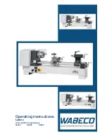
Page 1: ...OPERATION MANUAL PARTS LIST Machine Model No Machine S N 1118H ...

Page 2: ... BELT ADJUSTMENT 9 J COLLET CLOSER REMOVAL 9 K COLLET CLOSER REPLACEMENT 9 L COLLET CLOSER ADJUSTMENT 10 M CARRIAGE INDICATED RING 10 N CARRIAGE LOCK 11 O CARRIAGE CLUTCHES 11 P CROSS SLIDE INDICATING RING 11 Q QUICK ACTING TOOL POST COMPOUND SLIDE ASSEMBLY 12 R POWER FEED UNIT 13 S COOLANT FACILITIES 14 T TAILSTOCK 14 U TAILSTOCK SPINDLE LOCK 14 V TAILSTOCK BODY LOCK 14 THREAD CUTTING 15 OUTSIDE ...

Page 3: ...conomical use accuracy and minimum maintenance of the machine This manual is an introduction to the SHARP model 1118H HIGH ACCURACY TOOL ROOM LATHE It is used for installation operation and maintenance of the 1118H SHARP MACHINES Also for fast reference because it is necessary to make minor adjustments or do preventive maintenance For personnel and operators who deal with the 1118H machine FOR MOD...

Page 4: ...ide way 1118H Level adjustment process 1 Put pads C Figure B under each of six points 2 Insert the pillar A into the pedestal hole and adjust the nut B to the location according to machine level need 3 Make sure every point is touching the ground to support the machine ...

Page 5: ...oughly cleaned to remove all antirust liquid use a soft brush and solvent This is very important because it can prevent any dirt or grit which may have accumulated on the antirust liquid from working under the sliding members and causing undue wear CAUTION DO NOT USE COMPRESSED AIR TO CLEAN WHICH WILL REDUCE THE MACHINES LIFE B FOUNDATION INSTALLATION AND LEVELING A fairly flat foundation and prop...

Page 6: ... counterclockwise when viewed from the tailstock end of the machine If the spindle dose not turn in the correct direction turn Cam Switch A Figure 2 to OFF position Disconnect electric power source and interchanges any two leads until the turning direction is correct When the spindle is rotation correctly secure switch case cover turn Cam Switch A Figure 2 to ON position Please check the coolant d...

Page 7: ...ep bed ways lubricated 2 GEAR BOX AND CLUTCH LUBRICATION Maintain oil level in sight windows W Figure 8 To fill gearbox remove plug C Figure 8 use Automatic Transmission Fluid Mobil 220 Esso ATF or equivalent Change oil every 500 hours To drain oil remove the Drain Plug M located under the oil gear box Figure 8 CAUTION USE OF ANY OTHER TYPE OF OIL IN THE GEARBOX MAY RESULT IN DAMAGE TO THE CLUTCH ...

Page 8: ... high and low speed range Table 1 that moving lever H Fig 11 the high or low position To change speeds move H to the forward or reverse position Note Please do not change function when spindle is running The function will not be successfully changed if disobey and may cause heavy vibration HI LO RATIO SETTING FOR 1118H SPINDLE SPEED VR4 LOWER DIAL H L RANGE RATIO 3 3 1 5 2 5 1 6 2 1 7 5 1 5 1 Figu...

Page 9: ...hen move arm to left or right insert in correct position and change the selector knob S Figure 13 to 1 2 or 3 position until desired thread cutting is acquired see Figure 13 The standard threads and pipe threads are immediately available through the gear box by the use of outside change gears five change gear assembly pitches of threads can be cut to 250 threads per inch CAUTION DO NOT SHIFT GEARS...

Page 10: ...h the control bar B Figure 16 When the carriage touches the adjusting screw S Figure 16 of the length control bar it will push the lever D Figure 15 to STOP position and make the lead screw stop For method of threading cut please see Page 10 QUICK ACTING H SPINDLE BRAKE Inverter unit E is used to perform dynamic braking In addition discharge resistor C shortens braking time Figure 17 Figure 15 Con...

Page 11: ...od is Pull out pin L Figure 20 Slide draw tube out of the spindle Do not turn the adjusting nut N Figure 20 It is keyed to the spindle To remove slide it off the end of the spindle Do not remove collet closer by removing screw S Figure 20 this screw has been adjusted at the factory for proper operation of the collet closer K COLLET CLOSER REPLACEMENT Before replacement of the closer clean inside o...

Page 12: ...ped by the collet 7 Place lever L Figure 22 to the right the released position Turn Shell Guard G Figure 22 toward operator move the Adjusting Finger F Figure 22 8 Test collet closer s tension on work piece If the work piece needs additional gripping pressure press down on the adjusting finger F Figure 22 and turn Shell Guard G Figure 22 forward and lock see Figure 22 M CARRIAGE INDICATING RING Du...

Page 13: ...se handle H Figure 25 is approx 20degress above horizontal the clutch will engage Push down the handle H Figure 25 the clutch will release When the carriage lead screw is engaged for threading the carriage feed clutch is mechanically interlocked can not be engaged This is to prevent machine damage Adjust clutches as shown in Figure 25 P CROSS SLIDE INDICATING RING Dualdials with inch and metric ha...

Page 14: ...d from the work by hand operated handle H for the return of the carriage to the next cut the ball handle lever actuating the tool post slide feed screw Operate above procedure repeatedly until the threaded work piece is completed Each graduation of the indicated ring C Figure 27 is 0 02mm 0 001 on diameter CAUTION THE BALL HANDLE LEVER OF THE QUICK ACTING TOOL POST MUST BE MOVED TOWARD OPERATOR AT...

Page 15: ...he left the cross slide will feed toward operator 5 Turn Cam Switch S Figure 29 to STOP position power feed motor is turned off 6 The rate of the carriage feed should be pre selected to suit each particular job which depend on material diameter type of cut and tooling used 7 The numbers on the carriage feed control panel do not represent either thousandths per revolution or inches per minute So th...

Page 16: ...r the operator s convenience of operation just turn the dial ring D Figure 32 to the required location It is unnecessary to tighten the dial rings They are spring loaded so a lock screw is not needed Sliding cover cage exposes only the dial in use U TAILSTOCK SPINDLE LOCK The tailstock spindle lock holds the spindle securely in any travel position Move lever L Figure 33 toward the headstock lock p...

Page 17: ...Figure 34 out as far as it will go and lower it until it will move sideways to the desired notch directly under the thread required Raise the handle and let plunger drop into hole If tumbler handle will not raise far enough to position plunger into hole loosen knob S Figure 35 open gear box door and rotate gear T Figure 35 until gears mesh and handle raises permitting plunger to seat DO NOT SHIFT ...

Page 18: ...s the case turn headstock spindle with handwheel F Figure 36 while turning knob E Figure 36 to left until definite click is heard Set compound slide at 61 and position cutting tool in compound slide tool post Position carriage with handwheel so threading tool is in the center of the part to be threaded Carriage control lever G Figure 36 when moved to the left will cause carriage to move to the lef...

Page 19: ...tment With threading tool away from work toward operator make a trial run with the carriage Pick up the exact relation between the tool and the shoulder or end of the thread by using the tool post slide Run carriage to the right checking the stop Make adjustments so tool will clear end of work by 1 4 CAUTION LOCK CARRIAGE STOPS SECURELY BEFORE STARTING TO CUT THE THREADS DO NOT RELEASE CARRIAGE NU...

Page 20: ...nly the gearbox lead screw and carriage to stop After each pass withdraw threading tool from work with quick acting handle P Figure 42 and return carriage to starting position by moving carriage control lever G Figure 41 to the right LEFT HAND THREADS can be cut the same as right hand with the spindle running FORWARD except that cutting pass is made from the headstock toward the tailstock Carriage...

Page 21: ...GE GEARS PLACE KNOB A FIGURE 43 IN THE OUT POSITION Fastened to the tumbler handle bracket within the gear box is round safety bar X Figure 44 that extends out through a slot in the gearbox plate This bar is to prevent applying change gears outside the gearbox until the tumbler handle is placed in the OUT position Additional gears are available to cut other threads which are not available through ...

Page 22: ...t and Screw Gear J Figure 51 Use plastic shim stock to help determine backlash Tighten bolt F Figure 51 10 Adjust Idler Gear E Figure 51 with 0 003 0 004 backlash between it and First Gear on Stud behind Second Gear on Stud in picture Tighten bolt N Figure 51 11 Pivot bracket to obtain 0 003 0 004 backlash between First Gear L Figure 51 and Idler Gear E Figure 51 tighter bracket bolt H Figure 51 1...

Page 23: ...arbox Figure 49 Threading Gearbox Figure 50 Change Gear Bracket Y Z A B C D Figure 51 Mounting Change Gear Bracket E J L N M K G H F T S U V W E Figure 47 Carriage and Compound Slide Figure 46 Headstock and Gearbox C D E G P ...

Page 24: ...sh between Idler gear X Figure 57 and Tumbler Gear Y Figure 57 Tighten bracket bolt J Figure 57 10 Make certain key is in place and remount 127 tooth gear A Figure 58 Tighten bolt Z Figure 58 11 Make certain all gears are properly meshed and all bolts tightened 12 Close gearbox door tighten knob B Figure 52 and turn selector knob C Figure 52 to position specified on chart 13 Turn Inch Metric knob ...

Page 25: ...x Figure 53 Carriage and Compound Slide Figure 55 Threading Gearbox Figure 54 Thread Gearbox Figure 56 Change Gear Bracket R P Figure 57 Mounting Change Gear Bracket Figure 58 Mounting 127 Tooth Gear Z A P U W T S C D E G V J T W Y X E ...

Page 26: ...e done with a standard pin type spanner wrench To remove the step chuck closer turn counterclockwise with spanner wrench to loosen Continue to turn unit key D then remove from spindle by sliding to right off end of spindle CAUTION 1 To obtain accurate results from precision spindle nose attachment always be sure the spindle nose and mating section in attachment are clean before they are assembled ...

Page 27: ...4 16 GEARBOX 40 GEARBOX 17 1 40 34 30 60 44 41 1 30 41 22 66 44 17 5 GEARBOX 42 2 40 42 30 60 44 18 GEARBOX 43 1 30 43 22 66 44 19 1 40 38 30 60 44 44 GEARBOX 20 GEARBOX 45 1 30 45 22 66 44 21 1 40 42 30 60 44 46 GEARBOX 22 GEARBOX 47 1 30 47 22 66 44 23 GEARBOX 48 GEARBOX 24 GEARBOX 49 1 30 49 22 66 44 25 GEARBOX 50 GEARBOX 26 GEARBOX 51 1 30 51 22 66 44 27 GEARBOX 52 GEARBOX 28 GEARBOX 53 1 30 5...

Page 28: ...2 30 45 22 66 44 66 2 30 33 22 66 44 91 3 40 26 22 77 44 67 2 30 33 22 67 44 92 2 30 46 22 66 44 68 3 40 34 30 60 44 93 3 40 31 22 66 44 69 2 40 46 22 66 44 94 2 30 47 22 66 44 70 GEARBOX 95 2 24 38 22 66 44 71 2 30 33 22 71 44 96 2 30 48 22 66 44 72 GEARBOX 97 3 40 22 22 97 55 73 2 30 33 22 73 44 98 2 30 49 22 66 44 74 2 30 37 22 66 44 99 3 40 33 22 66 44 75 2 40 50 22 66 44 100 GEARBOX 76 3 40 3...

Page 29: ... 44 190 3 24 38 22 66 44 130 3 48 52 22 66 30 192 3 30 48 22 66 44 132 3 30 33 22 66 44 196 3 30 49 22 66 44 134 3 30 33 22 67 44 200 3 24 40 22 66 44 135 3 40 45 22 66 44 204 3 30 51 22 66 44 136 3 30 34 22 66 44 208 3 30 52 22 66 44 138 3 40 46 22 66 44 210 3 24 42 22 66 44 140 3 30 35 22 66 44 212 3 30 53 22 66 44 142 3 30 33 22 71 44 220 3 30 55 22 66 44 144 3 40 48 22 66 44 224 3 30 56 22 66 ...

Page 30: ...7 3 34 50 40 38 2 38 50 33 18 3 36 50 33 39 3 39 25 44 19 3 38 50 33 40 GEARBOX 20 2 22 55 44 41 3 41 25 44 21 3 21 25 55 42 2 21 25 55 22 2 22 50 45 425 3 51 30 33 23 3 23 25 55 43 3 43 25 44 24 2 24 50 44 4375 GEARBOX 25 3 22 22 55 44 3 44 25 44 26 2 26 50 44 44 1 22 50 45 27 3 27 25 50 45 GEARBOX 275 GEARBO X 46 2 23 25 55 28 2 28 50 40 47 3 47 25 44 2875 GEARBO X 475 3 57 30 33 29 3 29 25 50 4...

Page 31: ... 575 GEARBOX 875 GEARBOX 58 2 29 25 50 88 2 44 25 44 59 3 59 25 33 90 GEARBOX 60 GEARBOX 92 1 23 25 55 61 3 61 25 33 94 2 47 25 44 62 2 31 25 50 95 2 57 30 33 625 GEARBOX 98 2 49 25 44 63 3 63 25 33 1 0 GEARBOX 64 1 32 50 40 1 02 2 51 25 40 65 GEARBOX 1 06 2 53 25 40 66 2 33 25 50 1 08 1 27 25 50 675 GEARBOX 1 1 GEARBOX 68 1 34 50 40 1 125 2 54 24 33 6875 3 66 24 33 1 14 2 57 25 33 70 GEARBOX 1 15...

Page 32: ...3 1 3 GEARBOX 2 4 1 60 25 33 1 32 1 33 25 50 2 44 1 61 25 33 1 35 GEARBOX 2 5 GEARBOX 1 375 2 66 24 33 2 52 1 63 25 33 1 4 GEARBOX 2 6 1 65 25 33 1 48 1 37 25 44 2 7 GEARBOX 1 5 GEARBOX 2 75 1 66 24 33 1 56 1 39 25 44 3 0 1 66 22 33 1 6 GEARBOX 1 64 1 41 25 44 1 7 1 51 30 33 1 72 1 43 25 44 1 75 GEARBOX 1 76 1 44 25 44 1 8 GEARBOX 1 88 1 47 25 44 1 9 1 57 30 33 1 96 1 49 25 44 2 0 GEARBOX 2 04 1 5...

Page 33: ... SCREW 10 LB 01 107 1 GASKET 11 LB 01 108 1 FRONT CAP 12 SL06008 1 LOCK SCREW 13 LT 01 104 1 SPINDLE 14 L 1014 1 LOCK SCREW 15 SL06B08B 1 SCREW 16 PD05B112B 2 PIN 17 L 1017 1 COLLET CLOSER BRACKET 18 SA08035 3 SCREW 19 PCL 04B 1 2 1 CONNECTOR QUEKER 20 PCB 04B 1 2 1 CONNECTOR STRAIGHT 21 SL10020 1 LOCK SCREW 23 L 1023 1 LOCKING PLUG 24 L 1024 1 SEAL 25 SC04025 2 SCREW 27 Z 15G B 1 MICRO SWITCH 28 ...

Page 34: ...31 HEADSTOCK ASSEMBLY ...

Page 35: ... 01 266 2 GEAR 16 LT 01 213 1 LOCK NUT 54 LT 01 267 4 BOLT 17 LT 11 005 1 GEAR 55 LT 11 020 1 GEAR SHAFT 18 KD03045 1 KEY 56 KD0420 2 KEY 19 LT 01 219 1 KEY BUSH 57 LT 11 021 1 GEAR 20 LT 01 218 1 CLUTCH 58 BB6002ZZ 2 BEARING 21 LT 11 006 1 GEAR 59 BB6203ZZ 1 BEARING 22 BB5201ZZ 1 BEARING 60 LT 11 022 1 SLEEVE 23 LT 01 217 1 LOCKNUT 61 KD03010 1 KEY 24 LT 11 007 1 SLEEVE 62 LT 11 023 1 GEAR 25 LT ...

Page 36: ...121 L 2016 3 SPRING 89 LT 01 254 1 GEAR 122 LT 01 286 3 PIN 90 LT 01 255 1 GEAR 123 SL06B03B 3 SCREW 91 LT 11 033 1 GEAR 124 SL04B05B 3 SCREW 92 LT 01 256 1 GEAR 125 LT 11 047 1 GEAR BASE 93 LT 11 034 1 GEAR 126 SA05B109B 1 SCREW 94 LT 01 257 1 GEAR 127 LT 01 276 2 NUT 95 LT 01 258 1 GEAR 128 LT 01 273 1 KEY BUSH 96 LT 01 259 1 GEAR 129 LT 01 274 1 SPACER 97 LT 01 260 1 GEAR 130 LT 01 275 1 BOLT 9...

Page 37: ... 050 1 COVER 144 LT 11 051 1 COVER 145 LT 01 292 1 COVER 146 SN03B08B 8 SCREW 147 LT 01 294 1 INDICATED PLATE 148 LT 11 052 1 INDICATED PLATE 149 LT 01 295 1 INDICATED PLATE 150 LT 01 293 1 WARNING PLATE 151 LT 11 053 1 INDICATED PLATE 152 MF1 8 RIVER 154 KD03022 1 KEY THREADING GEAR BOX ASSEMBLY 34 ...

Page 38: ...35 THREADING GEAR BOX ASSEMBLY ...

Page 39: ...36 ...

Page 40: ...37 ...

Page 41: ...38 ...

Page 42: ...39 ...

Page 43: ...40 ...

Page 44: ...2010 1 BRACKET 11 PD04B104B 3 PIN 12 LT 02 001 1 CONNECTING LINK 13 LT 02 002 1 ADJUSTING KEY 14 L 2014 1 KEY 15 LT 02 003 1 COLLET SPINDLE 16 L 2016 1 SPRING 17 L 2017 1 SPRING CAP 18 L 2018 1 ADJUSTING FINGER 19 PD03B14B 1 PIN 20 SA05010 4 SCREW 21 L 4001 1 LEVER HANDLE 22 L 2022 2 SPRING 23 L 2023 1 HANDLE 24 KD02B104B 1 KEY 25 RCS34 1 SNAP RING 26 L 2026 1 STOP RING 27 L 2027 1 NUT 28 L 2028 1...

Page 45: ...42 COLLET CLOSER ...

Page 46: ...T 03 109 1 SWIVEL SHAFT 47 LB 03 021 3 HOLD DOWN STUD 15 RCS08 2 SNAP RING 48 LB 03 025 3 WASHER 16 PT03045 3 TAPER PIN 48A LB 03 026 3 SPACER 16A LT 03 110 1 REVERSE ARM 48B LB 03 022 10 WASHER 17 LT 03 111 4 NUT 48C LB 03 027 3 WASHER 18 LT 03 112 1 SCREW 49 WB10B 6 WASHER 19 LT 03 113 1 GUIDE BLOCK 50 LB 03 024 3 SPRING 20 LT 03 114 1 GUIDE BAR 51 NH10BF 3 NUT 21 LT 03 115 1 LOCATING LINK 52 L ...

Page 47: ...44 BED ASSEMBLY ...

Page 48: ...AS 44 1 4 1 L 1 NOZZLE 10 1 LEFT SIDE DOOR 11 LT 03 121 1 CONTROL LEVER 12 LT 03 105 1 HI LOW CONTROL LEVER 13 LB 04 005 1 PULL ROD 14 1 PANEL 15 1 PANEL COVER 16 2 3V0670 1 BELT 17 LT 01 102F 1 PULLEY 18 LB 04 001A 6 ADJUSTING SCREW 19 L 6143 1 SUPPORT STUD 20 HN08BF 2 HEX NUT 21 SH08025 2 HEX HEAD SCREW 22 L 6145 1 UPPER SUPPORT PLATE 23 L 6142 1 LOWER SUPPORT PLATE 24 LT 04 012F 1 PULLEY 25 1 S...

Page 49: ...PADESTAL ASSEMBLY 46 ...

Page 50: ...LE 7 LT 05 321 2 PLUG COCK 8 SN03B05B 2 SCREW 9 L 4065A 2 WASHER 14 SA03B12B 8 SCREW 15 SA04B10B 7 SCREW 16 SN06016 14 SCREW 16A WE04B 14 WASHER 17L LB 05 114A 1 LEFT WIPPER LB 05 114C 1 LEFT COVER 17R LB 05 114B 1 RIGHT WIPPER LB 05 114C 1 RIGHT COVER 18 SA05B12B 3 SCREW 19 SL05B05B 3 SCREW 20 SA05B05B 3 SCREW 21 PD05B16B 2 PIN 22 LT 05 109 1 GEAR BOX COVER 47 CARRIAGE ASSEMBLY ...

Page 51: ...48 CARRIAGE ASSEMBLY ...

Page 52: ...5 308 2 GIB BLOCK 16 LT 05 318 1 BEARING BRASS 50 ORP36 1 O RING 17 OS20307 1 OIL SEAL 51 LT 05 309 1 SHIFT SHAFT 18 LB 05 305 4 BRAKE PLATE 52 L 7011 1 HANDLE LEVER 19 LB 05 310 2 CLUTCH DISC 53 LB 05 616 1 KNOB 20 LB 05 301 2 BOWED WASHER 54 PD06020 2 PIN 21 LB 05 337 2 BEARING 55 LT 05 313 1 SHIM 22 RCS35 2 SNAP RING 56 PT2 038 1 TAPER PIN 23 LT 05 322EM99 1 HANDWHEEL 57 LT 05 314 1 HUB 24 NH10...

Page 53: ...50 GEAR BOX OF CARRIAGE ASSEMBLY ...

Page 54: ...TOR 53 LT 05 404 1 LOCATING RING 17 ORP10 3 O RING 54 LT 05 402 1 CROSS SLIDE GIB 18 LT 05 208 1 JUNCTING BLOCK 55 HE PB4 3 COMPRESSION SLEEVE 19 LT 05 209 1 COVER 56 LB 03 003 2 LOCK SCREW 20 SN05010 4 SCREW 57 LT 05 409 1 NUT 21 LB 05 217 1 COVER 58 LT 05 411 1 LOCK SCREW 22 LB 05 201 1 O RING 59 KD04012 1 KEY 23 SN06012 2 SCREW 60 LT 05 416 1 QUICK ACTING BASE 24 LT 05 210 1 CARRIAGE GIB 61 NH0...

Page 55: ...81a LT 05 205A 1 COPPER SPACER 82 18 20213 2 BUSHING 83 18 20206MC 1 DIAL RING 84 LB 05 616 1 KNOB 85 18 20206EC 1 DIAL RING 86 LT 05 432 4 KEY 87 LT 09 121 4 SPRING 88 18 20265 2 GEAR SHAFT 89 SL08012 2 SCREW 90 LT 05 101 2 LOCK PIN 91 LT 05 102 2 CRANK 92 SA04006 2 SCREW 95 SN06020 4 SCREW 96 PD03016B 2 PIN 97 LT 05 219 1 LOCK SCREW 98 NH06 1 NUT 99 BB6000Z 2 BEARING 100 LT 03 103B 1 COVER 101 S...

Page 56: ...53 CROSS AND COMPOUND SLIDE ASSEMBLY ...

Page 57: ...ME KEY PARTS NUMBER PCS PARTS NAME 3 LB 05 501F 1 INDICATOR PLATE 4 SN04008 4 SCREW 6 SC68 36 1a 0 1a 1 SELECT SWITCH 7 SA08020 2 SCREW 10 LB 05 501 1 HOUSING 14 VR 2K 202 1 SPEED CONTROL A C MOTOR POWER FEED CONTROL ASSEMBLY 54 54 ...

Page 58: ...A C MOTOR POWER FEED CONTROL ASSEMBLY 55 ...

Page 59: ... LB 05 616 2 KNOB 15 ORP14 2 O RING 16 BB6292RS 2 BALL BEARING 17 LB 05 607 2 WASHER 18 RCS09 2 SNAP RING 19 LB 05 603 1 PLUNGER 20 LB 05 604 2 SPRING 21 LB 05 606 2 NUT 22 LB 05 614 2 STOP SCREW 23 LB 05 306 1 CLUTCH BUSHING 24 RCS06 6 SNAP RING 25 LB 05 308A 2 CLUTCH FIXED PLATE 26 LB 05 328 1 CLUTCH SHAFT 27 LB 05 308B 2 OILITE BEARING 28 RCS35 2 SNAP RING 29 LB 05 337 2 BEARING 30 LB 05 308 1 ...

Page 60: ...CLUTCH ASSEMBLY 57 ...

Page 61: ...M SHAFT 10 BB6000ZZ 1 BEARING 11 LT 05 710 1 BEARING CAP 12 NH10NF 1 NUT 13 LT 05 703 1 1 WORM GEAR 14 KD04012 1 KEY 15 L 8006 1 FIXED SCREW 16 LT 05 704 1 MAIN GEEAR SHAFT 17 LT 05 705 1 BEARING BRACKET 18 OS10267 2 SEAL 19 ORP042 1 O RING 20 RCR35 1 RETAINING RING 21 ORP45 1 O RING 22 BB6000ZZ 2 BEARING 23 SA05015 1 SCREW 24 SN04010 4 SCREW 25 LB 05 700AC 1 A C MOTOR 26 LT 05 707 1 SPEED BOX A C...

Page 62: ...59 A C MOTOR ASSEMBLY ...

Page 63: ...TE 3 22mm 2a 3 B 1 TOGGLE SWITCH 4 SN05008 4 SCREW 5 L 6405F 1 SUPPORT POST 6 SL06010 2 SCREW 7 PCB 04B 1 2 1 CONNECTOR STRAIGHT 8 22mm 1b R 1 PUSH BUTTON 9 22mm 24V 1a G 1 PUSH BUTTON 10 PF L R NR D1S 1 DIGITAL READOUT 11 SL06006 1 SCREW 12 SL06006 1 LOCK SCREW 13 SHM 40 1 MICRO SWITCH VARIABLE SPEED CONTROL BOX ASSEMBLY 60 ...

Page 64: ...61 VARIABLE SPEED CONTROL BOX ASSEMBLY ...

Page 65: ...18 20209 1 GEAR 47 LT 09 123A 1 LEFT WIPPER 12 18 20211C 1 ZERO RING 48 LT 09 123B 1 RIGHT WIPPE 13 18 20203 1 GEAR 49 WB06 7 WASHER 14 SA05016 4 SCREW 50 SN06014 7 SCREW 15 18 85005 1 BEARING SPACER 17 LB 05 337 1 BEARING 18 LT 09 107EM99 1 SCREW SHAFT 19 LT 05 324 1 HANDLE WHEEL 20 SL06008 1 SCREW 21 18 20206EC 1 DIAL RING 22 18 20206MC 1 DIAL RING 23 18 20210 1 GEAR 24 18 20212 1 SHAFT 25 LT 09...

Page 66: ...TAILSTOCK ASSEBMLY 63 ...

Page 67: ...1118H 5HP 220V ...

Page 68: ... Inc 3501 Challenger Street Torrance CA 90503 Tel 310 370 5990 Fax 310 542 6162 Parts and Service 310 323 3181 Email info sharp industries com Parts parts sharp industries com Support mail to parts sharp industries com ...

Reviews: