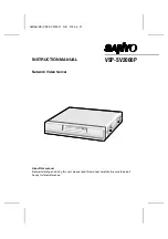
background image

INSTRUCTION MANUAL

Network Video Server

VSP-SV2000P

About this manual

Before installing and using this unit, please read this manual carefully. Be sure to keep it
handy for later reference.

L8NAA/XE 

(VSP-SV2000P) GB 2003, 

4, 

21

Summary of Contents for VSP-SV2000P

Page 1: ...ON MANUAL Network Video Server VSP SV2000P About this manual Before installing and using this unit please read this manual carefully Be sure to keep it handy for later reference L8NAA XE VSP SV2000P GB 2003 4 21 ...

Page 2: ...Post alarm Recording 34 Recording New Alarm Data 35 Fixed Settings During Pre Post Alarm Recording 35 Saving to an Expansion Memory Card 36 Viewing Live Images 37 Viewing the View Frame Screen 38 Playing Back Alarm Data 39 Playing Back Alarm Data in the Video server s Internal Memory 39 Descriptions of Alarm Operation Buttons 39 Playing Back Expansion Memory Card Images 40 Playing Back Alarm Image...

Page 3: ...sformer audio speakers the magnetic field they generate will distort the image Protect from humidity and dust To prevent damages to the video server do not install it where there is greasy smoke or steam where the dampness may get too high or where there is a lot of dust Protect from high temperatures Do not install close to stoves or other heat generating devices such as spotlights etc or where i...

Page 4: ... The images captured by the video server are compressed using the JPEG2000 format before transmission In comparison to conventional JPEG formats this format produces very little image deterioration and allows large volumes of data to be transmitted quickly maximum 30 fps Note The transmission rate will vary depending on individual network conditions A network environment that can transmit data at ...

Page 5: ...t Corporation in the United States and or other countries CPU Intel Pentium III 800 MHz or higher or similar with equivalent speed capacity Pentium 4 2 GHz recommended Intel and Pentium are trademarks or registered trademarks of Intel Corporation or its subsidiaries in the United States and other countries Memory 128 MB or more 256 MB or more recommended Drive CD ROM drive Network card 10Base T 10...

Page 6: ...change the video server operation between modem and computer operation 5 RS 485 connector RS 485 Use this connector when connecting the video server to a device that is equipped with an SSP RS 485 communication function After making the connection select the connected device in the SSP sub menu of the main menu so that the device can be operated by remote control via the network 6 Communication te...

Page 7: ... output terminals of the monitoring cameras Video output terminals VIDEO OUT 1 4 Connect these terminals to a monitor for pass through output of the images to the monitor G POWER indicator This indicator illuminates when 12 V DC is supplied to the power terminals H PC card slot Insert a memory card or wireless LAN card into this slot At the time of shipment from the factory a dummy card is inserte...

Page 8: ...with the video server and the power supply take sufficient care to ensure that the polarities are correct when connecting the power supply When the accessory ferrite cores are attached they will increase the load on the cable so after doing the installation adjust the cable accordingly 3 Insert the power cord plug into a wall outlet The POWER indicator will illuminate Computer Monitor TV CCD camer...

Page 9: ...t type Ethernet cable If connecting to an ADSL modem or to some other type of device refer to the documentation provided with the device for details on what type of connection method should be used Ethernet cable straight type Ethernet switching hub LAN IN OUT VIDEO 2 IN A RS 232C COM ALARM OUT RS485 TERMI ON MODEM ETHERNET ALL RESET PC B A B OUT VIDEO 3 IN OUT VIDEO 4 1 2 Internet Ethernet cable ...

Page 10: ...n 2 Wired LAN Settings p 13 Connect an Ethernet cable between the network video server and the computer and then make the required initial settings such as the computer IP address user name password and language When these settings are completed the initial network video server screen will be displayed This section gives descriptions of the various parts of the initial screen for you to refer to 3...

Page 11: ...OM drive of the computer 3 Click Start and then click Run 4 Type D Setup exe Type the drive letter for the CD ROM drive of the computer in place of D 5 Click the OK button After a short wait the installation window will appear Note Simply answer the prompts that appear on the screen in order to continue installing the software The installation program has been set up beforehand to install the soft...

Page 12: ...e software will start and the window display will change to show the installation progress 10 Click the Finish button This completes the installation of the plug in software Uninstalling the plug in software To uninstall the plug in software select Add Remove Programs from the Windows Control Panel and delete J2KCORE L8NAA XE VSP SV2000P GB 2003 5 12 English 11 ...

Page 13: ...ols and plug ins in the ActiveX controls and plug ins section 2 Click Enable for Active scripting in the Scripting section and then click the OK button Cookie Settings The video server uses cookies If using Internet Explorer Version 6 0 as the web browser select Internet Options from the Tools menu click the Privacy tab move the slide bar to the Medium or lower position and then click the OK butto...

Page 14: ...video server s IP address is set to 192 168 0 2 so type in a spare number that is 3 or higher for the IP address Example 192 168 0 101 Subnet mask setting Type in 255 255 255 0 3 Start the web browser on the computer type http 192 168 0 2 into the location bar and then press the Enter key The password entry window will be displayed 4 Type in the username ID3 and the password 3333 and then click th...

Page 15: ... images that are being transmitted Available settings AUTO default setting The live images being transmitted are automatically adjusted in accordance with the computer FINE The live images being transmitted are displayed at high quality The actual image display quality will vary depending on the original quality at the time of transmission Note The quality of the images will vary depending on the ...

Page 16: ...n making network settings WIRELESS LAN button Used when making wireless LAN settings PPP button Used when setting up an Internet connection using a modem Archive software sold separately is required when using these settings DISPLAY button Used when making settings such as camera title and image quality aperture and contrast for a camera ALARM button Used when making settings for alarm recording a...

Page 17: ...ntinuous output or timed output Black indicator No output status when ALARM OUT TIME has been set Red indicator Output status when ALARM OUT TIME has been selected When the set time is exceeded the indicator changes to black but if you click the indicator once more the specified indicator illuminates Grey indicator No output status when ALARM OUT TIME is set to REMOTE Orange indicator Output statu...

Page 18: ...mputer being used In addition if other applications besides the web browser are running this may also cause the image refresh rate to become slower or may result in unstable operation You should avoid running other applications at the same time as much as possible Set the FRAME RATE PICTURE QUALITY COMPRESSION RATIO and RESOLUTION settings to levels that will not interfere with the operation of th...

Page 19: ...s available User Operator and Administrator and separate passwords can be set for each level The factory default settings are shown in Table 1 p 21 and the range of operations varies as indicated for each access level Note It is recommended that you change the passwords whenever possible for security purposes p 19 5 NETWORK SPEED This sets the speed of data transmission by the video server Availab...

Page 20: ...el user will have priority In such cases the Operator level user will be disconnected and the message THE UNIT IS DISCONNECTED will be displayed on their screen If an Operator or Administrator attempts to access the video server while another user with the same access level is accessing the video server the second access will have priority In such cases the first access will be disconnected and th...

Page 21: ...l be displayed Note If the ID1 password is blank a single image live image screen will always be displayed To return to normal password entry type in a password for ID1 example 1111 Changing the Access Level ID2 or ID3 If live images are monitored without using a password the SET button will change to CHANGE ID To change the access level to ID2 or ID3 follow the procedure below 1 Click the CHANGE ...

Page 22: ...level All operations and settings can be carried out Username ID3 Password 3333 For Operator access level The following buttons and the transmission setting menu can be used The ALARM DATA LIST screen cannot be displayed Username ID2 Password 2222 For User access level Only the following buttons can be operated Username ID1 Password 1111 The transmission setting menu in the live image screen is di...

Page 23: ...n list box and then click the SET button UNSET If the time has not been set when you log in default setting it will be set automatically LOGIN The time is set automatically each time you log in OFF The time is not set Note Make sure that the computer s time is set correctly 4 DAYLIGHT SAVING MODE The daylight saving settings are displayed when USE is selected from the drop down list box Available ...

Page 24: ...era title 2 Type in the new camera title example CAM_1 2 3 4 The camera title can consist of up to eight alphanumeric characters and the underscore character Note The only characters that can be used in camera titles are alphanumeric characters If any other characters are entered they will appear as _ underscore 3 Click the SET button The camera title that has been typed in will be saved and it wi...

Page 25: ... be transmitted by the video server for that screen so the amount of transmission data handled by the network will be reduced Setting Image Quality Aperture and Contrast This lets you set the aperture contour correction and contrast 1 APERTURE Select HIGH if you want to emphasize the contours of objects Available settings NORMAL HIGH 2 CONTRAST Available settings LOW When viewing mainly dark scene...

Page 26: ...hat is displayed when the SINGLE VIEW button is clicked will vary depending on the SSP CONTROL setting ON OFF p 52 SSP CONTROL OFF SSP CONTROL ON 1 MULTI VIEW Returns to the multi screen display 2 POP UP The control panel of the SSP control panel can be displayed in a separate window 1 2 OFF Only switching between single screen and 4 screen display is possible ON The control panel for carrying out...

Page 27: ...ARM indicator and the ALARM DATA indicator illuminate simultaneously When images are being recorded in the video server s internal memory the ALARM indicator switches off and the ALARM DATA indicator illuminates red or green Playback of alarm recording images is possible at this time Alarm checking Output When an alarm has been detected by either an external alarm sensor or a motion detector the a...

Page 28: ...ndicator black is displayed in the initial screen p 32 5 ALARM OUT TIME This sets the alarm duration when the external alarm or motion detector detects an alarm The REMOTE setting only appears when ALARM OUT MODE is set to REMOTE CONTROL p 27 Available settings 2 5 10 15 20 30 60 sec 2 3 4 5 min REMOTE 6 ALARM SOUND MODE This setting causes an alarm warning to sound when an alarm is detected If se...

Page 29: ... 16 12 MB All available alarm recording area ratios can be selected 8 MB The 1 9 pre post ratio cannot be selected 4 MB The 1 9 and 2 8 pre post ratios cannot be selected 2 MB The pre post ratio is fixed at 0 10 TWO IMAGES The pre post ratio is fixed at 0 10 Note TWO IMAGES can be selected when PPP is being used Only a single event can be stored in the internal memory regardless of the size of the...

Page 30: ...NO example For example if a door is opened it will trigger an alarm For details see 8 EXTERNAL ALARM 9 Set ALARM BUFFERING to ON and then click the SET button The display will return to the ALARM CONDITIONS SET screen 10Set ALARM BUFFERING to ON and then click the DETAIL button The ALARM BUFFERING SET screen will be displayed 11Change any settings that are required for recording alarm images into ...

Page 31: ... MOTION DETECTOR LEVEL setting example 2 The smaller the value selected the higher will be the sensitivity Refer to Motion Detector Level Sensitivity Setting for further details p 32 6 Set the sensor marks These correspond to the live image screen and the sensing area 1 Move the pointer to the same position grid area as the area of the live image screen that you would like sensing to be carried ou...

Page 32: ...st box to change the MOTION DETECTOR LEVEL setting example 2 The smaller the value selected the higher will be the sensitivity Refer to Motion Detector Level Sensitivity Setting for further details p 32 6 Set the sensor marks Refer to MOTION DETECTOR SET Settings 7 Set ALARM MODE to OR example An alarm will then be triggered if either the motion detector or the external alarm sensor detects someth...

Page 33: ...s in the optimum positions and set the sensitivity and then click the SET button Remote Alarm Operations You can use the REMOTE ALARM indicator to set alarm output to come out from the ALARM OUT terminal at the rear of the video server for a specified period or continuously regardless of the actual alarm detection status A Alarm Output for a Specified Period 1 Set ALARM OUT to NO example 2 Set ALA...

Page 34: ...ve image screen The REMOTE ALARM indicator gray will be displayed in the initial screen 4 While monitoring the live images click the REMOTE ALARM indicator The REMOTE ALARM indicator will illuminate orange and an alarm will be output continuously If you repeatedly click the indicator the continuous alarm output will turn on and off each time you click the indicator 1 2 3 L8NAA XE VSP SV2000P GB 20...

Page 35: ...creen If high quality and a large image size have been set it will take longer for the images to be refreshed B Pre alarm Post alarm Recording When an alarm is detected recording is assigned between the pre and post alarm recording areas in the ratio specified You can increase or decrease the length of time that images are recorded before an alarm is detected 1 Set BUFFERING AREA to PRE POST 2 8 2...

Page 36: ...l memory can be saved into a computer as still images Fixed Settings During Pre Post Alarm Recording If the pre alarm post alarm recording area ratio is set to something from 1 9 to 5 5 so that pre alarm recording can be carried out the transmission settings PICTURE QUALITY RESOLUTION and IMAGE MODE COLOR are fixed Example 1 If PRIORITY is set to PICTURE QUALITY The image quality during pre and po...

Page 37: ... card eject button the card is unlocked and the memory card can then be pulled out 2 Insert the expansion memory card The alarm data in the internal memory will be automatically moved to the memory card The data will be deleted from the recording areas of the internal memory at this time 3 The ALARM DATA indicator green will illuminate If alarms are repeatedly detected in this condition the alarm ...

Page 38: ...rease or decrease depending on the settings that are made here You can switch between multi screen 4 screen and single screen 1 screen displays using the menu select buttons 3 If you click the MULTI VIEW button the screen will become a 4 screen split screen If you click the SINGLE VIEW button the images will be displayed in a single screen and SSP transmission operations will be possible Note If y...

Page 39: ... screen size of 720x480 regardless of the screen size that has been set in the live image screen To return to the live image screen click the BACK button Note Even if the image size has been set to a smaller size 160x120 or 320x240 the images will still be displayed at a size of 720x480 In this case the image resolution will appear coarser L8NAA XE VSP SV2000P GB 2003 5 12 38 English ...

Page 40: ...tandby You can then click the PLAY button to play back the data 2 PLAY button Click this button during playback standby or when playback is paused to start playback 3 STOP button If you click this button while playback is in progress playback will stop 4 FRAME RATE You can select the playback speed for alarm images using the drop down list box If you change the speed while alarm images are in the ...

Page 41: ...g is complete the BUFFER DATA VIEW screen will be displayed the PRE or POST indicator will illuminate and playback of the alarm images will start automatically When playback is finished the END indicator will be displayed Playing Back Alarm Images Stored in a Computer Refer to p 44 for details on saving alarm data into a computer 1 Using Windows Explorer click on the download destination and then ...

Page 42: ... image number The image number changes depending on the playback status 4 TOP Displays the first image in the data and also displays the first image number 5 PREVIOUS Reverses playback one frame at a time 6 REVERSE Reverses playback 7 STOP If clicked while playback is in progress playback stops 8 PLAY Starts playback 9 NEXT Carries out playback one frame at a time F END Displays the last image in ...

Page 43: ...d and then click the DELETE button The alarm data delete confirmation dialog box will be displayed 3 Click the OK button The alarm data will be deleted Note When deleting more than one set of alarm data at the same time the message THE UNIT IS REMOVING ALARM DATA will be displayed briefly and then the selected alarm data will be deleted and the screen will return to the live image screen L8NAA XE ...

Page 44: ...images will be saved at the selected resolution The extension used for the saved images will be jp2 Saving Alarm Images onto a Computer as Still Images Alarm images can be saved as still images in the computer s storage area in JPEG2000 format 1 Right click the mouse on the alarm image to be saved The images will be paused and an image save pop up menu will be displayed 2 Click Save JPEG2000 File ...

Page 45: ...ata is being downloaded 4 When the File Download pop up menu is displayed click Save The Save As dialog box will be displayed 5 Specify the saving destination and the filename and then click the Save button The download will then start Do not click in the network video server screen 6 Using Windows Explorer click on the download destination and then double click the alm_viewer_XXXX html file The d...

Page 46: ...ireless LAN card into the video server so that it is facing in the right direction and the card will lock in place 2 Press the PC card removal button A to release the lock and then remove the wireless LAN card Note It is recommended that you use one of the following commercially available wireless LAN devices that have been tested by SANYO In addition consult your local dealer for advice on purcha...

Page 47: ... The ESS ID can consist of up to 23 alphanumeric characters 4 Set the encipherment method Because the video server and the wireless LAN device communicate by means of radio waves there is the possibility that wireless packets could be intercepted and decoded by outsiders It is recommended that you complete the encipherment setting in order to provide greater security p 47 5 Make the TCP IP setting...

Page 48: ...key can be set Rules for encryption key entry WEP40 The encryption key can consist of up to 5 alphanumeric characters WEP128 The encryption key can consist of up to 13 alphanumeric characters Encipherment Settings If you do not type in the same encryption key that has been set for the wireless LAN device communication will not be possible Make a note of the encryption key and type it in Example En...

Page 49: ...ng alarm data Refer to Video Server PPP Settings p 50 for details Note After making the PPP settings close the video server setting screen 5 Install the Network Archiving Software onto the computer Note After installing the software close the software window 6 Make the Camset settings Camset only makes the settings that are required for setting up the video server Refer to the documentation for th...

Page 50: ... NO USE CAMERA ID Type in a unique 4 character camera name 5 Click the SET TO CAMERA button The settings will be loaded into the video server 6 Click the SAVE INFO FILE button The settings will be applied to the Network Archiving Software 7 Close the Camset window Note The video server cannot be accessed using the computer s web browser while the video server is connected to the modem Use a wired ...

Page 51: ...s sets the type of telephone circuit that the modem is connecting to Available settings TONE For tone dialing circuits PULSE For pulse dialing circuits Note Set to TONE if using a terminal adapter 6 Type in any AT commands that are required to control the modem Type in AT at the beginning and then type in the commands specified by the modem manufacturer followed by a command to change flow control...

Page 52: ...ect button The RS 232C SET screen will be displayed Select the communication speed from the drop down list box and then click the SET button The setting will then be saved The default setting for the communication speed is 19200 bps Available settings 9600 19200 38400 57600 115200 Note If you click the MULTI VIEW button the display will return to the live image screen L8NAA XE VSP SV2000P GB 2003 ...

Page 53: ...ion from the drop down list box If you select POP UP the control panel will be displayed in a separate window when single screen images are being displayed Available settings FIXED POP UP 6 Select the CATEGORY setting for each channel The available categories are as shown below CAM Camera MPX Multiplexer VCR Time Lapse Video Cassette Recorder DVR Digital video recorder 7 Select the ADDRESS setting...

Page 54: ...Figure 1 Figure 1 4 ADDRESS Use this to select the addresses of the connected devices 5 KEY Select this when operating a camera that is connected to a multiplexer for example when CATEGORY is set to MPX At this time the control panel changes to the camera control panel and the camera can then be operated 6 MULTI VIEW button Click this button to close the SSP operating screen The display will retur...

Page 55: ...t the dome camera Note Camera A is for monitoring images only it cannot be operated using the CAM buttons Note The twisted pair cables should always have signal A connected to signal A and signal B connected to signal B and the ground should always be connected too If more than one device is connected enable the termination settings for the devices at both ends of the series Set communication term...

Page 56: ...TUS menu select button The STATUS screen will be displayed Note If you click the MULTI VIEW button the display will return to the live image screen 1 FIRMWARE VERSION This shows the version number for the video server s firmware 2 SUB MICROCOMPUTER VERSION This shows the version number for the video server s sub microcomputer 3 PCMCIA SOCKET STATUS This shows the usage status for the PC card slot ...

Page 57: ...uter being used FTP File Transfer Protocol A protocol communication standard for transmitting files via the Internet This communication protocol allows files and data to be transferred via the Web whereas previously it was only possible using e mail Hard disk A storage device for large quantities of data that is used by equipment such as computers It contains a flat disc that is coated with magnet...

Page 58: ...etwork devices and determines what route should be used for the information to be transmitted to and from these devices SMTP Simple Mail Transfer Protocol A protocol communication standard for sending and receiving electronic mail via the Internet and Intranets It controls the flow of mail between servers and is also used when clients send mail Stop bit A symbol that is added at the end of a byte ...

Page 59: ...g to the ratio selected When an alarm is detected images from before the alarm that fall within the amount specified by the ratio selected are recorded in the pre alarm area of the internal memory For example if the alarm recording area of the internal memory is set to a ratio of 3 7 30 of the available area is devoted to recording images from immediately before the alarm is detected Actual alarm ...

Page 60: ...rget the IP Address If you forget the video server s IP address you can check it using the following procedure 1 Set pin 2 of the communication terminal select switch at the rear of the video server to the MODEM setting turn off the video server s power wait three seconds or more and then turn the power back on 2 Set pin 2 of the communication terminal select switch at the rear of the video server...

Page 61: ...S 1 0 Vp p 75 Ω BNC connector 4 pairs Other functions Color Black white selectable built in clock function Interfaces Ethernet connector 10 100 Base T RJ 45 RS 232C connector D Sub 9 pin PC card slot PCMCIA Type II 5 V power supply only Pre post alarm buffer 16 MB Protocols TCP IP PPP FTP HTTP Software Plug in browser Internet Explorer Ver 5 5 SP2 or later or equivalent Clock backup 8 hours Operat...

Page 62: ......

Page 63: ......

Page 64: ...Printed on recycled paper 1AC6P1P2600 A L8NAA XE 0503KP CZ SANYO Electric Co Ltd Printed in Japan L8NAA XE VSP SV2000P GB 2003 4 21 ...

Reviews: