background image

INSTRUCTION MANUAL
BEDIENUNGSANLEITUNG
MANUEL D’INSTRUCTIONS
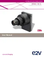
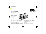
VCC-6574P

COLOUR CCD camera

CCD-Farbkamera

Caméra CCD COULEUR

CCD

About this manual

Before installing  and using the camera, please read this
manual carefully. Be sure to keep it handy for later reference.

Über diese Bedienungsanleitung

Lesen Sie bitte vor der Montage und dem Inbetriebnehmen der
Kamera zuerst diese Bedienungsanleitung sorgfältig durch und
bewahren Sie sie zum späteren Nachschlagen auf.

A propos de ce manuel

Avant d’installer et d’utiliser la caméra, veuillez lire ce
manuel attentivement. Gardez-le à portée de main
pour toute référence ultérieure.

L53X4/XE GB 2001, 

2, 

23

I

i n d ex

Summary of Contents for VCC-6574P

Page 1: ... to keep it handy for later reference Über diese Bedienungsanleitung Lesen Sie bitte vor der Montage und dem Inbetriebnehmen der Kamera zuerst diese Bedienungsanleitung sorgfältig durch und bewahren Sie sie zum späteren Nachschlagen auf A propos de ce manuel Avant d installer et d utiliser la caméra veuillez lire ce manuel attentivement Gardez le à portée de main pour toute référence ultérieure L5...

Page 2: ...TURES Built in interline transfer method 1 3 CCD approx 470 000 picture elements Equipped with a DSP Digital Signal Processor function Horizontal resolution more than 520 TV lines High sensitivity minimum required illumination is 1 0 lux F1 2 Two types of backlight compensation functions multi spot photometry and center focus photometry Low smear anti blooming low lag no burning and no geometric d...

Page 3: ...dio speakers the magnetic field they generate will distort the image Protect from humidity and dust To prevent damages to the camera do not install it where there is greasy smoke or steam where the dampness may get too high or where there is a lot of dust Protect from high temperatures Do not install close to stoves or other heat generating devices such as spotlights etc or where it could be subje...

Page 4: ... minimized by turning this volume 3 Power indicator POWER Comes on when the power to the camera is on 4 24 V AC input terminal AC 24 V GND Power supply connections Use a 3 wire grounded cable 22 AWG or more and connect as shown by the illustration CAUTION To prevent camera and or AC adaptor failure pay close attention to polarity when making the connections To prevent fire hazard any UL listed wir...

Page 5: ...n bracket The bracket can be fixed at the top or bottom of the camera When fixing the bracket be sure to use the longer screws and install the shorter screws on the opposite side to seal the openings CAUTION When installing the camera support select a location that can support the total weight of the camera and accessories 1 Shorter screws M3 x 4 2 Longer screws M3 x 6 3 Camera mounting screw hole...

Page 6: ...r type lens However if due to installation conditions or environment the settings may need to be modified for best results see SETTINGS To access the controls remove the cover fixing screw then remove the cover Notes When using a 1 2 or 2 3 inch C mount VIDEO with EE internal amplifier auto iris type lens set the A I LENS switch to the VIDEO position If not using an auto iris lens make sure the sw...

Page 7: ...le on the lens for iris adjustments Set the A I LENS switch to the VIDEO position Compatible auto iris lenses 1 3 inch Sanyo DC type lens VIDEO type lens VCL CS8LY Standard angle f 8 mm Standard angle f 9 mm VCL CS4LY Wide angle f 4 mm Telephoto angle f 12 mm VCL CS2LY Ultra wide angle f 2 8 mm Greater telephoto angle f 16 mm If using a VIDEO type auto iris lens Set the ALC and LEVEL controls on t...

Page 8: ...ount then carefully align the lens mount with the camera opening and turn the lens slowly to install it 3 Connect the lens plug to the lens iris output connector LENS on the side of the camera When using lenses from other makers the plug shape may not correspond to the terminal on the camera In such a case remove the original plug and using a soldering iron connect the supplied lens iris plug acco...

Page 9: ... If the pick up surface is not correctly positioned with relation to the lens focal point the picture will be out of focus in particular when using auto iris power zoom lenses sold separately If that is the case adjust the flange back position as described below 1 Using a screwdriver loosen the FLANGE BACK LOCK screw M2 2 Set the zoom lens to the maximum telephoto position set the focus using the ...

Page 10: ...er to prevent electromagnetic interference to the other devices connected 3 Insert the plug of this power cord into a wall outlet The POWER indicator A will light Adjust the picture on the monitor using the Brightness and Contrast controls etc Coaxial cable type and maximum length Cable type RG 59U 3C 2V 250 m maximum Cable type RG 6U 5C 2V 500 m maximum Cable type RG 11U 7C 2V 600 m maximum CAUTI...

Page 11: ...peed electronic shutter ES setting 1 50 sec 2 Electronic Iris EI Auto iris AI switch AI 3 Aperture compensation switch sharp SHRP normal NORM SHRP 4 Backlight compensation mode setting Center CENT Multi MULT MULT 5 Backlight compensation switch BLC OFF 6 White balance switch WB and colour R or B adjustment volume ATW 7 Syncronisation SYNC setting INT LL INT 8 Auto iris lens switch A I LENS see pag...

Page 12: ...A switch 1 3 1 1 50 2 1 120 3 1 250 4 1 500 5 1 1000 6 1 2000 7 1 4000 8 1 10000 Unit sec Iris function setting This should normally be set to the down AI position Use a manual or fixed iris lens and set the lens aperture to the shortest F stop Set the switch 4 IRIS to the up EI position Note Please refer to the specifications for dynamic range of the electronic iris CAUTION The electronic iris is...

Page 13: ...f conditions are outside the electronic iris operation range or more than the maximum illumination it will cause saturation of the CCD In that case use a manual iris lens Aperture If you would like to emphasize the contours of the object set the switch 5 APER to the up SHRP position 5 L53X4 XE GB 2001 2 23 12 English ...

Page 14: ...osition when applying backlight compensation to only the central portion of the screen Note When using the backlight compensation function set the switch 7 to the up ON position When not using the function set the switch 7 to the down OFF position When MULT mode is set scenes with no backlighting may appear extremely dark and the object may appear over exposed If this happens move the switch 6 to ...

Page 15: ...ay be a vertical roll of the images when switched In such a case set as described below 1 Set the switch 9 SYNC to the up LL position 2 Switch the display on the monitor from camera 1 to camera 2 Adjust the LINE PHASE volume on camera 2 until the vertical roll of the image stops If more than two cameras are used please repeat this procedure for all the cameras CAUTION If the vertical roll cannot b...

Page 16: ...onditions described below L counterclockwise To decrease the contrast H clockwise To increase the contrast If shooting simultaneously in a dark room and through a bright window If the subject background is extremely bright or dark If the brightness of the picture on the monitor is not correct VR301 L53X4 XE GB 2001 2 23 English 15 ...

Page 17: ...itch must be set accordingly Is the iris control correctly set The picture is not clear Is the monitor correctly adjusted Is the flange back position correctly set Is the lens focus correctly adjusted Are the lens surfaces clean If there is dust or finger prints on the lens the image quality will deteriorate To clean the lens use a soft cloth or a commercially available lens cleaning set SERVICE T...

Page 18: ...witching Electronic iris range 1 0 lux to 50 000 lux F 1 2 lens Electronic shutter 8 speeds selectable by switches 1 50 1 120 1 250 1 500 1 1000 1 2000 1 4000 1 10000 sec Flange back 12 5 mm 0 5 mm White balance ATW Manual switching Lens mount CS mount or C mount with the supplied adaptor Environmental conditions Temperature 10 C 50 C Humidity less than 90 no condensation Power supply 24 V AC 50 H...

Page 19: ...SPECIFICATIONS Dimensions Features and specifications are subject to change without prior notice or obligations 12 6 22 4 11 0 5 109 100 56 45 28 1 4 20 UNC L53X4 XE GB 2001 2 23 18 English ...

Page 20: ...1AC6P1P2399 L53X4 XE 0101KPS DSP a Sanyo Electric Co Ltd Printed in Japan L53X4 XE GB 2001 2 23 ...

Reviews: