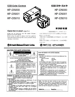
INSTRUCTION MANUAL
BEDIENUNGSANLEITUNG
MANUEL D’INSTRUCTIONS
VCC-4594P
VCC-4592P
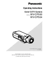
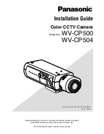
COLOUR CCD camera
CCD-Farbkamera
Caméra CCD COULEUR
CCD
About this manual
•
Before installing and using the camera, please read this manual
carefully. Be sure to keep it handy for later reference.
•
This manual gives basic connections and operating instructions for 2
PAL models (VCC-4594P, 4592P).
Über diese Bedienungsanleitung
•
Lesen Sie bitte vor der Montage und dem Inbetriebnehmen der
Kamera zuerst diese Bedienungsanleitung sorgfältig durch und
bewahren Sie sie zum späteren Nachschlagen auf.
•
In dieser Anleitung finden Sie die Anschlüsse und die
Grundbedienung für 2 PAL-Modelle (VCC-4594P und 4592P)
A propos de ce manuel
•
Avant d’installer et d’utiliser la caméra, veuillez lire ce manuel
attentivement. Gardez-le à portée de main pour toute référence
ultérieure.
•
Ce manuel couvre les branchements et instructions pour
l’utilisation de base pour 2 modèles de format PAL
(VCC-4594P et 4592P).
2
PAL
VCC-4594P, 4592P
L53Z4/XE GB 2001,
5,
23
I
i n d ex