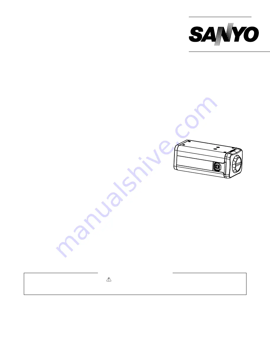
background image

SERVICE MANUAL

B/W CCD Camera

VCB-3385P

(Product Code : 117 076 01)
(Europe, Russia)
(Asia, Mideast, China)
(Australia, New Zealand)

FILE NO.

REFERENCE No. SM5310534

L73R2/XE

NOTE : 1. Parts order must contain model number, part number, and description.
             2. Substitute parts may be supplied as the service parts.
             3. N. S. P. : Not available as service parts.

Design and specification are subject to change without notice.

The components designated by a symbol ( 

 ) in this schematic diagram designates components whose value are of

special significance to product safety. Should any component designated by a symbol need to be replaced, use only the

part designated in the Parts List. Do not deviate from the resistance, wattage, and voltage ratings shown.

PRODUCT SAFETY NOTICE

CONTENTS

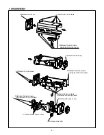
1. DISASSEMBLY ....................................2
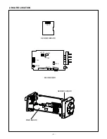
2. BOARD LOCATION ............................. 3
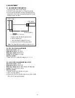
3. ADJUSTMENT .....................................4
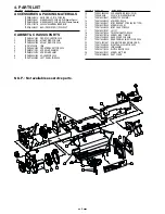
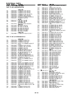
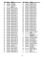
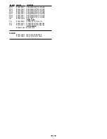
4. PARTS LIST .........................................5
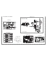
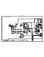
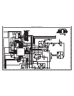
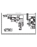
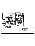
CIRCUIT DIAGRAMS & PRINTED
WIRING BOARDS ..................................C1

SPECIFICATIONS

Scanning system : 

CCIR standard (625 scanning lines, 25 frames/sec.)

Interlace :

 PPL 2:1 interlace

Image device : 

1/3 inch solid state CCD

Number of pixels : 

795 (Horizontal) x 596 (Vertical)

Number of pixels in image area : 

752 (Horizontal) x 582 (Vertical)

Synchronizing system : 

 Internal sync/ Line lock (manually switched)

                                          External sync (automatic switched)

Resolution : 

570 TV lines

Video output terminal : 

1.0 Vp-p/75 

, composite

Image S/N ratio : 

50 dB min.

Electronic shutter speed : 

1/50 - 1/100,000 sec.

Minimum required illumination : 

0.07 lux approx. (with F 1.2 lens, 50 IRE)

Backlight compensation ON/OFF : 

Set to “ON” or “OFF”

Auto Iris lens output : 

DC output (variable DC level), 4-pin terminal

Lens mount : 

CS mount

Flange-back : 

12.5 mm (adjustment range : 

±

 0.5 mm)

Auto Iris lens switching : 

EI/VIDEO/DC

Attachment screw hold diameter

 : 1/4

- 20UNC (top or bottom surface)

Operating environment : 

Ambient temperature: -10 to + 50 

°

C (14 to 122 

°

F)


Humidity:  90 % RH max.

Power supply : 

24 V AC/50Hz, 12 - 15 V DC

Power consumption : 

3.0W approx.

Weight : 

245 g approx.

Summary of Contents for VCB-3385P

Page 1: ...PRINTED WIRING BOARDS C1 SPECIFICATIONS Scanning system CCIR standard 625 scanning lines 25 frames sec Interlace PPL 2 1 interlace Image device 1 3 inch solid state CCD Number of pixels 795 Horizontal x 596 Vertical Number of pixels in image area 752 Horizontal x 582 Vertical Synchronizing system Internal sync Line lock manually switched External sync automatic switched Resolution 570 TV lines Vid...

Page 2: ...ull out the rear cover 4 Remove the lens cap 5 Remove the two screws and pull out the front cover 7 Remove the four screws and remove the main board 8 Remove the one screw 6 Remove the two screws 9 Remove the two screws and remove the CCD holder 10 Remove the IRIS 11 Remove the seven screws ...

Page 3: ... 3 2 BOARD LOCATION SENSOR BOARD P001 MAIN BOARD SENSOR BOARD T102 MAIN BOARD P103 VR104 P105 VR102 S102 VR103 P104 VL101 ...

Page 4: ...with VL101 so that the voltage is 2 1 0 1 V 3 3 AGC LEVEL ADJUSTMENT BLC OFF Adjustment location VR102 Measuring location VIDEO OUT Measuring equipment Waveform Monitor Oscilloscope Subject Gray scale chart γ 0 45 Adjusting method 1 Display the gray scale chart on full screen 2 Open iris of lens to MAX 3 Adjust with VR102 so that the video level is 105 5 IRE 750 50 mV during video output L Distanc...

Page 5: ...2 X 5MM NI 7 TCZM82 0120700 SCREW M2 X 3 MM 8 TCZM05 0531000 HOLDER FOR C006 9 TCZM11 0006000 LEFT PANEL FOR C006 10 TCZE42 0504090 CCD SENSOR ICX409AL CCIR 11 TCZE4B 9400 C006 1 3 B W SENSOR MAIN 12 TCZM82 0120601 SCREW TP2 X 5 MM NI 13 TCZM20 0631000 SPRING FOR C006 14 TCZM15 0310001 BODY BRACKET FOR C006 DC TYPE 15 TCZM82 0110409 SCREW M3 3 5 NI 16 TCZM14 0310000 BODY CASE FOR C006 17 TCZM82 01...

Page 6: ...210601 TANTALUM CAPCONDERSOR 10UF 10V SMD A SIZE C160 TCZE63 4110772 100U 16V 6 3 8 MVL 105Åé CMC C161 TCZE63 4810452 CONDERSOR 0 1UF 16V 0402 Y5V C162 TCZE63 4810452 CONDERSOR 0 1UF 16V 0402 Y5V C163 TCZE63 4810452 CONDERSOR 0 1UF 16V 0402 Y5V C164 TCZE63 4810452 CONDERSOR 0 1UF 16V 0402 Y5V C165 TCZE63 4847025 CONDERSOR 47P 50V C0G C166 TCZE63 4510611 CERAMIC CONDENSER 10UF 10V 1206 C167 TCZE63 ...

Page 7: ... TCZE61 4818332 RESISTANCE 18K OHM 5 0402 R171 TCZE61 4868132 RESISTANCE 680 OHM 5 0402 R172 TCZE61 4851132 RESISTANCE 510 OHM5 0402 R173 TCZE61 4818332 RESISTANCE 18K OHM 5 0402 R174 TCZE61 4868132 RESISTANCE 680 OHM 5 0402 R175 TCZE61 4847132 RESISTANCE 470 OHM 5 0402 R176 TCZE61 4800032 RESISTANCE 0 OHM 5 0402 R177 TCZE61 4810232 RESISTANCE 1K OHM 5 0402 R178 TCZE61 4810332 RESISTANCE 10K OHM 5...

Page 8: ... 4W SMD ZD108 TCZE02 0205141 DIODE ZENER RLZ5 1B 0 4W SMD ZD109 TCZE02 0211041 DIODE ZENER RLZ11B 0 4W SMD LED TCZE02 0701020 DIODE LED CONNECTORS P103 TCZE76 0818050 CONNECTOR FH12 18S 0 5 SV P104 TCZE76 0904121 CONNECTOR MOLEX 53398 0428 P105 TCZE76 0904121 CONNECTOR MOLEX 53398 0428 MISCELLANEOUS TCZM50 0722000 BOSS MH4 8 4A CABLE TCZE79 1904040 CABLE HOUSING 40MM 4PIN TCZE79 5018030 CABLE FFC ...

Page 9: ...RING BOARDS TABLE OF CONTENTS BLOCK DIAGRAMS CIRCUIT DIAGRAMS Page OVERALL BLOCK C3 U101 U102 U103 BLOCK C3 CIRCUIT WAVEFORMS C3 SENSOR BOARD CIRCUIT C3 MAIN BOARD CIRCUIT C4 PRINTED WIRING BOARDS P W B SENSOR P W B C9 MAIN P W B C9 ...

Page 10: ...EMATIC DIAGRAM DESIGNATES COMPONENTS WHOSE VALUE ARE OF SPECIAL SIGNIFICANCE TO PRODUCT SAFETY SHOULD ANY COMPONENT DESIGNATED BY A SYMBOL NEED TO BE REPLACED USE ONLY THE PART DESIGNATED IN THE PARTS LIST DO NOT DEVIATE FROM THE RESISTANCE WATTAGE AND VOLT AGE RATINGS SHOWN ...

Page 11: ...O P001 6 9 6 9 0 1 0 1 2 3 3 0 12 0 7 4 8 2 0 0 14 8 9 5 VOLTAGE POWER ON CONNECTOR CXA1310 NO SIGNAL DETECTION CIRCUIT VD DETECTION CIRCUIT SYNC DISCRIMINATION CIRCUIT GATE HV PLL SELECTOR LCIN COMP EVD EHD SYNC EXT HVDET VD HD EIA V DD 1 V DD 2 V SS 1 V SS 2 TEST LCOUT CKI CCD AVSS H1 H2 AVDD RG SHP SHD V1 V2 V3 V4 VL VM SUB VH SYNC CBLK CLP1 CLP2 BLC BLCW2 BLCW1 CV SS IRIN ED1 SPDNV ED2 Vreg CV...

Page 12: ...6 7 U114B NJM3414AM R1D4 100 15V C1B2 1u 10V R1D6 1M R1D5 47 R1D7 56 R VR104 VR 3362W 1 104 3 0 X0 12 X1 13 Y0 2 Y1 1 Z0 5 Z1 3 INH 6 A 11 B 10 C 9 X 14 Y 15 Z 4 VDD 16 VSS 8 VEE 7 U108 TC4053BF BFN C1A0 0 1u 5VA CLP1 3 2 1 8 4 U114A NJM3414AM C1A2 open C1A3 1u 10V C1A1 4 7u 16V 1 2 6 Q111A UMX1N 3 4 5 Q111B UMX1N HD2 WH C1A8 10u 25V 1 2 3 D120 1SS181 R113 1 8K C1A9 1u 16V 5VD 5VD MES 1 2 3 4 8 7 ...

Page 13: ... D117 MA111 R1C1 100K R1C2 8 2K R1D8 7 5K R1C5 10K R1C6 3 9K 5VA R1C3 1 8k C1A6 10u 10V C1A7 10u 10V R1C4 0 R1C0 10K 3 2 1 8 4 U116A NJM3414AM 5 6 7 U116B NJM3414AM R1C8 43K R1C7 10K R1C9 100K R1D0 20K R1D1 100 5VA C1B0 1u 10V D118 MA111 C1B1 10u 10V R1D2 20K R1D3 100K 5 6 7 U114B NJM3414AM R1D4 100 15V C1B2 1u 10V R1D6 1M R1D5 47 R1D7 56 R VR104 VR 3362W 1 104 3 0 X0 12 X1 13 Y0 2 Y1 1 Z0 5 Z1 3 ...

Page 14: ...R143 2 2K R144 2 2K SYNC R147 100K 5VD R141 0 R142 0 C145 120p C146 open C143 0 1u 0603 EVD PCO 5VD R150 30K C144 1000p R138 100k BLC R137 10 R136 10 SPUP SPDN R151 10k D108 MA111 ED0 D109 MA111 5VD V4 TO P103 TO P103 V3 V2 V1 SUB 15V VL R145 0 R146 0 HD RG H1 H2 CKI R139 100k R140 33k C140 0 1u R132 36k 1 R134 36k 1 R135 36k 1 C141 0 1u 25V R133 8 2k T119 5VD 5VD MES 1 2 3 4 8 7 6 5 1 9 10 11 12 ...

Page 15: ...15 1u 25V 118 111 5 D 6 7 FB 8 R121 3 9K C113 1000P C117 open C open ZD102 ZD RLZ3 6VB R 2k R123 2k 2 1 CN SYNC_IN ZD107 ZD 5 1V ZD108 ZD 5 1V SWITCHING CONTROL TO POWER ADAPTER 5VD SAG 1 GND2 2 GND1 3 SYNC 4 SCOONT 5 WCONT 6 DRIVE 7 GAMAO 8 LINER 9 GAMAC 10 GAMAI 11 AGCO 12 DETO 13 AGCM 14 VCC1 15 AGCC 16 OPOUT 17 OPIN 18 OPIN 19 SHD2 20 SHD1 21 DATA 22 PG 23 SHP 24 CLP2 25 GND3 26 IRIS 27 IRISC ...

Page 16: ...107 22uH CBLK L106 10UH R170 18K C164 0 1u R164 22k 1 5VA R167 75 R165 16 5k 1 R169 10 R166 22K 1 SHD SHP R168 100 C152 1u 10V C157 1u 10V R175 470 3 4 5 Q108B UMX1N 1 2 6 Q108A UMX1N R177 1k R176 0 C167 1u 10V VID_ VR102 100K 5 0 5VA 5VA C153 1u 10V CCD C160 100u 16V T104 VIDEO IRIS 5VA 5VA T106 AGC 5VA C154 47u 6 3V C155 CT10u 10V C159 CT10u 10V C166 10u 10V R157 10K R1F0 0 DRIVE VR101 10k R119 ...

Page 17: ...A B C D E F G H I J K 1 2 3 4 5 6 7 8 9 10 11 12 13 14 15 16 17 18 19 A B C D E F G H I J K C9 PRINTED WIRING BOARDS P W B SENSOR P W B SIDE A SENSOR P W B SIDE B MAIN P W B SIDE B MAIN P W B SIDE A ...

Page 18: ...Feb 04 SANYO Electric Co Ltd Osaka Japan SANYO Electric Co Ltd Osaka Japan ...

Reviews: