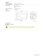
background image

 VCC-HD4600/HD4600P

Features of This Camera 

Specifications 

Target size and recording time 

Name and Function of Each Component 

Connections 

Settings with the Menu Screen 

Introduction1/23

Summary of Contents for THINK GAIA VCC-HD4600

Page 1: ...VCC HD4600 HD4600P Features of This Camera Specifications Target size and recording time Name and Function of Each Component Connections Settings with the Menu Screen Introduction1 23 ...

Page 2: ... stream video transmission it can simultaneously deliver up to four video image streams Because it allows video image compression format resolution and other image conditions to be set as desired for each stream you can choose the optimal video image for your application Equipped with a Variety of Functions With a 10 built in optical zoom lens the camera offers a zoom magnification of up to 160 in...

Page 3: ... Off Electronic shutter VCC HD4600P 1 25 1 50 1 120 1 250 1 500 1 1000 1 2000 1 4000 1 10000 VCC HD4600 1 30 1 60 1 100 1 250 1 500 1 1000 1 2000 1 4000 1 10000 Long exposure shutter 1 2 4 8 16 32 Iris AUTO MANUAL electronic iris ON OFF Digital PTZ Enables electronic pan tilt and zoom operations on clipped subject areas in VGA size Zoom magnification 2 max Camera settings Up to 2 patterns of monit...

Page 4: ...mal recording Alarm recording Backup recording in event of a network failure Log information recording External HDD Normal recording Alarm recording Backup recording in event of a network failure Log information recording Image video compression H 264 JPEG Video size H 264 16 9 1920 1080 1280 720 640 360 320 180 4 3 1600 1200 1280 960 1024 768 640 480 320 240 Video size JPEG 16 9 1920 1080 1280 72...

Page 5: ... condensation Power source 12 to 15 VDC 24 VAC 10 50 60 Hz PoE Power consumption 15 W PoE 12 3 W Weight 420 g 14 8 oz Dimensions Accessories 1 Power supply connector 2 CD ROM Appearance and specifications are subject to change without prior notice or obligations Introduction 5 23 ...

Page 6: ...n the PDF manual Refer to the table Target size and recording time in the electronic manual This table is displayed using a browser specific function and therefore not displayed on the PDF manual Refer to the table Target size and recording time in the electronic manual Introduction 6 23 ...

Page 7: ...itching terminals ALARM IN1 2 These input terminals can be used for either of the following purposes Alarm input Connecting an external switch infrared sensor or other device to these terminals enables the camera to detect alarm conditions such as the entry of an intruder Day Night switching Normally switching the camera between the color and black and white video modes is automatically accomplish...

Page 8: ... stereo plugs When recording live video onto an SD memory card insert the card into the slot For details refer to Formatting the recording media Use this socket to connect the camera to your PC to enable network operation For details refer to the Basic Connections section Link access indicator Green This indicator lights up approx 3 seconds after power on if a connection has been established betwe...

Page 9: ...ect a high definition monitor with HDMI interface For details refer to the Basic Connections section The indicator also works as an error indicator Power indicator The indicator lights up when the camera is powered on Error indicator The indicator blinks when an error occurs To activate the power or error indicator via network operation on the OPTION SETTINGS screen change the setting for POWER LE...

Page 10: ...et the focus to a near target press the button to set the focus to a far target Live screen control panel ZOOM Press the button to zoom out of the image press the button to zoom into the image Live screen control panel B Menu screen operations Press the SET button for 2 seconds or more to display the menu screen For details refer to the Settings with the Menu Screen Operation Associated button and...

Page 11: ... power indicator starts blinking and then stay lit when the camera is ready for you to remove the recording media SD HDD Resuming recording Recognizing the recording medium Press the and SET buttons simultaneously The power indicator starts blinking and then stay lit after the camera recognizes the recording medium and is ready for recording SD HDD Resetting the login password for default users on...

Page 12: ...nts of your system Improper connection may cause smoke or failures Before attempting to connect each system component carefully read the instruction manual that comes with it to familiarize yourself with the correct connection procedure Attach the supplied power connector into the power terminal Loosen the screws on the side face of the connector connect the power cables to it and tighten the scre...

Page 13: ...d on the POWER indicator lights up and the live video is displayed on the connected monitor Connect the HDMI cable to the HD video output terminal HDMI You cannot output the video simultaneously from HD video output terminal HDMI and from monitor output terminal MONITOR OUT When both terminals are used the HD video output terminal takes precedence Connect the coaxial cable to the SD video output t...

Page 14: ...manual To connect two or more cameras on the NETWORK SETTINGS screen assign them with port numbers that are different from that of the first camera Using PoE This camera supports PoE Power over Ethernet This means that you can install the camera in locations where there is no 24 VAC 12 VDC power outlet nearby When using PoE to power the camera do not use the camera s power terminals Do not power t...

Page 15: ... a switching hub and a power adapter To connect a cable while pushing the protrusion of the terminal insert the cable into the opening and then release it Use a thicker cable than 24AWG for connection Maximum length 600 m Introduction 15 23 ...

Page 16: ...witch infrared sensor or other external device to one of the alarm input terminals ALARM IN1 or 2 After connecting an alarm device configure the input conditions for the corresponding alarm input terminal ALARM IN1 or 2 via network operation on the ALARM SETTINGS screen To use the alarm input terminals as Day Night switching terminals follow the steps below Under DAY NIGHT set DAY NIGHT to COLOR a...

Page 17: ... and use that switch to adjust the camera s internal clock To do so via network operation configure the CLOCK IN setting on the CLOCK SETTINGS screen Connect control equipment for the camera to the control connector s ZOOM and FOCUS terminals Introduction 17 23 ...

Page 18: ...u plan to operate the camera via the network you need to configure the network information such as the IP address on the camera You can skip this configuration if you choose to use the defaults Default DHCP OFF IP ADDRESS 192 168 000 002 SUBNET MASK 255 255 255 000 GATEWAY 192 168 000 001 PORT 80 You can change the configured network settings via the network on the NETWORK SETTINGS screen For the ...

Page 19: ...the button and press the SET button The IP ADDRESS screen appears 5 Move the cursor to the desired position using the button select a number in each digit using the button and then press the SET button The configured address setting is saved and you return to the network configuration screen 6 In the same way as you did in IP ADDRESS step 4 to 5 configure the settings in SUBNET MASK and GATEWAY 7 ...

Page 20: ...n on the SD HDD screen When formatting a medium via network operation you can specify the storage area capacity ratio between normal and alarm recording areas When formatting a medium using the menu on the camera the default values for the SD HDD screen Normal recording 80 Alarm recording 20 will be applied Be sure to turn off the camera before installing a recording medium When you want to remove...

Page 21: ...e to the EX HDD terminal For detailed information on the hard disk case including hard disk installation refer to the instruction manual supplied with the hard disk case 1 Use the button to select SD HDD SET on the menu screen and press the SET button The total capacity of the installed media and their format statuses appear 1 Medium Type SD SD memory card EX HDD External hard disk Introduction 21...

Page 22: ... button The symbol disappears and the medium is ready to format If the format status for the medium is NEW ON is selected automatically 4 Use the button to select FORMAT and press the SET button If the capacity of the medium is lower than or equal to 2GB it will be formatted with the FAT16 file system if higher than 2GB it will be formatted with the FAT32 file system When the medium has been forma...

Page 23: ...n select a number in each digit using the button and then press the SET button The date and time you set are saved and you return to the menu screen The date and time can also be configured on the CLOCK SETTINGS screen via network operation Introduction 23 23 ...

Page 24: ... HD4600P From Connection to Network Operation Live Video Monitoring Alarm Detection and Output Recording Surveillance Video Software Information Configuration menu quick reference tables Quick Operation Guide1 14 ...

Page 25: ...d MONITOR OUT terminals simultaneously Set the preferred output terminal under TV OUT on the VIDEO AUDIO SETTINGS screen 3 Connect the network LAN socket to your PC using a LAN cable Check the operating environment of your PC and perform the following operations Check the network information on your PC Install the H 264 Plug in from the supplied CD ROM onto your PC 4 Connect a microphone and a spe...

Page 26: ...ople of the occurrence of an alarm condition 6 Install the recording medium After installation the medium requires to be formatted 1 SD memory card Insert it into the SD card slot 2 External hard disk Connect the drive to the EX HDD terminal 7 Turn on the camera The power indicator lights up and live video appears on the monitor 8 Access the camera from your PC s Web browser Live video appears on ...

Page 27: ...M1 and STREAM2 are as shown in the screenshots below ADD Use this button to add up to two custom stream patterns STREAM3 and STREAM4 CHANGE Use this button to change stream settings STREAM1 to STREAM4 DELETE Use this button to delete registered stream patterns Digital PTZ Function The digital PTZ function lets you clip specific areas of the subject in VGA size and perform zoom pan and tilt operati...

Page 28: ...spect ratio Audio condition configuration In MIC SENSITIVITY select the microphone sensitivity In FILTER 500Hz enable or disable the audio filter In OUTPUT LEVEL select the desired audio output level Audio output configuration Set AUDIO CAMERA TO PC to ON on the CLIENT SETTINGS screen Audio input configuration Set AUDIO PC TO CAMERA to ON on the CLIENT SETTINGS screen Quick Operation Guide 5 14 ...

Page 29: ...ra to detect alarm conditions such as entry of an intruder Setting Item Default Setting Optional Setting ALARM IN1 2 Alarm input terminal number OFF Disables alarm detection ON Enables alarm detection POLARITY Signal polarity NO Ex Detects an alarm when door is closed NC Ex Detects an alarm when door is opened ACTION action the camera makes when an alarm condition is detected OFF No action ZOOM Zo...

Page 30: ...n in masked areas B Detecting motion in specific areas C Detecting motion with lines and areas drawn on the screen In MOTION after selecting a motion sensor type click DETAIL to configure the detection conditions on the detailed configuration screen You can configure the camera to automatically output alarm signals or remotely manually output alarm signals You can configure the camera to automatic...

Page 31: ... terminal receives an alarm signal MOTION Output condition OFF Disables alarm output using motion sensor ON Triggers alarm output using motion sensor Use the Remote Alarm buttons provided on the live screen to send alarm signals from the camera s alarm output terminals Setting Item Default Setting Optional Setting ALARM OUT1 2 Alarm output terminal number OFF Disables alarm output REMOTE Enables r...

Page 32: ...pplied downloader software HDC Downloader and playback software DLViewer to play back the video on the PC 1 Click SD HDD in the configuration menu On the SD HDD screen you can format the recording media Setting Item Default Setting Required Setting Operation 1 SD MEMORY CARD HDD NO USE USE Use the media for recording 2 AREA Ratio of the recording areas NORMAL 80 Normal recording storage area ALARM...

Page 33: ... FAILURE 6 PRE ALARM OFF ON Records video for a specific period before alarm occurrence 7 REC BUTTON OFF ON Records video using the emergency recording button on the live screen control panel When finished configuring the above basic recording settings configure the recording schedule as required 3 On the RECORDING screen click SCHEDULE Setting Item Default Setting Required Setting 1 SCHEDULE OFF ...

Page 34: ... make the maximum use of this camera we recommend that you use this application You can record JPEG images only You need to configure recording and other conditions on the application s configuration screens Recording video to an FTP server To record video by sending image data from the camera to an FTP server you need to configure the image transmission conditions on the FTP SETTINGS screen You c...

Page 35: ...pplication for monitoring live video from more than one camera This monitoring application is designed for use with SANYO network cameras You can access up to 128 cameras simultaneously The application lets you monitor video images from connected cameras in either the single screen or the 4 screen 9 screen or 16 split screen mode E Auto IP Setup Utility for automatically setting up IP addresses wh...

Page 36: ...een Menu Registering new users USER REGISTRATION Changing the password user name and operation privilege of users Allowing all users to access the camera without any authentication check Restricting PCs that have access to the camera SECURITY SETTINGS Configuration Related to Live Video Operation Configuration Screen Menu Accessing the camera from video viewer or similar software to view live vide...

Page 37: ...the latest version OPTION SETTINGS FIRMWARE UPDATE Restoring the factory default settings OPTION SETTINGS FACTORY DEFAULT Backing up or uploading settings OPTION SETTINGS MENU BACKUP MENU UPLOAD Viewing the access log system log and operation log OPTION SETTINGS LOG Quick Operation Guide 14 14 ...

Page 38: ...Computer for Network Operation Setting Up IP Addresses Automatically Auto IP Setup Check your operating environment Configue the network information on your PC Operation Privileges and Login Users Before You Begin Network Operation1 13 ...

Page 39: ...een If the live screen displays no or distorted video check your operating environment and connection conditions 8 Configure the necessary settings on the administrator configuration screens Although the camera is already configured with the factory default settings so that you can monitor live video immediately after you log into the system you need to configure necessary settings according to yo...

Page 40: ... to network CAUTION The camera cannot be connected successfully to the network because of IP address overlap or other reason Change the IP address 2 Number of searched cameras Total and by status 3 Camera details Model name IP Address Port SSL Camera Title and Firmware Version are not shown if the network board or other hardware is not supported IP Address Port SSL and Camera Title are editable Re...

Page 41: ...ing and in the address range selection dialog box click EXECUTE The utility automatically assigns a series of new IP addresses starting from the start address The default gateway address of PC 1 is initially displayed as the start address To specify your own address range type both the start and end IP addresses The utility automatically assigns an IP address to each camera located in the LAN but ...

Page 42: ...hich has been changed from CAUTION to OK You cannot change the model name If your login user name and password has been changed from the factory default settings you will be presented with an authentication check dialog box In this case type the current user name and password If SSL communication is enabled for the selected camera you cannot edit the camera data Change the SSL and port number sett...

Page 43: ...perating system and browser up to date Note however that Internet Explorer 8 is not supported In the cases below configure the Internet Explorer s settings by clicking Tool and then Internet Options When accessing the camera using SSL encryption for video signal transmission 1 Click the Advanced tab 2 Make sure that the Use SSL 2 0 and Use SSL 3 0 check boxes under Security are selected If deselec...

Page 44: ...s dialog box opens Under LAN or High Speed Internet the icon representing your LAN interface Ethernet adapter configuration appears 3 Right click on the LAN interface Ethernet adapter configuration icon and click Properties in the context menu The Local Area Connection Properties dialog box opens with the General tab shown Before You Begin Network Operation 7 13 ...

Page 45: ...ternet Protocol TCP IP check box Confirm that the Internet Protocol TCP IP check box is selected If deselected select the check box 5 Click Properties The Internet Protocol TCP IP Properties dialog box opens with the General tab shown Before You Begin Network Operation 8 13 ...

Page 46: ...k and the default gateway 7 Check the configured settings and click OK You are now done with the TCP IP configuration Close all the dialog boxes that are open 1 In Control Panel click Network and Sharing Center The Network and Sharing Center dialog box opens Before You Begin Network Operation 9 13 ...

Page 47: ...alog box opens 4 Click Properties and in the confirmation dialog box click Continue The Local Area Connection Properties dialog box opens 5 Select the Internet Protocol Version 4 TCP IPv4 check box Confirm that the Internet Protocol Version 4 TCP IPv4 check box is selected If deselected select the check box Before You Begin Network Operation 10 13 ...

Page 48: ...he General tab shown 7 Select the Use the following IP address radio button and specify the IP address and the subnet mask 8 Check the configured settings and click OK You are now done with the TCP IP configuration Close all the dialog boxes that are open Before You Begin Network Operation 11 13 ...

Page 49: ... user with the admin privilege hereinafter referred to as admin user on the USER REGISTRATION screen download is the operation privilege required for using the supplied downloader application HDC Downloader Disabling authentication check at login You may set ANONYMOUS USER LOG IN to ON on the USER REGISTRATION screen to allow anyone to access the camera without any authentication check at login In...

Page 50: ...a at a time If two or more users with the same operation privilege for example two admin users log into the system the user who log in last will take precedence If you need to limit the PCs allowed or disallowed to access the camera for security reasons you can register the IP addresses of those PCs on the SECURITY SETTINGS screen Updating of live video may become slower depending on your system e...

Page 51: ...VCC HD4600 HD4600P Access the camera from your Web browser Live Screen Components Control panel Tool panel Information bar Working with Live Screen1 20 ...

Page 52: ...default IP address will fail if that address is already being used by another device in the network If so change the IP address of the existing device before accessing the camera 3 Type your user name and password and click OK The language selection screen appears When you access the camera for the first time login as an admin user and perform the necessary configurations User name and password de...

Page 53: ...aneously use the following software Monitoring software VA SW3050Lite Supplied Installing this software adds to your PC the capability to simultaneously access two or more cameras and monitor live video from all connected cameras on a multi view screen Recording software VA SW3050Server Client Optional This software is higher grade software than VA SW3050Lite that adds recording and playback capab...

Page 54: ...mat month day year year month day or day month year clock type character size and display position on the CLOCK SETTINGS screen 2 Zoom magnification The current zoom magnification is displayed During zoom operation of the digital PTZ function DIGITAL appears to the left of the zoom magnification 3 Video image display Shows JPEG images or H 264 video To change the video image stream displayed on th...

Page 55: ...digital PTZ function C CLIENT SETTINGS Click this to select the live stream and streaming protocol for each user D MENU Click this to display the configuration menu E LANGUAGE Click this to display the language selection screen F DISPLAY Click this to display the image size adjustment panel Required operation privilege admin operator1 operator2 Working with Live Screen 5 20 ...

Page 56: ...d as a preset position with the number you select PRESET POSITION Click the preset position number button 1 to 8 The camera restores the zoom and focus status registered with the number While monitoring the subject on the live screen you can use the digital PTZ function to clip specific areas of the subject in VGA size and perform the following operations just as when using a PTZ camera To perform...

Page 57: ...ENT SETTINGS screen You can set up to four clipping rectangles anywhere in the image display area of the controller Setting a clipping rectangle Click anywhere on the image display area of the controller This sets a VGA size clipping rectangle at the point you clicked Clipping rectangles may be set in an overlapping manner Selecting a clipping rectangle Click a clipping rectangle The selected rect...

Page 58: ...ct appears in the image display area of the live screen 2 Drag the clipping rectangle to the position you want to zoom in 3 Click WIDE or TELE The area within the rectangle is zoomed in Zoom magnification 1 1 4 2 During zooming operation the zoom magnification appears on the live screen You can monitor two or more clipped areas of the subject one after another by automatically switching them Worki...

Page 59: ...ton shown in gray The button turns orange and the clipped area starts the corresponding movement A Auto pan The clipped area reciprocates left and right B Auto tilt The clipped area reciprocates up and down C Auto pan and tilt The clipped area moves from the top left corner to the bottom right corner while repeating horizontal right left reciprocating movement D Auto pan and tilt The clipped area ...

Page 60: ...ection You may use the zoom function in conjunction with the manual panning tilting function Click CLIENT SETTINGS on the control panel to display the CLIENT SETTINGS screen On this screen you can perform the following operations A Configuring the video stream displayed on the live screen B Configuring the audio C Changing your password Some administrator configuration screen settings may limit th...

Page 61: ...so you can send and receive audio between the camera and your PC Hearing sounds from camera Sending audio messages to camera To perform bidirectional audio communications for both the camera and your PC you must connect a microphone to the audio input jack and a speaker system to the audio output jack To hear the sounds from the camera your PC needs a sound card installed You need to configure in ...

Page 62: ... user who sends last will take precedence 1 Click CLIENT SETTINGS on the control panel The CLIENT SETTINGS screen appears 2 Set AUDIO PC TO CAMERA to ON select the DEFAULT ON check box and click SET This sets the client PC to always enable the audio transmission capability when connected to the camera so that the user can send audio messages to the camera Setting AUDIO PC TO CAMERA to OFF causes t...

Page 63: ...tion buttons Clicking one of these menu selection buttons displays the corresponding configuration screen If you are a surveillance system administrator use these buttons to configure necessary settings according to the installation environment and application of your camera Required operation privilege admin operator1 admin only for NETWORK SETTINGS screen Without the required operation privilege...

Page 64: ...ry card or external hard disk 9 E MAIL E MAIL SETTINGS Configure the alarm notification e mail function and other automatic transmission settings 10 FTP FTP SETTINGS Configure the image streaming conditions if you intend to record images from the camera to an FTP server 11 SECURITY SECURITY SETTINGS Configure the security settings for permitting or rejecting the access to the camera from up to 10 ...

Page 65: ...ontrol panel Panel is minimized Clicking the button opens the panel Clicking the button closes the panel SIZE The available options vary depending on your selections in ASPECT RATIO and CODEC JPEG 16 9 1920 1080 1280 720 1024 576 640 360 JPEG 4 3 2288 1712 1600 1200 1280 960 1024 768 800 600 640 480 320 240 H 264 16 9 1920 1080 1280 720 640 360 320 180 H 264 4 3 1600 1200 1280 960 1024 768 640 480...

Page 66: ...he screen Clicking the button again restores the normal screen Click this button to capture the desired scene of the JPEG live streaming as a still image in a separate window You can then save and print the captured image For details refer to the Printing and Saving a Still Image section Click this button to send audio messages from the PC to camera For details refer to the Configuring audio secti...

Page 67: ...ow You can capture and then save or print the desired scene of the JPEG live streaming during monitoring 1 Click the Capture button on the tool panel The captured still image appears in a separate window JPEG images can also be printed saved while H 264 images are being displayed When a captured still image is shown the live screen continues to display moving images in the video display area 2 Rig...

Page 68: ...turns orange and an alarm signal is output from the corresponding terminal If the camera is connected to a buzzer or other external device you will hear an alarm sound from that device A Click this to send an alarm signal from the ALARM OUT1 terminal B Click this to send an alarm signal from the ALARM OUT2 terminal 2 Stopping alarm signal output The way you stop alarm signal output differs dependi...

Page 69: ...nd the DURATION recording time 1 Starting Recording Click the emergency recording button grey Recording begins and the button changes to orange 2 Stopping Recording The method of stopping varies according to the configuration of DURATION under REC BUTTON on the RECORDING screen Automatic Stop This is available in the case where recording time is configured in DURATION When the configured recording...

Page 70: ...r label causes system information to appear in a separate window The INFO status indicator appears in orange until either of the following conditions is met In case of an error The error condition is resolved In case of a warning The SYSTEM INFORMATION window opens 2 REC Recording in progress 3 ALARM An alarm signal received Working with Live Screen 20 20 ...

Page 71: ... CLOCK SETTINGS USER REGISTRATION VIDEO AUDIO SETTINGS CAMERA SETTINGS ALARM SETTINGS RECORDING SD HDD E MAIL SETTINGS FTP SETTINGS SECURITY SETTINGS SCHEDULE SETTINGS OPTION SETTINGS Working with Administrator Configuration Screens1 71 ...

Page 72: ...ress subnet mask and other information 1 In IP ADDRESS select FIX and type the IP address of the camera below it 2 In SUBNET MASK and GATEWAY type your subnet mask and gateway addresses respectively 3 In DNS PRIMARY and DNS SECONDARY type your primary and secondary DNS server addresses and click SET Because you selected FIX in IP ADDRESS you specify here fixed DNS server addresses After completing...

Page 73: ... reconnect to the camera to apply the changes Using SANYO s DDNS service you can connect to the camera from your Internet Explorer by simply entering the registered domain name instead of the IP address of the camera To use the DDNS service configure the following settings Specify your DNS server address under DNS SETTINGS on this screen Configure the port forwarding on your router For details ref...

Page 74: ...in name Follow the steps below to register your domain name 1 On the LOG IN screen enter the user name and password you wrote down and click Login The Domain Name registration change screen appears SANYO DDNS service site URL https www ddns sanyosecurity com 2 Enter the domain name you want to use and click Submit The domain name is registered with the DDNS server Working with Administrator Config...

Page 75: ...mmunication enables the encryption of image transmission SSL communication is effective for JPEG streaming images only When SSL communication is enabled you will be presented with a security warning dialog box when attempting to access the camera However this is not a problem and you can continue the operation by clicking Yes If the message This page contains both secure and nonsecure items appear...

Page 76: ...for each JPEG stream and click SET These settings are used for each stream for which you set the codec to JPEG on the VIDEO AUDIO SETTINGS screen An access name must be specified for each stream up to 32 alphanumeric characters 2 Under ACCESS NAME H 264 type an access name for each H 264 stream and click SET These settings are used for each stream for which you set the codec to H 264 on the VIDEO ...

Page 77: ... in the range of 1026 to 65534 that do not overlap with the unicast RTP port numbers except for numbers between 4000 and 5000 10000 10001 38214 and 49152 The multicast TTL must be specified in the range of 1 to 255 Working with Administrator Configuration Screens 7 71 ...

Page 78: ...ars on the live screen Note that the camera title cannot include the following symbols double quote single quote ampersand greater than sign percent backslash less than sign vertical bar and semicolon A warning dialog box will appear when you click SET if the camera title includes any invalid character 1 In CLOCK SET configure the current date and time in DATE and TIME respectively The configured ...

Page 79: ...y adjust the camera s internal clock OFF Disables the clock adjustment function ON NTP Enables automatic clock adjustment that retrieves the date and time information from the NTP server You need to configure the NTP settings LOGIN PC Enables automatic clock adjustment that retrieves the date and time information from the PC when an admin user logs into it ALARM IN1 Enables automatic clock adjustm...

Page 80: ...CLOCK ADJUST is selected the clock adjustment function adjusts the clock in the following timings When the camera is turned on At the time selected in TIME TO SYNCHRONIZE every day When any change is made to the settings on this screen To use a domain name you must specify the DNS server address in DNS SERVER ADDRESS on the NETWORK SETTINGS screen 1 In CLOCK ADJUST select ALARM IN1 2 In CLOCK IN s...

Page 81: ...ter up to 20 client users For a new user you can assign the same name as an existing user 1 Click ADD The USER REGISTRATION screen appears in a separate window A User list Displays the list of registered users This list initially shows the factory default users admin operator1 operator2 download and guest For these factory default users you can change the password only B ANONYMOUS USER LOG IN pull...

Page 82: ...ges section 5 In CLIENT SET select whether or not to allow the user to change the stream and password settings on the CLIENT SETTINGS screen and click SET The settings are saved and the USER REGISTRATION screen closes The user list now includes the user you just registered In STREAM SET specify whether to allow the user to change the live stream setting admin Does not allow the user to change the ...

Page 83: ...ow 2 Change the desired settings and click SET Your changes are saved and reflected in the user list Select the check box next to the user you want to delete and click DELETE The selected user is deleted from the user list You cannot delete the factory default users admin operator1 operator2 download and guest Working with Administrator Configuration Screens 13 71 ...

Page 84: ...stream configure RECORDING to ON and click SET If you configure to OFF you can only view the video streams and cannot record them Clicking SET reboots the camera This camera supports multi stream video transmission allowing you to register up to four video image streaming condition patterns Thus you can reduce the load of the entire system by choosing optimal settings for your application such as ...

Page 85: ...ter and click SET The settings are saved The stream list now includes the stream you just registered 1 In NAME type the stream name you want You can type up to 64 alphanumeric characters 2 In RECORDING select the recording type OFF NORMAL ALARM NORMAL ALARM NETWORK FAILURE The configured contents are reflected in RECORD STREAM on the RECORDING screen This cannot be configured if the recording conf...

Page 86: ...tion in CODEC and your camera model JPEG VCC HD4600 0 1ips 0 2ips 0 5ips 1ips 3ips 5ips 10ips 15ips 30ips VCC HD4600P 0 1ips 0 2ips 0 5ips 1ips 2 5ips 5ips 8ips 12 5ips 25ips H 264 VCC HD4600 5ips 10ips 15ips 30ips VCC HD4600P 5ips 8ips 12 5ips 25ips 8 In PRIORITY select whether you put priority on the video image quality or the bit rate QUALITY BIT RATE If you selected QUALITY in PICTURE QUALITY ...

Page 87: ...ed in the stream list 3 Click SET in the stream list The camera restarts and the changed settings are applied 1 Select the check box next to the stream you want to delete and click DELETE The selected stream is deleted from the stream list 2 Click SET in the stream list The camera restarts and the stream you selected has been deleted Configure the conditions of the audio you receive from the camer...

Page 88: ...value of the audio output amplifier from the following 4 levels 2 1 0 1 Configure the video output terminal to use You cannot output video signal from the HDMI connector and the MONITOR OUT connector at the same time 1 In TERMINAL select the video connector you want to use AUTO A connected connector is detected automatically HDMI MONITOR OUT If both the HDMI and the MONITOR OUT connectors are conn...

Page 89: ...SD display When set to ON the zoom magnification will be displayed on the monitor 4 In DISPLAY POSITION set the OSD display position and then click SET UP LEFT UP RIGHT DOWN LEFT DOWN RIGHT Working with Administrator Configuration Screens 19 71 ...

Page 90: ...Click one of the menu items in the sub menu to jump to the desired camera setting screen 2 DEFAULT Click this button to reset all the settings you configured for the selected view CAM1 CAM2 to the defaults factory settings 3 LENS INITIALIZATION Initialize the lens focus and zoom settings This area shows a series of camera settings You can use the vertical scroll bar and scroll buttons to scroll th...

Page 91: ... darker images in night time VIEW 8 APERTURE Corrects the profile of the target object VIEW 9 VIVID COLOR EFFECT Increases the saturation of images VIEW 10 GAMMA Adjusts the contrast and brightness level VIEW 11 FOCUS Configure the lens focus settings Common 12 ZOOM Configure the optical zoom speed electronic zoom and other zoom settings Common 13 DNR Reduces automatically the image noise in low i...

Page 92: ... to reproduce natural images even in outdoors where the luminance difference is significant or under backlight conditions 1 In IRIS select AUTO 2 In SENSE UP select the electronic sensitivity boosting power OFF x2 x4 x8 x16 x32 Enabling the electronic sensitivity boosting function causes the following The exposure time of the camera s image sensing device will be increased automatically in dark si...

Page 93: ...ng the electronic iris function cannot adjust the light entering the lens resulting in a phenomenon such as a smear This may be prevented by adjusting the lighting angle or other measures Under fluorescent lighting the camera may cause the target image to flicker To prevent this replace the fluorescent lamps with incandescent lamps 3 In IRIS STOP select the value to adjust the lens iris The lens i...

Page 94: ...ormation on the subject Do not use the smart ATW function in environments where the color temperature fluctuates In an outdoor environment for example smart ATW may not produce desirable results because the color temperature fluctuates depending on the time of the day at sunrise daytime and sunset weather sunny or cloudy and other conditions 1 In MASKING select ON and click SET The ATW masking scr...

Page 95: ... by simply clicking SET with the camera lens directed toward a white wall white paper and the like 1 In WHITE BALANCE select AWC 2 Direct the camera lens toward a white wall white paper and the like and in AWC LOCK click SET If the white balance adjustment does not reproduce desirable results click SET again You need to follow the above steps also to re adjust the white balance when the lighting c...

Page 96: ...o 255 dark BLUE 0 light to 255 dark You can use the backlight compensation BLC function to make the subject easily visible under strong backlight conditions OFF Disables the backlight compensation function MULTI Selects the multi spot evaluative metering mode CENTER Selects the center weighted evaluative metering mode MASKING Selects the light source masking mode FACE Selects the face detection ba...

Page 97: ...T The BLC center window weighting setting screen appears showing a rectangle representing the center metering area in the center of the screen 2 Drag the rectangle to set the center metering area in position Center weighted average metering may not be set depending on the position of the center metering area 3 Resize the center metering area To resize the center metering area place the mouse point...

Page 98: ... or other objects in the subject by masking the light source in a bright background 1 In BLC select MASKING and click SET The BLC masking screen appears 2 Drag the mouse over the live video image to select the area you want to mask The masked area is indicated by blue bordered grid cells each containing the letter M You can mask more than one portion of the live image You can click one grid cell a...

Page 99: ...ONG IRIS is set to MANUAL Configure the electronic shutter according to the movement and luminance level of the target object OFF Disables the electronic shutter SHORT Enables the fast shutter mode LONG Enables the long exposure shutter mode The configured settings will be applied to CAM1 or CAM2 whichever you selected under VIEW The fast shutter mode has a shorter exposure time than the field sto...

Page 100: ...ed 1 In SHUTTER select LONG 2 In SHUTTER SPEED select the desired shutter speed and click SET x1 x2 x4 x8 x16 x32 Each of the above shutter speed values represents a multiple of the field storage time The higher the value the longer the exposure time Setting an excessively long exposure time may result in ghosts blurs and white spots if the subject includes any moving object Configure the video si...

Page 101: ...ct OFF 2 In GAIN SETTING select the gain value of AGC and click SET 0dB 3dB 6dB 9dB 12dB 15dB 18dB 21dB 24dB 27dB 30dB 33dB 36dB 39dB 42dB The Day Night function improves the camera s sensitivity by automatically switching the camera to the color mode in bright conditions and to the black and white mode in dark situations Using this function enables 24 hour surveillance with clear video images eve...

Page 102: ... OFF 2 In LEVEL select the luminance level at which the video mode is switched and click SET HIGH Sets a high luminance level to increase the time during which the camera operates in the black and white mode MIDDLE Sets the luminance level to halfway between LOW and HIGH LOW Sets a low luminance level to increase the time during which the camera operates in the color mode ADJ Enables the manual ad...

Page 103: ...control signal is received 1 In DAY NIGHT select COLOR 2 In EXT ALARM select the desired alarm input terminal and click SET ALARM IN1 Sets the ALARM IN1 terminal as the Day Night switching terminal ALARM IN2 OFF Sets the ALARM IN2 terminal as the Day Night switching terminal Fixing Camera to Color Video Mode You need to enable the ALARM IN1 2 terminal and configure the signal polarity in POLARITY ...

Page 104: ... the whole video image clearer Select ON in APERTURE and an appropriate correction level in LEVEL and click SET The higher the correction level the greater the correction effect 1 to 15 The configured settings will be applied to CAM1 or CAM2 whichever you selected under VIEW Use the color saturation compensation function to improve the vividness of the color In VIVID COLOR EFFECT select ON and cli...

Page 105: ...ODE2 may result in excessively bright images depending on the target object Configure the auto or manual focusing mode AUTO Selects the auto focus mode MANUAL Selects the manual focus mode Sets the focusing distance and speed appropriate for the target object The configured settings will be applied commonly to CAM1 and CAM2 selected under VIEW 1 In FOCUS select AUTO 2 In LIMIT NEAR select the near...

Page 106: ...ON Enables auto focusing in face detection A human face may not be detected if obscured by a hat sunglasses or mask or if the monitoring angle is not appropriate 6 In AF RETURN configure the function to automatically return to the auto focus mode and then click SET Using this function you can return to the auto focus mode automatically after focusing the target manually 20SEC 30SEC 40SEC 50SEC 1MI...

Page 107: ...use optical zoom only 2x approx 20 times 4x approx 40 times 8x approx 80 times 16x approx 160 times The electronic zoom if activated will degrade the quality of image slightly 3 In V RESO UP configure the vertical resolution boost function and then click SET ON Enables the vertical resolution increase function of the electronic zoom OFF Does not increase vertical resolution while using the electro...

Page 108: ...ide specific portions of surveillance video for privacy protection When a privacy mask is set the resolution frame rate and image quality of the live video image may be limited The configured settings will be applied commonly to CAM1 and CAM2 selected under VIEW 1 Click PRIVACY MASK in the sub menu The PRIVACY MASK SETTINGS screen appears The mask setting screen shows the video at the angle of vie...

Page 109: ... drag it out of the screen 3 Select the SETTING ITEMS check box Each mask pattern for which you selected the check box appears on the live screen You may select two or more check boxes 4 In COLOR select the color of the mask pattern s BLACK GREY WHITE RED BLUE 5 In SEMI TRANSPARENT select whether to enable or disable the transparency of the mask pattern s OFF Disables transparency ON Enables trans...

Page 110: ...ng procedure connect an external alarm device to one of the alarm input terminals ALARM IN1 in this example For details refer to the Alarm Input Output Terminal Connections section 1 In ALARM IN1 select ON 2 In POLARITY select the signal polarity of the alarm input terminal NO Normally Open The terminal is normally open and closes when an alarm signal is received NC Normally Closed The terminal is...

Page 111: ... alarm signal was input even after the alarm action or return to the previous monitoring conditions OFF Retains the monitoring condition after the alarm ON Returns to the monitoring condition before the alarm auto recovery function If you select ON for RETURN the system will return to the previous operating conditions before an alarm action took place when the alarm duration DURATION expires When ...

Page 112: ...ure the motion sensor function if the electronic sensitivity boosting SENSE UP or the long exposure shutter mode LONG is enabled Use the motion masking function to detect motion in the whole screen area except for masked areas Set a mask over any swaying tree flickering light source or other object to prevent unwanted detection 1 On the ALARM SETTINGS screen in MOTION select MASKING 2 In DURATION ...

Page 113: ... in a masked area To deselect a block of grid cells in the masked area right click one of grid cell and drag the mouse 4 In SENSITIVITY select the detection sensitivity The higher the value the lower the sensitivity 1 to 9 5 In FACE DETECTION select ON to use the face detection function The face detection function judges whether or not the subject includes any intruder by detecting his her face If...

Page 114: ...d when the motion sensor detects motion and click DETAIL The detection area configuration screen appears 5SEC 10SEC 15SEC 20SEC 30SEC 45SEC 1MIN 2MIN 3MIN 4MIN 5MIN CC Retains the alarm state as long as the motion alarm persists The terminal will not accept subsequent alarm signals until the set duration expires The alarm state will be retained for at least 5 seconds even if the motion is instanta...

Page 115: ...etection The higher the value the lower the sensitivity 1 to 9 6 In FACE DETECTION select ON to use the face detection function The face detection function judges whether or not the subject includes any intruder by detecting his her face If a human face is detected in the detection area when motion is detected the motion sensor will send a motion alarm A human face may not be detected if obscured ...

Page 116: ...AIL The video analytics configuration screen appears 5SEC 10SEC 15SEC 20SEC 30SEC 45SEC 1MIN 2MIN 3MIN 4MIN 5MIN CC Retains the alarm state as long as the motion alarm persists The terminal will not accept subsequent alarm signals until the set duration expires The alarm state will be retained for at least 5 seconds even if the motion is instantaneous The configured duration value will be reset to...

Page 117: ...ag the mouse to draw detection areas You can draw up to four detection areas Each detection area has a serial number 1 to 4 and area designations A and B 3 Configuring detection conditions Select the LINE or AREA radio button to select a line or area number and specify detection conditions To delete a detection line or area click the LINE or AREA radio button to select a line or area number and cl...

Page 118: ... sensitivity to prevent unwanted detection The higher the value the lower the sensitivity 1 to 9 5 Click TEST to check how the motion sensor works with the current settings If any motion is detected with respect to the detection line or detection area that line will be shown in red Correct the detection conditions as required While the sensor is working this button is labeled as END To finish chec...

Page 119: ...pecify the alarm input terminal to which the alarm input device is connected The ALARM OUT 1 terminal outputs an alarm signal when this terminal receives an alarm signal ALARM IN1 The terminal outputs an alarm signal when the ALARM IN1 terminal receives an alarm signal ALARM IN2 The terminal outputs an alarm signal when the ALARM IN2 terminal receives an alarm signal MOTION You can configure the a...

Page 120: ...UT TIME select how long you want the terminal to output the alarm signal and click SET The terminal will stop outputting the alarm signal when the set alarm output time expires 2SEC 5SEC 10SEC 15SEC 30SEC 45SEC 1MIN 2MIN 3MIN 4MIN 5MIN CC Stops outputting the alarm signal when the corresponding Remote Alarm button is clicked on the live screen To configure the ALARM OUT 2 terminal to output an ala...

Page 121: ...igure the recording conditions in ALARM EVENT1 to ALARM EVENT4 step 4 NETWORK FAILURE If a network failure occurs during network recording backup recording is performed until the failure is resolved In NETWORK FAILURE TIME select the time from the occurrence of a network failure until the camera recognizes it as a recording trigger 15SEC 20SEC 30SEC 40SEC 50SEC 1MIN 2MIN 3MIN 4MIN 5MIN The setting...

Page 122: ... The duration of recording initiated by each trigger is as follows ALARM IN1 ALARM IN2 MOTION Time selected in DURATION under ALARM IN on ALARM SETTINGS screen ALARM OUT1 ALARM OUT2 Time selected in ALARM OUT TIME under ALARM OUT on ALARM SETTINGS screen 3 In FRAME RATE set the frame rate of the post alarm video stream VCC HD4600 0 1ips 0 2ips 0 5ips 1ips 3ips 5ips 10ips 15ips 30ips VCC HD4600P 0 ...

Page 123: ...and click SET You can record suspicious motion in the surveillance video by clicking the emergency recording button on the live screen Here you can set recording duration and frame rate 1 Select ON for REC BUTTON If you select OFF the emergency recording button is not displayed on the live screen 2 Specify a recording time DURATION MANUAL Stops recording when the emergency recording button is pres...

Page 124: ... 1 In SD MEMORY CARD or HDD select USE If you are removing the SD card or hard disk drive from the camera select NO USE 2 To record log information configure LOG to ON The log recording area is automatically configured so that approximately 16 000 access logs and 16 000 system logs can be stored respectively The recorded log information is retained even when the camera power is turned off 3 In ARE...

Page 125: ...recording so that the camera stops recording if the recording area becomes full If recording stops because the recording area has become full you can turn OVERWRITE to ON or secure the recording space by deleting some recorded data to restart recording In AUTO DELETE enable or disable the auto delete function OFF 1DAY 2DAYS to 30DAYS Use the auto delete function to automatically delete recorded da...

Page 126: ...lt your network administrator 1 In E MAIL select ON to enable the e mail transmission function 2 In SSL select ON to use SSL communication If your e mail server supports SSL you can encrypt e mail transmission 3 Configure your e mail server Type the following information on your e mail server A SMTP SERVER ADDRESS Type the address of your SMTP server up to 64 alphanumeric characters B SMTP PORT NU...

Page 127: ...sk colon semicolon single quote double quote less than sign greater than sign broken bar 4 To send a warning e mail automatically in the event of a failure select the WARNING check box and click SET A warning e mail will be sent in any of the following cases When an SD card error occurrs When the remaining recording area is reduced to the warning level 20 10 When recording was stopped because the ...

Page 128: ...e motion sensor detects motion in the subject ALARM OUT1 Sends an e mail when the ALARM OUT 1 terminal outputs an alarm signal ALARM OUT2 Sends an e mail when the ALARM OUT 2 terminal outputs an alarm signal NETWORK FAILURE Sends an e mail when the camera detects a network failure during network recording A If you selected NETWORK FAILURE In NETWORK FAILURE TIME select the time from the occurrence...

Page 129: ...ere configure the subject and message text portions of the e mail An e mail consists of the following portions Subject Camera Title Data and time Camera s IP address Message TEXT The camera title date and time IP address will be included automatically 1 In SUBJECT type the subject title of the e mail You can type up to 32 alphanumeric characters 2 In TEXT type the message text and click SET You ca...

Page 130: ...mber is normally 21 default 3 In SERVER ADDRESS type the server address Then in USER ID and PASSWORD type the user ID and password respectively The number of characters you can type in these fields is as follows SERVER ADDRESS Up to 64 alphanumeric characters USER ID Up to 48 alphanumeric characters PASSWORD Up to 20 alphanumeric characters 4 To use the passive FTP mode in FTP PASSIVE select USE W...

Page 131: ...n steps 5 to 6 the renamed file name will not include the date time and alarm factor information Both the temporary and permanent files will be overwritten if the same file name exists 1 In TRIGGER select the image transmission trigger condition The setting items you are required to configure are displayed in accordance with the selected trigger condition INTERVAL Sends a still image in fixed inte...

Page 132: ... 15MIN 30MIN 1HOUR 2HOUR 3HOUR 4HOUR 5HOUR 6HOUR 8HOUR 12HOUR 24HOUR If you selected ALARM IN1 2 MOTION ALARM OUT1 2 or NETWORK FAILURE only 1SEC 15MIN is displayed as an option In INTERVAL the pull down menu will only show options that do not exceed the DURATION setting 2 In JPEG IMAGE select the JPEG stream you want to send and click SET You can send JPEG images only You need to configure the vi...

Page 133: ...er or not to grant it access to the camera You can configure the access settings for up to 10 PCs Individual access policy REJECTED Rejects access to the camera AUTHORIZED Permits access to the camera If there are duplicate address subnet mask settings one in the uppermost row is valid Example 1 When the global access policy DEFAULT POLICY is set to AUTHORIZED and the individual access policy is s...

Page 134: ...4 Click SET The settings are saved An error message will appear on PCs that fail to access the camera due to the above settings Working with Administrator Configuration Screens 64 71 ...

Page 135: ...r each day of the week Select the check box for the desired day of the week and in START and END specify the start and end time of the recording Example Configuring the camera to start recording at 1 00 and end recording at 19 00 every Sunday 18 hours Example 2 Select the desired day of the week and specify the start and end times of the recording If the end time is before the start time the syste...

Page 136: ... to click SET to update the schedule map If you change the scheduled settings while the schedule is enabled the camera will perform recording according to the changed schedule If you schedule overlapping recording periods the longer one will take precedence If the configured periods overlap as shown below they will be combined into one long period Follow the steps below to define your holidays 1 C...

Page 137: ... as an annual holiday in addition to weekly holidays Mondays defined in HOLIDAY 4 Click SET and then BACK The setting is saved and the HOLIDAY SETTINGS section disappears Working with Administrator Configuration Screens 67 71 ...

Page 138: ... Click SET to execute or start the intended operation Required operation privilege admin operator1 You can enable disable the indicator on the front face of the camera The indicator indicates the power supply status by lighting up and the error status by blinking POWER LED FRONT ERROR LED FRONT Working with Administrator Configuration Screens 68 71 ...

Page 139: ...camera stops functioning for some reason or other in CAMERA REBOOT click SET to reboot the camera system You can update the camera s firmware to the latest version 1 Click SET The FIRMWARE UPDATE screen appears 2 Click BROWSE and select the firmware updater file 3 Click EXECUTE The firmware update process starts When the update process is completed the camera system reboots and you reconnect to th...

Page 140: ...backup file 1 In COPY RECORDING AREA SETTINGS select whether or not to restore the settings including the recording area settings WITH Includes the AREA settings configured on the SD HDD screen WITHOUT Excludes the AREA settings configured on the SD HDD screen 2 Click BROWSE select the backup file you want to upload and click SET The backup file is uploaded to the camera to restore the saved confi...

Page 141: ... order up to 100 entries Date and time user name authentication check result OK NG connection destination IP address B SYSTEM LOG Shows a history of system operations and errors in chronological order up to 200 entries Working with Administrator Configuration Screens 71 71 ...

Page 142: ...VCC HD4600 HD4600P Accessing the Camera Control Panel Tool Panel CAMERA SETTINGS Displaying LIVE video Transmitting Image Data Recording Others Q A1 11 ...

Page 143: ...you are using is configured to connect to the Internet via proxy server Change the Web browser settings so that the use of proxy server is disabled 3 The address you are trying to access is not a local address Enter a local address to access a camera located in the same network You cannot access a camera by entering a URL or router global address and camera port number registered with the dynamic ...

Page 144: ...ther user has changed the password Configure the password settings again 2 Another user has changed the camera settings Access again after a while I get stuck at the Login screen The password is changed Check the password and try again The access lamp does not go on 1 The LAN cable that connects directly to the camera is broken Connect the LAN cable 2 The LAN cable has been unplugged Connect the L...

Page 145: ...ton does not respond Only the admin and operator1 users have the operation privilege for the configuration screens Without the required operation privilege you will be presented with an authentication check dialog box when you click the MENU button on the live screen In this case you can change the operation privilege by entering a user name with an adequate operation privilege and its password in...

Page 146: ...settings if you have set SENSE UP in IRIS Set SENSE UP in IRIS to OFF I cannot turn off the AGC 1 You cannot set AGC to OFF when DAY NIGHT is set to AUTO Set DAY NIGHT to COLOR or B W 2 You cannot set AGC to OFF when SENSE UP in IRIS is set to ON Set SENSE UP in IRIS to OFF Q A 5 11 ...

Page 147: ...64 using HTTP or browse using JPEG I cannot install the H 264 Plug In included in the supplied CD ROM 1 The OS of your PC is not a recommended OS The OS must be Windows Vista Windows XP Home Edition or Windows XP Professional SP2 or later for the H 264 Plug In to run 2 You are not logged into the PC with administrator privileges To install the H 264 Plug In in a PC you need OS administrator privil...

Page 148: ...y 1 Among the multiple accesses to the camera some are from narrowband networks Change the minimum bit rate for video streaming to a large value 2 There are multiple accesses or accesses with request for multiple resolutions Increasing the number of accesses or simultaneous streamings with different resolutions may decrease the recording rate and or image quality Lower the resolution image quality...

Page 149: ...itored environment Alternatively in DAY NIGHT on the CAMERA SETTINGS screen select AUTO to enable the DAY NIGHT mode 2 The color quality for your PC monitor is configured to less than 16 bits On the Display Properties Settings tab configure the Color quality setting for your PC to 16 bits or more The image contains white spots or colored light spots You are using the camera in a dark place Or you ...

Page 150: ...tication setting according to the SMTP server setting This camera supports the two authentication methods SMTP and POP3 POP before SMTP 4 Transfer is blocked by the Outbound Port 25 Blocking OP25B implemented by your provider Select the SMTP authentication for the camera and change the destination e mail server port from 25 to 587 Use the destination e mail server of your provider Block e mail tra...

Page 151: ...or the hard disk drive is not connected properly Turn off the HDD drive re insert the USB cable correctly and turn on the HDD drive again 6 An installed recording medium was removed before writing was stopped Format the recording medium If you remove a recording medium while writing is in progress you may damage it Be sure to perform the following procedure to stop a writing operation before you r...

Page 152: ...as the method for automatic time adjustment Select CLOCK and set CLOCK ADJUST to ON NTP 2 The NTP server address is not configured correctly Select CLOCK and configure the NTP SERVER ADDRESS settings again 3 The GATEWAY settings are not configured correctly Select NETWORK and configure the GATEWAY settings again The date and time information indicated on the live screen does not reflect the clock ...

Page 153: ...VCC HD4600 HD4600P Copyright Notice How to use this manual Others1 7 ...

Page 154: ...r trademarks of their respective owners The SDHC Logo is a trademark The following license is applied to OpenSSL LICENSE ISSUES The OpenSSL toolkit stays under a dual license i e both the conditions of the OpenSSL License and the original SSLeay license apply to the toolkit See below for the actual license texts Actually both licenses are BSD style Open Source licenses In case of any license issue...

Page 155: ...PTION HOWEVER CAUSED AND ON ANY THEORY OF LIABILITY WHETHER IN CONTRACT STRICT LIABILITY OR TORT INCLUDING NEGLIGENCE OR OTHERWISE ARISING IN ANY WAY OUT OF THE USE OF THIS SOFTWARE EVEN IF ADVISED OF THE POSSIBILITY OF SUCH DAMAGE This product includes cryptographic software written by Eric Young eay cryptsoft com This product includes software written by Tim Hudson tjh cryptsoft com Original SSL...

Page 156: ...ive thereof from the apps directory application code you must include an acknowledgement This product includes software written by Tim Hudson tjh cryptsoft com THIS SOFTWARE IS PROVIDED BY ERIC YOUNG AS IS AND ANY EXPRESS OR IMPLIED WARRANTIES INCLUDING BUT NOT LIMITED TO THE IMPLIED WARRANTIES OF MERCHANTABILITY AND FITNESS FOR A PARTICULAR PURPOSE ARE DISCLAIMED IN NO EVENT SHALL THE AUTHOR OR C...

Page 157: ...the topic currently opened at the main window is highlighted so the current location among the manual can be easily confirmed 2 TITLE window This window shows the headline of the current topic This TITLE window never scrolls not to hide the headline 3 MAIN window This window shows the main detail contents Others 5 7 ...

Page 158: ...right of the TITLE window will display the previous page or the next page respectively 2 Page end is located at the end of the page This mark is also linked to the top of the page Click on this mark to jump to the top of the page Others 6 7 ...

Page 159: ...Indicates prohibited or restricted operating and setting instructions This manual uses the following notations to present user interface related information Information such as the screen title is represented in all uppercase alphabetic letters as displayed on the screen Example NETWORK SETTINGS Information such as operation buttons and icons are represented as graphics as displayed on the screen ...

Reviews: