


TECHNICAL & SERVICE MANUAL
SAP – K SAP – CR184G
SAP – K SAP – CR224G
FILE NO.
REFERENCE NO.
SM
700628
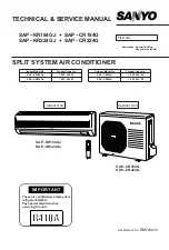
Indoor Unit
Outdoor Unit
SPLIT SYSTEM AIR CONDITIONER
AIR CONDITIONER
SAP – KR184GJ
SAP – KR224GJ
SAP – CR184G
SAP – CR224G
IMPORTANT
These air conditioners employ new
refrigerant R410A.
Pay special attention when
servicing the unit.
Indoor Model No.
Product Code No.
SAP – KR184GJ
1 852 094 05
SAP – KR224GJ
1 852 094 04
Outdoor Model No.
Product Code No.
SAP – CR184G
1 852 094 09
SAP – CR224G
1 852 094 08
Destination: Australia (50Hz)
General area (50Hz)