background image

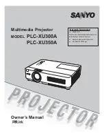
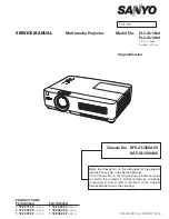
Multimedia Projector

SERVICE MANUAL

Product code 

Plc-xu350A                Plc-xu300A             

1 122 471 20


(KF5AE)        

1 122 461 20


(KA5AE)          

1 122 472 20


(LF5AE)        

1 122 462 20


(LA5AE) 

1 122 472 22


(LF5CE)        

1 122 462 22


(LA5CE)  

original Version

REFERENCE NO. 

SM

5111167-00

 FILE NO.

Model No.    

Plc-xu350A


Plc-xu300A


     U.S.A, Canada,                  

                               Europe, U.K, Asia

chassis No.  KF5-xu350A00
 

KA5-xu300A00

Match the Chassis No. on the rating label of the projector 
with the Chassis No. in the Service Manual.
If the Chassis No. in the Original Service Manual does 
not  match  the  projector's,  additional  Service  Literature 
is  required. You  must  refer  to  "Notices"  to  the  Original 
Service Manual prior to the servicing.

Summary of Contents for PLC-XU300A

Page 1: ...M5111167 00 FILE NO Model No PLC XU350A PLC XU300A U S A Canada Europe U K Asia Chassis No KF5 XU350A00 KA5 XU300A00 Match the Chassis No on the rating label of the projector with the Chassis No in the Service Manual If the Chassis No in the Original Service Manual does not match the projector s additional Service Literature is required You must refer to Notices to the Original Service Manual prio...

Page 2: ...ssembly 18 Adjustments 24 Adjustments after Parts Replacement 24 Optical Adjustments 25 Contrast adjustment 25 Integrator lens adjustment 26 Relay lens Out adjustment 27 Electrical Adjustments 28 Service Adjustment Menu Operation 28 Memory IC IC1371 Replacement 28 Circuit Adjustments 29 Test Points and Locations 34 Service Adjustment Data Table 35 Chassis Block Diagrams 52 Chassis over view 52 Sys...

Page 3: ...ore replacing the cabinet cover thoroughly inspect the inside of the cabinet to see that no stray parts or tools have been left inside Before returning any projector to the customer the service personnel must be sure it is completely safe to operate without danger of electric shock Service Personnel Warning Eye damage may result from directly viewing the light produced by the Lamp used in this equ...

Page 4: ... Frequency H sync 15 kHz 100 kHz V sync 50 100 Hz Optical Information Projection Image Size Diagonal Adjustable from 40 to 300 Throw Distance 4 6 41 7 1 4 m 12 7 m Projection Lens F 1 60 1 76 lens with f 22 3 mm 26 8 mm with manual zoom and focus Projection Lamp 225 W Interface Video Input Jack RCA Type x 1 S video Input Jack Mini DIN 4 pin x 1 Audio Input Jacks RCA Type x 2 Computer 1 Computer 2 ...

Page 5: ...C the thermal switch returns automatically This projector provides the following circuit protections to operate in safety If the abnormality occurs inside the pro jector it will automatically turn off by operating one of the following protection circuits Thermal switch SW902 Fuse Circuit Protections Lamp cover switch SW901 Fuse A fuse is located inside of the projector When the POWER indica tor is...

Page 6: ...tions in the Air filter care and cleaning below Ventilation slots of the projector are blocked In such an event reposition the projector so that ventilation slots are not obstructed Check if projector is used at higher temperature place Normal operating temperature is 5 to 35 C or 41 to 95 F Warning temperature and power failure protection The projector is shut down and the WARNING indicator light...

Page 7: ...age in these envi ronments may cause poor image quality When using the projector under dusty or smoky conditions dust may accumulate on a lens LCD panels or optical elements inside the projector degrading the quality of a projected image When the symptoms above are noticed contact your authorized dealer or service station for proper cleaning Cleaning the Air Filter Maintenance Filters Note When re...

Page 8: ...rcially available air blower to clean the lens Avoid using an excessive amount of cleaner Abrasive cleaners solvents or other harsh chemicals might scratch the surface of the lens Cleaning the Projection Lens Unplug the AC power cord before cleaning Gently wipe the projector body with a soft dry cleaning cloth When the cabinet is heavily soiled use a small amount of mild detergent and finish with ...

Page 9: ...lamp is set properly Push the lamp cover and secure the screw 4 Loosen the screw and open the lamp cover 2 Connect the AC power cord to the projector and turn on the projector 5 Procedure For continued safety replace with a lamp of the same type Do not drop a lamp or touch a glass bulb The glass can shatter and may cause injury Allow a projector to cool for at least 45 minutes before you open the ...

Page 10: ...mendation Should the air filter become clogged with dust particles it will reduce the cooling fan s effectiveness and may re sult in internal heat build up and short lamp life We recommend cleaning the air filter after the projection lamp is replaced Refer to Air Filter Cleaning Counter Projector 450H Lamp Normal 200H Eco 250H Corresponding value 500H Total lamp used time Projector used time Count...

Page 11: ...to an AC outlet again 3 Keep pressing the SELECT button and then press the ON STAND BY button 4 Release the ON STAND BY button first and then release the SELECT button The PIN code lock and Logo PIN code lock will be reset as the initial PIN code at the factory and the key lock function is disabled Please refer to the owner s manual for further information of the security functions Function Descri...

Page 12: ...jector status while the projector is powered off Eco Select Eco when you do not use the projector via network The projector s network function will stop when turning off the projector When Eco is selected several functions will be restricted Power consumption when standing by increases in the state of Network Restricted Function at the Eco mode Standby mode Notice Function Eco mode Serial command ...

Page 13: ...ance and product safety Screws Expression Type Diameter x Length mm T type M Type B M3x8 x5 R C Board Fig 1 Cabinet top D T3X8 x3 1 Loose screw A M3x8 to remove the Lamp Cover 2 Remove 5 screws B M3x8 to remove the Cabinet Top 3 Remove the Control Buttons and Dec Inlay LED 4 Remove 3 screws C M3x6 and screws D T3x8 to re move the Cabinet Front 5 Remove screw E T3x6 to remove the R C Board 6 Remove...

Page 14: ... 2 Release the hooks to remove the AV Panel and remove 3 screws C T3x6 to remove the AV Board 3 Remove 3 screws D T3X8 to remove the fans FN902 and FN906 Fig 2 2 Main Board AV Panel and Fan removal A M2 5x6 x5 A A A A B M4x4 x2 B Main Board C T3x6 x3 C C AV Board Hooks D T3x8 x3 Fan FN902 Fan FN906 SW901 D D ...

Page 15: ...emove the CONNECT ID board 5 Remove the screw F T3x8 to disconnect the Ballast socket 6 Remove 5 screws G T3x8 and 3 screws H T3x8 to remove the Optical Unit and the Lamp holder Fig 3 3 Speaker SP901 Fan FN901 Lamp Unit LP900 and Optical Unit removal Optical Unit Ballast socket Speaker SP901 E T3x6 x2 Lamp LP900 D M3x7 X3 CONNECT ID board Lamp holder D D E F T3x8 A T3x8 X2 A Speaker holder G T3x8 ...

Page 16: ...rd 1 Remove 3 screws A T3x8 screw B M3x8 and 3 screws C M4x4 to remove the power board shield 2 Remove the 2 screws D T3x8 to remove the Ballast board 3 Remove the power board holder Loose the hooks to remove the Power board C M4x4 x3 A B M3x8 A Power board shield C C D Power board holder Power board holder Hooks Hooks ...

Page 17: ...t bottom and fan FN904 2 Remove 2 screws D T3x12 to remove the fans FN903 and FN905 3 Remove screw E T3x8 and screw F M3X8 to remove the Left side shield 4 Remove 2 screws G T3x8 to remove the filter board 5 Remove the Air filters A M4x4 C T 3x6 x4 FN905 FN903 FN904 Mounting duct bottom Mounting duct top Air filter A B T3x12 x2 B C C C D T3x12 x2 D Air filter base Filter Board spacer sheet Air fil...

Page 18: ... 0mm hex wrench 1 Projection lens disassembly M2 5x6 x4 Fig 1 2 Integrator lens in disassembly Integrator lens in Integrator Lens In Ass y M 2 5x6 Fig 2 Rugged surface Front Projection lens Optical unit Note The optical unit should be removed from the cabinet bottom before re moving the projection lens M3x14 x2 Prism Beam Splitter PBS Integrator lens out Rugged surface Rear ...

Page 19: ...ading at the top bottom left or right of the screen If there is try to remove the shading following to the chapter Optical Adjustment Check the white balance If it needs the adjustment adjust the white balance following to the White Balance adjustment Gamma adjustment and Common Center adjustment in the chapter Electrical Adjustment Check the white uniformity on the screen If you find the color sh...

Page 20: ... for the replaced LCD Panel Prism Ass y The gamma characteristics is different between L Type and R Type LCD Panel Prism Ass y How to check the type of LCDPanel Prism Ass y Check the printed number on the flat cable of the G LCD Panel Fig 3 2 PanelType Check L3P06X 86G20 a03CA142I8 86G20 L3P06X 85G20 a00ca146I8 85G20 G LCD PANEL L Type LCD Panel Prism Ass y R Type LCD Panel Prism Ass y For PLC XU3...

Page 21: ...ed glass Pre polarized glass removal Pre Polarized Glass G Mount the polarized glasses as the film attached side faces the LCD panel side M2x4 Film Blue Red Green Fig 5 Polarized Glass G Polarized Glass R Polarized Glass B M2x4 M2x4 Pre Polarized Glass B Pre Polarized Glass R Note There is no Pre Polarized Glass R for KA5 XU30000 ...

Page 22: ... 22 Optical Parts Disassembly 6 Optical unit top removal Fig 6 Optical top 7 Relay lens disassembly Relay lens Relay lens Ass y Fig 7 M 2 5x6 ...

Page 23: ... 1 Integrator lens IN 2 Integrator lens OUT 3 Prism beam splitter PBS 4 Condenser lens OUT 5 Dichroic mirror B 6 Dichroic mirror G 7 Condenser lens G 8 Mirror R 9 Relay lens IN 10 Condenser lens R 11 Condenser lens B 12 Mirror B 8 Film attached side is facing this side 8 3 Rugged surface is facing this side Point marker is printed on this side Point marker is printed on this side Point marker is p...

Page 24: ...t adjustment Integrator lens adjustment Relay lens out adjustment Electrical Adjustments Fan control adjustment Reference voltage adjusment Panel type check and setting Auto calibration adjustment PC Auto calibration adjustment Component Auto calibration adjustment Video Common center adjustment 50 white adjustment PC White balance adjustment PC 50 white adjustment Video White balance adjustment V...

Page 25: ...the Mechanical Disassembly Adjustments require a 2 0mm hex wrench and a slot screwdriver When you adjust Integrator lens or Relay lens adjustment you need to disconnect FPC cables of LCD panels on the main board Optical adjustment requires a 2 0mm hex wrench and a slot screwdriver Note Do not disconnect connectors on the main board because the projector cannot turn on due to operate the power fail...

Page 26: ...n 1 screw A and adjust the slot B to make color uniformity in white by using a slot screwdriver 2 If the shading appears on the top or bottom of the screen as shown in Fig 2 2 loosen 2 screws C and adjust the slots D to make color uniformity in white by using a slot screwdriver 4Tighten screws A and C to fix the Integrator lens unit Note The relay lens adjustment must be carried out after completi...

Page 27: ...nifor mity in white If the shading appears on the left or right of the screen as shown in Fig 3 loosen 1 screw A by using a hex screwdriver and adjust the slot B to make color uniformity in white by using a slot screwdriver 4Tighten the screw A to fix the relay lens unit Relay lens Out adjustment Optical Adjustments Moving of slot B a b Fig 3 A Slot B b a White ...

Page 28: ...res the data for the service adjustments and should not be replaced except for the case of defective device If replaced the re adjustments are required following to the Electrical Adjustments Caution to memory IC replacement When memory IC is replaced with new one the CPU writes down the default data of the service adjustments to the replaced IC as the mentioned on the service ad justment table As...

Page 29: ...of UV radiation those adjustments must be completed within 25 minutes Adjustment Condition Input signal Video signal 1 0Vp p 75W terminated 16 steps gray scale Composite video signal Component Video signal 1 0Vp p 75W terminated 8 color 100 color bar or 16 step gray scale Component video signal Computer signal 0 7Vp p 75W terminated 16 steps gray scale pattern Image control mode STANDARD mode unle...

Page 30: ...tem no 14 to adjust the voltage of TP35G to make the amplitude D Vpp to be 10 00 0 05V 3 Reference Voltage Adjustment 㪛㩷㪲㪭㫇㫇㪴 Before setting you need to check which type of LCD panel is placed on the projector according to the item LCD Panel Prism Ass y removal in the chapter Optical Parts Disassembly 1 Enter the service mode 2 Panel Type Check Select group no 290 item no 0 Check the data value as...

Page 31: ... select group no 260 item no 0 and then change data value from 0 to 1 After the auto calibration com pleted OK will appear on the screen 4 Auto Calibration adjustment PC Below adjustments are performed when the above auto calibration is failed Pedestal adjustment Component 1 Enter the service mode 2 Receive the 16 step grey scale 480i component signal with Computer2 Component mode 3 Connect an osc...

Page 32: ...nent to the screen 7 Select item no 0 and change data value to obtain the minimum flicker on the screen 8 Project only blue light component to the screen 9 Select item no 2 and change data value to obtain the minimum flicker on the screen 10 Select group no 100 item no 92 and change data value to 0 to reset the panel frequency 7 Common Center adjustment 1 Enter the service mode 2 Receive the 16 st...

Page 33: ...3 By pressing the SELECT button the Keystone Offset adjustment will start 4 When it has completed the OK message will appear on the screen 5 By pressing any button on the projector or the remote control the OK message will disappear Data value of Group no 102 item no 3 will be back from 5 to 0 for initial value 12 Keystone Offset adjustment If the correction of the Color shading adjustment is nec ...

Page 34: ... 34 Electrical Adjustments K10B K10C K9602 IC5001 IC501 IC531 IC9885 K8B K8E K8G K8J K8K K8P K8I K8D K8H K5G K5R K5B K10C TPFANC TPFANB TP35B TPFANA TP35R TP35G MAIN BOARD Test Points and Locations ...

Page 35: ...mponent SCART SyncOn Green Threhould 6 3 2 0 15 11 SOGHYSDIS PC Component SCART Sync On Green Hsysterisis Enable 0 0 1 12 HS1TH 4 0 7 13 HS0TH 4 0 7 100 PreCoast PC Signal 3 0 63 101 PostCoast PC Signal 8 0 63 120 PreCoast PC Video 480i 7 0 63 121 PostCoast PC Video 480i 13 0 63 122 PreCoast PC Video 575i 7 0 63 123 PostCoast PC Video 575i 13 0 63 124 PreCoast PC Video 480p 7 0 63 125 PostCoast PC...

Page 36: ...in 10 10 0 255 Composite S Video Gain Adjustment Video 1 C Level Composite S Video C Level ADC Saturation 115 115 0 255 Composite S Video 2 3 XCXL Level Cross Chroma Cross Luma Level 3 0 5 4 C2DNBANDWIDTH Comb 2D Narrow Bandwidth 3 3 0 3 NTSC PAL 5 C2DWBANDWIDTH Comb 2D Wide Bandwidth 4 4 0 7 NTSC PAL 6 C2DCNMINLEAK Comb 2D Chroma Narrow Band Minimum Leakage 0 3 0 3 Left Values are adjustable if C...

Page 37: ...R L1 0 Noise Pixel Range NSRANGEY NSRANGEUV 1 0 2 1 Noise Region 0 NSREGIONY0 NSREGIONUV0 12 0 1023 2 Noise Region 1 NSREGIONY1 NSREGIONUV1 24 0 1023 3 Noise Region 2 NSREGIONY2 NSREGIONUV2 40 0 1023 4 Noise Gain Level NSFILTERY NSFILTERUV 50 0 255 Group 49 Noise Reduction Time Effective only for N R L2 0 Noise Pixel Range NSRANGEY NSRANGEUV 1 0 2 1 Noise Region 0 NSREGIONY0 NSREGIONUV0 12 0 1023 ...

Page 38: ...1000 7 Alpha Color 70 70 70 70 70 70 0 1000 8 Alpha Tint 10 10 10 10 10 10 0 1000 9 Alpha Sharpness 10 10 10 10 10 10 0 1000 Group 100 Panel Service 0 G SubGain 2048 2064 2000 2000 1950 1950 1830 1900 0 4095 PCStandard PCDynamic PCReal PCBlackBoard AVStandard AVDy namic AVCinema AVBlackBoard 1 R SubGain 2048 2064 2000 2000 1850 2048 1950 2048 0 4095 2 B SubGain 2048 2064 2000 2000 2048 2000 2048 2...

Page 39: ...MAX Cyclic Operation 63 BlockG2 0 0 2047 MIN MAX Cyclic Operation 64 BlockB2 0 0 2047 MIN MAX Cyclic Operation 65 ReverceR 0 0 2047 MIN MAX Cyclic Operation 66 ReverceG 0 0 2047 MIN MAX Cyclic Operation 67 ReverceB 0 0 2047 MIN MAX Cyclic Operation 68 BackCrossR Cent 0 0 2047 69 BackCrossR Start 128 0 255 70 BackCrossR End 128 0 255 71 BackCrossG Cent 0 0 2047 72 BackCrossG Start 128 0 255 73 Back...

Page 40: ...DCOffset N4 0 0 0 2047 Scan Direction Front Rear 134 B DCOffset N5 0 0 0 2047 Scan Direction Front Rear 135 B DCOffset N6 0 0 0 2047 Scan Direction Front Rear 136 B DCOffset N7 0 0 0 2047 Scan Direction Front Rear 137 B DCOffset N8 0 0 0 2047 Scan Direction Front Rear 138 B DCOffset N9 0 0 0 2047 Scan Direction Front Rear 139 B DCOffset N10 0 0 0 2047 Scan Direction Front Rear 140 B DCOffset N11 0...

Page 41: ... 14 0 1023 XU300A XU350A 197 G_V_INPUT_SETP_1536 12 10 0 1023 XU300A XU350A 198 G_V_INPUT_SETP_2048 7 4 0 1023 XU300A XU350A 199 G_V_INPUT_SETP_2560 1 0 0 1023 XU300A XU350A 200 G_V_INPUT_SETP_3072 1020 1019 0 1023 XU300A XU350A 201 G_V_INPUT_SETP_3584 1018 1016 0 1023 XU300A XU350A 202 G_V_INPUT_SETP_4096 1016 1013 0 1023 XU300A XU350A 203 B_V_INPUT_SETP_0 24 22 0 1023 XU300A XU350A 204 B_V_INPUT...

Page 42: ...reshold value 230 0 255 2 Max value 21 0 255 3 Value per unit time 3 0 50 4 Time per 1step 1 1 30 5 Realtime APL RO 1 255 Group 200 Option 0 Logo Prohibition Forced No Brand Logo Prohibition 0 Menu 1 Forced 2 China 3 9 not used 0 0 2 Effective after AC On 1 RS232C Baudrate Baud Rate 0 0 2 0 19200bps 1 9600bps 2 115200bps 2 PJLink Enable PJLink 0 0 1 0 Disable 1 Enable 4 CABLE SW Long Cable 0 0 10 ...

Page 43: ... 0 1 0 Disable Service Adjustment Dsiable Used all the Center Values 1 Enable Service Adjustment Enable 6 Zoom Accelerator Enable 0 0 1 0 Zoom Accelerator OFF 1 Zoom Accelerator ON No last memory 7 DZoom Reset by Keystone 0 0 1 0 Enable Normal 1 Disable Dzoo is not cancelled even if Keystone is cancelled No last memory 8 Stability Count Count Value of V missing 5 0 255 9 Sensivity for Signal Lost ...

Page 44: ...mmer level High 15 0 15 Group 231 VBI Slice Level 0 Generic Initial Slicing Level PW190 register 0xE344 0x34 0 255 1 Generic High Level Threshold PW190 register 0xE345 0 255 2 Generic Low Level Threshold PW190 register 0xE346 0 255 3 Generic Minimum Low Level PW190 register 0xE347 0x30 0 255 4 Generic Maximum High Level PW190 register 0xE348 0xe0 0 255 Group 250 FAN Control 0 FAN1 MIN ADJUST DAC D...

Page 45: ...tage Normal Ceiling HiLand Normal HiLand Ceiling 10 Normal Fan Control MinTemp Temp Senser Control Start End Tem p at Normal 33 33 35 35 20 100 11 Normal Fan Control Max Temp 38 39 39 39 20 100 12 Normal Fan1 Min Fan voltage value at Normal unit 0 1V 72 77 95 95 0 255 13 Normal Fan1 Max 125 125 125 125 0 255 14 Normal Fan2 Min 68 75 85 90 0 255 15 Normal Fan2 Max 80 80 80 80 0 255 16 Normal Fan3 M...

Page 46: ...0 1 OFFSET AREA V START Black Level Acquiring Area V Start Position 500 0 1000 2 GAIN AREA H START White Level Acquiring Area H Start Position 25 0 1000 3 GAIN AREA V START White Level Acquiring Area V Start Position 500 0 1000 4 Image AREA H WIDTH Black White Level Acquiring Area 13 0 4095 5 Image AREA V HIGHT Black White Level Acquiring Area Height 9 0 4095 6 OFFSET target Target Value of Black ...

Page 47: ...USTOM Aspect 0 Scaler Horizontal Horizontal Scaler Edit 100 68 132 1 Sclaler Vertical Vertical Scaler Edit 100 68 132 2 Connect Seperate Connect Edit 0 0 1 0 Seperate 1 Connect 3 Position Horizontal Horizontal Postion Correction 100 85 115 4 Position Vertical Vertical Position Correct 100 85 115 5 Aspect Enable Aspect Adj Enable 0 0 1 1 Enable 0 Disable Group 280 AutoPC Adjust 0 AutoPCAdjustEnable...

Page 48: ...48 0 4095 4 Disp Line 458 0 4095 Group 521 YCbCr 575i 0 Total Dots 864 0 4095 1 Disp Dots 656 0 4095 2 H Back Porch 162 0 4095 3 V Back Porch 64 0 4095 4 Disp Line 534 0 4095 Group 522 YCbCr 480P 0 Total Dots 858 0 4095 Read only 1 Disp Dots 684 0 4095 2 H Back Porch 136 0 4095 3 V Back Porch 46 0 4095 4 Disp Line 460 0 4095 Group 523 YCbCr 575P 0 Total Dots 864 0 4095 Read only 1 Disp Dots 690 0 ...

Page 49: ...ack Porch 166 0 4095 3 V Back Porch 48 0 4095 4 Disp Line 460 0 4095 5 Clamp 1 0 255 6 Clamp Width 31 0 255 Group 541 RGB Video 575i 0 Total Dots 966 0 4095 1 Disp Dots 736 0 4095 2 H Back Porch 182 0 4095 3 V Back Porch 66 0 4095 4 Disp Line 536 0 4095 5 Clamp 1 0 255 6 Clamp Width 31 0 255 Group 542 RGB Video 480P 0 Total Dots 960 0 4095 1 Disp Dots 766 0 4095 2 H Back Porch 156 0 4095 3 V Back ...

Page 50: ...260 0 4095 3 V Back Porch 54 0 4095 4 Disp Line 1052 0 4095 5 Clamp 1 0 255 6 Clamp Width 31 0 255 Group 548 RGB Video 1035i 0 Total Dots 2200 0 4095 2 H Back Porch 258 0 4095 3 V Back Porch 92 0 4095 4 Disp Line 1012 0 4095 Group 560 HDCP 480P 7 Over Scan Over Scan Rate 0 25 5 at 0 1 steps 0 0 255 8 VSBEG 2 0 15 Group 561 HDCP 575P 7 Over Scan Over Scan Rate 0 25 5 at 0 1 steps 0 0 255 8 VSBEG 2 ...

Page 51: ...r Scan Rate 0 25 5 at 0 1 steps 0 0 255 8 VSBEG 2 0 15 Group 981 Color Shading Adj Offset 0 R Max 0 0 0 255 1 R Mid1 0 0 0 255 2 R Mid2 0 0 0 255 3 R Min 0 0 0 255 4 G Max 0 0 0 255 5 G Mid1 0 0 0 255 6 G Mid2 0 0 0 255 7 G Min 0 0 0 255 8 B Max 0 0 0 255 9 B Mid1 0 0 0 255 10 B Mid2 0 0 0 255 11 B Min 0 0 0 255 ...

Page 52: ...ASLHTRJ IC3852 LA6358NM POWER UNIT 16V 6V 7V SP 1W FANCon FAN 6 S VIDEO VIDEO A udioǂOUT L3E07111K Digital Gamma ǂ B L3E06170P0A ǂ G L3E06170P0A ୄ R L3E06170P0A VIDEO Audio IN IC801 FLASH ROM EEPROM RJ45 A 1 22 A 1 22 Lamp ID IC8801 LAN Control QXXAVD059 M COMPUTER 1 Audio IN COMPUTER 2 Audio IN PCI IN RGB YCbCr SCART Anlalog SW Buffer PCI IN Monitor Out IC401 IC301 R C LAMP BALLASR LED KEY_SW IC9...

Page 53: ...PW SCL1 SDA1 SCL2 SDA2 188 214 RXD_PW 386 TXD_PW 124 211 294 SCL0 SDA0 293 212 290 208 FAN_CON_A 30 FAN_CON_B 128 IC301 SYSTEMCONTROL D6835 Q5035 ON H LAMP_LED D6833 D6831 Q6846 Q6845 LAMP REPLACE WARNING POWER IC4891 NAND 2 13 1 10 IC9882 INVERTER 2 K6R K8S 3 1 K8H 4 5 1 K8D K29D 3 S3 3V FAN CONTROL CIRCUIT KEY SWITCH SCL2_5V SDA2_5V 9 K8F 1 3 LAMP_DET FAN_CON_C 373 PW_MASTER_SDO 96 PIC_LAMP_LED ...

Page 54: ...E FILTER A901 LAMP BALLAST SW901 LAMP COVER SW LAMP_DET IC9882 INVERTER 13 10 89 2 5 4 1 1 3 K8R K6R K8H K8S 1 2 POWER ON H MAIN POWER Power Control LAMP_DET 285 14 9 8 7 21 15 16 IC4891 FAN ERR 4 1 2 CHO_TXD CHO_RXD LAMP_SCI PW_MASTER_SDO PW_MASTER_SDi PW_MASTER_SCK LAMP_PWM_A Lamp control ...

Page 55: ...MAIN IC1303 BUS SW SPEAKER SP901 L R L R 5 17 7 15 10 9 4 1 2 20 AUDIO OUT L R 7 15 3 5 2 6 Q5031 K300 K200 Q5061 Q5063 Q5035 IC5031 LM4889 AUDIO OUT 1 3 K8F IC301 SCALER SCL2_5V OUT_DET SDA2_5V SCL2_5V SDA2_5V 208 290 344 AUDIO MUTE MUTE Mute On H L R 6 16 PC AUDIO1 IN 5 8 Audio circuit ...

Page 56: ...V S16V S 7V ON_15V LAMPDC_ON IC4891 NAND S6V S16V S 7V 9 8 6 5 3 IC8831 TEMP SENSOR3 MCP9801 LAMP PANEL OUT SIDE IC8821 TEMP SENSORƝ MCP9801 IC8811 TEMP SENSOR1 MCP9801 LAMP_DET 285 14 16 15 2 13 215 11 201 ON_5V 110 Power On H ON_1 8V 363 LAMP_DC_ON 89 293 212 SCL0 SDA0 IC9885 SUB CPU SW901 S16V FAN_A Q7812 D3613 D591 D592 2 IC5621 S1 8V_PW IC5821 S2 5V_PW IC5841 S1 8V IC5861 IC5081 15V_PNL FAN_C...

Page 57: ...K8J FN902 1 2 D3627 IC8821 TEMP SENSOR2 MCP9801 2 1 IC8831 TEMP SENSOR3 MCP9801 IC9885 SUB CPU IC8811 TEMP SENSOR1 MCP9801 MAIN BOARD FAN_CON_C FAN_CON_A IC301 SYSTEM CONTROL IC4891 NAND 1 4 215 Q7801 2 FAN_SW1 Power On H 190 FAN_CON_B 128 293 212 SCL0 SDA0 Power Error On P_Fail H SIGNAL MODE POWER ON STAND BY H L NORMAL ERROR H L FAN_SW1 P_FAIL P_FAIL FAN_ERR TPFANB K8S K8H K8D 3 6 5 1 1 2 LAMP_S...

Page 58: ...IC8831 TEMP Sensor 3 K29D K8D RC MAIN 6 SCL1 SDA1 211 294 5 IC1371 CONTROL MEMORY 2 1 IC8821 TEMP Sensor 2 IC8811 TEMP Sensor 1 ADT75BRMZ 4 3 SCL2 SDA2 IC1303 IIC Buffer 6 290 3 SCL2_5V SDA2_5V IC5001 AUDIO CONTROL NJW115 IC1422 DAC M62334FPP 7 6 208 IIC bus Control circuit ...

Page 59: ...until cool ing is completed and the POWER indicator stops blinking Q The projector is ready to be turned on with the POWER ON OFF button Q The projector is operating normally Q The projector is in the Power management mode Q The temperature inside the projector is abnormally high The pro jector cannot be turned on When the projector is cooled down enough and the temperature returns to normal the P...

Page 60: ...AIL_LAN is sent to pin 370 of IC301 SYSTEM CONTROL when the abnormality occurred inside the projector and then the IC301 sends the shutdown signal LAMP_DC_ON to the power supply circuit to stop its operation and signal LAMP_SCI to the lamp ballast board via IC4891 and SW901 lamp cover switch to stop operation of the lamp circuit An abnormality occurs on the secondary power supply Check power suppl...

Page 61: ... stage and processing stage Check IC301 Scaler and peripheral circuit No picture with all of computer input sources Yes Yes No No No No Check AV source selecting and decoding stage S Video source Check S video signal Y C S_CHROMA signal is applied to pin 265 of IC301 Scaler and S Y signal is applied on pin 264 of IC301 S_SW signal S VIDEO L is input to pin 267 of IC301 Scaler Composite video sourc...

Page 62: ...udio output circuit Check speaker connection of the terminal K8F Yes No Check IC5031 IC5081 and peripheral circuit Check the Mute signal at pin 5 of Q5035 The Mute signal is output from pin 344 of IC 301 Scaler The OUT_DET signal is sent from Audio Out terminal Mute On H at pin 344 of IC301 L at pin 1 of IC5031 Check if the audio signal is observed at pins 5 and 8 of IC5031 Yes No ...

Page 63: ...ADC0 P_FAIL Power Failure Signal Input Failure L I 126 D25 ADC2 ADC2 KEY 2 Key Control Input I 29 D26 ADC6 ADC6 LAMP Option Lamp Option I 362 E14 PORTC4 IRM_RST L3E07111 reset O 368 E20 PORTH0 RXD_PW Serial Control RXD I 370 E22 ADC5 ADC5 P_FAIL_LAN LAN error detect I 30 E26 DAC1 DAC1 FAN_CON_A FAN CON_A O 298 F23 ADC4 ADC4 BRAND Option Option Switch BRAND I 128 F25 DAC2 DAC2 FAN_CON_B FAN CON_B O...

Page 64: ... 64 IC Block Diagrams FA5550NG P F Control IC621 XR16L5701IL24 UART IC9885 ...

Page 65: ... 65 IC Block Diagrams MAX232ECPWRP RS 232C Driver IC3801 L3E06170 D A S H LCD Driver IC501 IC531 IC561 ...

Page 66: ...㻲㻸㻷㻾㻔㻔㻝㻓㼀 㻪㻕㻲㻸㻷㻾㻔㻔㻝㻓㼀 㻥㻕㻲㻸㻷㻾㻔㻔㻝㻓㼀 㻲㻶㻧㻵㻬㻱㻾㻔㻝㻓㼀 㻲㻶㻧㻥㻬㻱㻾㻔㻝㻓㼀 㻲㻶㻧㻶㻺 㻲㻶㻧㻪㻬㻱㻾㻔㻝㻓㼀 㻶㻦㻯㻮 㻶㻧㻤㻷㻤 㻶㻦㻶 㻹㻶㻼㻱㻦 㻫㻶㻼㻱㻦 㻧㻦㻯㻮 㻶㻨㻯㻨㻦㻷 㻦㻯㻻㻲㻸㻷㻋㻵㻝㻪㻝㻥㻌 㻧㻻㻲㻸㻷㻋㻵㻝㻪㻝㻥㻌 㻫㻵㻨㻶㻨㻷㻲 㻫㻳㻯㻯 㻹㻵㻨㻶㻨㻷㻲 㻦㻯㻼㻲㻸㻷 㻧㻼㻲㻸㻷 㻩㻵㻳㻋㻵㻝㻪㻝㻥㻌 㻶㻫㻦㻯㻮㻋㻵㻝㻪㻝㻥㻌㻱 㻶㻫㻦㻯㻮㻋㻵㻝㻪㻝㻥㻌 㻻㻩㻵㻋㻵㻝㻪㻝㻥㻌 㻶㻷㻶㻴㻨㻋㻵㻝㻪㻝㻥㻌 㻶㻷㻶㻴㻲㻋㻵㻝㻪㻝㻥㻌 㻱㻵㻪 㻶㻫㻨㻱㻥 㻦㻯㻳㻔䡐㻕 㻧㻬㻵㻼 㻨㻱㻥㻼㻔㻐㻕 㻨㻱㻥㻻㻔㻐㻗㻋㻵㻝㻪㻝㻥㻌 㻰㻶㻨㻯㻋㻵㻝㻪㻝㻥㻌 㻧㻨㻋㻵㻝㻪㻝㻥㻌 㻶㻵㻦㻶 㻶㻵㻧㻤㻷㻤 PIC16F688T LAMP ID IC8741 ...

Page 67: ... 67 IC Block Diagrams NJW1156 Audio Control IC5001 6 16 16 16 16 16 7 47 4 16 4 16 4 16 4 16 4 16 4 7 7 7 16 1 1V MZNIKM PW190 Scaler IC301 ...

Page 68: ... 68 IC Block Diagrams MR4010 Power OSC IC631 PIC18F67J60 LAN CONTROL IC8801 ...

Page 69: ... 69 IC Block Diagrams FA7703 DC DC Converter IC7811 ...

Page 70: ...llized Composite STYRENE Styrene TA SOLID Tantalum Oxide Solid Electrolytic AL SOLID Aluminium Solid Electrolytic ELECT Aluminum Foil Electrolytic NP ELECT Non polarised Electrolytic OS SOLID Aluminium Solid with Organic Semiconductive Electrolytic POS SOLID Polymerized Organic Semiconductive DL ELECT Double Layered Electrolytic PPS FILM Polyphenylene Sulfide Film MT PPS FILM Metalized Polyphenyle...

Page 71: ...Out Of Circuit Board A1000 Main Board A901 Ballast Board A601 Power Board FN903 Cooling Fan FN906 Cooling Fan LP900 Lamp Ass y FN905 Cooling Fan SP901 Speaker FN901 Cooling Fan FN904 Cooling Fan SW902 Thermal Switch A8700 CONNECT ID Board A1001 AV Board A602 Filter Board FN902 Cooling Fan SW901 Lamp Cover Switch ...

Page 72: ...C 1000P K 1K 304 084 6300 CERAMIC 1000P K 1K C613 303 451 4119 MT POLYEST 1U K 450V C614 303 451 4119 MT POLYEST 1U K 450V C615 404 118 3609 ELECT 150U M 420V C621 303 336 3510 CERAMIC 0 47U K 16V 403 459 8017 CERAMIC 0 47U K 16V 304 110 9800 CERAMIC 0 47U K 16V C622 304 091 4504 CERAMIC 0 047U K 50V C623 304 090 1207 CERAMIC 0 01U K 50V C625 304 090 1207 CERAMIC 0 01U K 50V C626 303 396 9613 CERA...

Page 73: ...4 GB TP7 PC663 307 223 7315 PC TLP421F D4 GB TP4 307 223 8312 PC TLP421F D4 GR TP4 407 265 7813 PC TLP781F D4 GB TP7 PC671 307 223 7315 PC TLP421F D4 GB TP4 307 223 8312 PC TLP421F D4 GR TP4 407 265 7813 PC TLP781F D4 GB TP7 PTH611 308 037 5501 THERMISTOR NTPDB5R0LDHB0 PTH641 408 062 4606 TH PRF18BD471QB1RB ZD631 307 206 5413 ZD UDZS TE 178 2B 655 003 4328 ASSY PWB FILTER KG5AE CAPACITOR C601 404 ...

Page 74: ...00 IC 24AA64T I MS IC1422 309 431 4424 IC M62334FP DF5Q IC1424 410 666 5804 IC UPC358GR 9LG E1 A IC301 309 670 8419 IC PW190 10L IC302 309 487 5727 IC TC7SZ125FU IC3801 409 699 2815 IC MAX232ECPWR IC3852 309 246 9710 IC LA6358NM TE L E IC4001 409 677 4619 IC EL5308IUZ IC4701 309 428 8428 IC TC7WT125FU TE12L IC4891 309 395 5915 IC TC7SH00FU TE85L IC5001 409 683 5716 IC NJW1156AV IC5031 309 594 1916...

Page 75: ... 403 478 5714 CERAMIC 10U K 25V C2004 303 358 3215 CERAMIC 10U K 6 3V 303 370 0018 CERAMIC 10U K 6 3V 303 368 7319 CERAMIC 10U K 6 3V C2011 303 453 8917 CERAMIC 0 1U K 16V 303 453 8610 CERAMIC 0 1U K 16V 303 409 3426 CERAMIC 0 1U K 16V C2012 303 453 8917 CERAMIC 0 1U K 16V 303 453 8610 CERAMIC 0 1U K 16V 303 409 3426 CERAMIC 0 1U K 16V C2021 303 358 3215 CERAMIC 10U K 6 3V 303 370 0018 CERAMIC 10U...

Page 76: ...303 453 8917 CERAMIC 0 1U K 16V 303 453 8610 CERAMIC 0 1U K 16V 303 409 3426 CERAMIC 0 1U K 16V C342 303 453 8917 CERAMIC 0 1U K 16V 303 453 8610 CERAMIC 0 1U K 16V 303 409 3426 CERAMIC 0 1U K 16V C343 303 453 8917 CERAMIC 0 1U K 16V 303 453 8610 CERAMIC 0 1U K 16V 303 409 3426 CERAMIC 0 1U K 16V C344 303 453 8917 CERAMIC 0 1U K 16V 303 453 8610 CERAMIC 0 1U K 16V 303 409 3426 CERAMIC 0 1U K 16V C...

Page 77: ...50V 303 276 3113 CERAMIC 33P J 50V C3548 303 453 7019 CERAMIC 33P J 50V 303 453 9617 CERAMIC 33P J 50V 303 276 3113 CERAMIC 33P J 50V C3549 303 453 7019 CERAMIC 33P J 50V 303 453 9617 CERAMIC 33P J 50V 303 276 3113 CERAMIC 33P J 50V C355 303 453 8917 CERAMIC 0 1U K 16V 303 453 8610 CERAMIC 0 1U K 16V 303 409 3426 CERAMIC 0 1U K 16V C3551 303 453 7019 CERAMIC 33P J 50V 303 453 9617 CERAMIC 33P J 50...

Page 78: ...RAMIC 0 1U K 16V 303 409 3426 CERAMIC 0 1U K 16V C370 303 453 8917 CERAMIC 0 1U K 16V 303 453 8610 CERAMIC 0 1U K 16V 303 409 3426 CERAMIC 0 1U K 16V C371 303 453 8917 CERAMIC 0 1U K 16V 303 453 8610 CERAMIC 0 1U K 16V 303 409 3426 CERAMIC 0 1U K 16V C372 403 457 2512 CERAMIC 0 47U K 10V 303 376 6311 CERAMIC 0 47U K 10V C373 403 457 2512 CERAMIC 0 47U K 10V 303 376 6311 CERAMIC 0 47U K 10V C374 40...

Page 79: ...AMIC 470P K 50V 303 282 5118 CERAMIC 470P K 50V C434 303 453 8917 CERAMIC 0 1U K 16V 303 453 8610 CERAMIC 0 1U K 16V 303 409 3426 CERAMIC 0 1U K 16V C436 303 453 8917 CERAMIC 0 1U K 16V 303 453 8610 CERAMIC 0 1U K 16V 303 409 3426 CERAMIC 0 1U K 16V C437 303 453 8917 CERAMIC 0 1U K 16V 303 453 8610 CERAMIC 0 1U K 16V 303 409 3426 CERAMIC 0 1U K 16V C438 303 454 0613 CERAMIC 0 01U K 50V 303 441 981...

Page 80: ...4 CERAMIC 2 2U K 25V C512 303 396 9613 CERAMIC 1U K 25V 303 397 7618 CERAMIC 1U K 25V 403 478 5912 CERAMIC 1U K 25V C513 303 396 9613 CERAMIC 1U K 25V 303 397 7618 CERAMIC 1U K 25V 403 478 5912 CERAMIC 1U K 25V C514 303 396 9613 CERAMIC 1U K 25V 303 397 7618 CERAMIC 1U K 25V 403 478 5912 CERAMIC 1U K 25V C516 303 396 9613 CERAMIC 1U K 25V 303 397 7618 CERAMIC 1U K 25V 403 478 5912 CERAMIC 1U K 25V...

Page 81: ... 1U K 16V C567 403 455 1616 CERAMIC 10U K 16V 403 478 5813 CERAMIC 10U K 16V C568 303 401 4312 ELECT 47U M 25V 303 419 5219 ELECT 47 0UM 25V C569 303 397 8219 CERAMIC 2 2U K 25V 403 454 6414 CERAMIC 2 2U K 25V C5705 303 376 3112 ELECT 100U M 25V C5706 303 453 8917 CERAMIC 0 1U K 16V 303 453 8610 CERAMIC 0 1U K 16V 303 409 3426 CERAMIC 0 1U K 16V C5707 303 324 6417 CERAMIC 0 022U K 16V C5708 303 39...

Page 82: ...C8806 303 453 8917 CERAMIC 0 1U K 16V 303 453 8610 CERAMIC 0 1U K 16V 303 409 3426 CERAMIC 0 1U K 16V C8807 303 453 7019 CERAMIC 33P J 50V 303 453 9617 CERAMIC 33P J 50V 303 276 3113 CERAMIC 33P J 50V C8808 303 453 7019 CERAMIC 33P J 50V 303 453 9617 CERAMIC 33P J 50V 303 276 3113 CERAMIC 33P J 50V C8809 303 453 8917 CERAMIC 0 1U K 16V 303 453 8610 CERAMIC 0 1U K 16V 303 409 3426 CERAMIC 0 1U K 16...

Page 83: ... R1424 301 225 1210 MT GLAZE 4 7K JA 1 16W R1425 301 294 3313 MT GLAZE 15K FA 1 16W R1426 301 299 5411 MT GLAZE 13K FA 1 16W R1427 301 224 8814 MT GLAZE 100 JA 1 16W R1428 301 224 8814 MT GLAZE 100 JA 1 16W R1435 301 294 4518 MT GLAZE 18K FA 1 16W R1444 301 235 0012 MT GLAZE 7 5K JA 1 16W R1446 301 235 0012 MT GLAZE 7 5K JA 1 16W R1447 301 225 1517 MT GLAZE 3 9K JA 1 16W R1448 301 224 9019 MT GLAZ...

Page 84: ...0 MT GLAZE 75 JA 1 16W R383 301 226 1516 MT GLAZE 0 000 ZA 1 16W R384 301 226 1516 MT GLAZE 0 000 ZA 1 16W R3856 301 226 1516 MT GLAZE 0 000 ZA 1 16W R3857 301 226 1516 MT GLAZE 0 000 ZA 1 16W R3858 301 226 1516 MT GLAZE 0 000 ZA 1 16W R3861 301 225 1210 MT GLAZE 4 7K JA 1 16W R3863 301 225 1210 MT GLAZE 4 7K JA 1 16W R3865 301 225 1210 MT GLAZE 4 7K JA 1 16W R3866 301 226 1516 MT GLAZE 0 000 ZA 1...

Page 85: ...ZA 1 16W R547 301 226 1516 MT GLAZE 0 000 ZA 1 16W R548 301 226 1516 MT GLAZE 0 000 ZA 1 16W R549 301 299 2410 MT GLAZE 5 6K FA 1 16W R5540 301 224 9316 MT GLAZE 1K JA 1 16W R5541 301 276 4710 MT GLAZE 0 000 ZA 1 3W R5542 301 224 9316 MT GLAZE 1K JA 1 16W R5543 301 276 4710 MT GLAZE 0 000 ZA 1 3W R560 301 226 1516 MT GLAZE 0 000 ZA 1 16W R5607 301 224 9316 MT GLAZE 1K JA 1 16W R561 301 224 8814 MT...

Page 86: ...10K JA 1 16W R7879 301 224 9316 MT GLAZE 1K JA 1 16W R7881 301 224 9316 MT GLAZE 1K JA 1 16W R7882 301 225 1210 MT GLAZE 4 7K JA 1 16W R7883 301 225 0213 MT GLAZE 3 3K JA 1 16W R7884 301 286 4717 MT GLAZE 30K JA 1 16W R801 301 224 9019 MT GLAZE 10K JA 1 16W R8039 301 341 0616 MT GLAZE 49 9 FA 1 16W R804 301 224 9019 MT GLAZE 10K JA 1 16W R8040 301 150 6014 MT GLAZE 0 000 ZA 1 10W R8049 301 341 061...

Page 87: ...NETWORK 0X4 1 16W RB502 945 036 3529 R NETWORK 0X4 1 32W 945 037 0817 R NETWORK 0X4 1 16W RB503 945 036 3529 R NETWORK 0X4 1 32W 945 037 0817 R NETWORK 0X4 1 16W RB504 945 036 3529 R NETWORK 0X4 1 32W 945 037 0817 R NETWORK 0X4 1 16W RB506 945 036 3529 R NETWORK 0X4 1 32W 945 037 0817 R NETWORK 0X4 1 16W RB507 945 036 3529 R NETWORK 0X4 1 32W 945 037 0817 R NETWORK 0X4 1 16W RB508 945 036 3529 R N...

Page 88: ...1 945 062 2855 INDUCTOR 33U M L8166 945 086 5368 IMPEDANCE 220 OHM P L8801 945 068 8318 FILTER EMI 100MHZ L8835 645 100 9340 IMPEDANCE 120 OHM P L8836 645 100 9340 IMPEDANCE 120 OHM P DIODE D1041 307 223 1115 ZENER DIODE 02DZ6 2Y TPH3 307 209 1214 ZD UDZS TE 176 2B D1042 307 223 1115 ZENER DIODE 02DZ6 2Y TPH3 307 209 1214 ZD UDZS TE 176 2B D1091 307 205 5216 DIODE RB521S 30 TE61 D1092 307 205 5216...

Page 89: ...1TX1 SW6803 945 026 2792 SWITCH PUSH 1P 1TX1 952 001 8830 SWITCH PUSH 1P 1TX1 SW6804 945 026 2792 SWITCH PUSH 1P 1TX1 952 001 8830 SWITCH PUSH 1P 1TX1 SW6806 945 026 2792 SWITCH PUSH 1P 1TX1 952 001 8830 SWITCH PUSH 1P 1TX1 SW6807 945 026 2792 SWITCH PUSH 1P 1TX1 952 001 8830 SWITCH PUSH 1P 1TX1 SW6808 945 026 2792 SWITCH PUSH 1P 1TX1 952 001 8830 SWITCH PUSH 1P 1TX1 SW6810 945 026 2792 SWITCH PUS...

Page 90: ... 003 4540 ASSY PWB ID CONNECT KF5AE RESISTOR R8738 301 226 1516 MT GLAZE 0 000 ZA 1 16W COIL L8731 945 086 6037 IMPEDANCE 330 OHM P L8732 945 086 6037 IMPEDANCE 330 OHM P L8733 945 086 6037 IMPEDANCE 330 OHM P L8734 945 086 6037 IMPEDANCE 330 OHM P L8737 945 086 6037 IMPEDANCE 330 OHM P PACKING MATERIALS 610 347 6933 CARTON CASE KF5AE For KF5 XU350A00 610 347 6940 CARTON CASE KA5AE For KA5 XU300A0...

Page 91: ...A00 91 Cabinet Parts Location M03 Mechanical Parts List C12 M06 C09 M01 C03 C05 C04 C02 C07 S01 M04 C08 S01 M07 C14 S01 C01 M02 C11 S02 S02 S03 C06 C16 C10 M08 M09 M10 M12 M11 S03 S03 S03 S03 C13 M16 M13 M14 M15 M17 M18 C15 ...

Page 92: ...KF5 XU350A00 KA5 XU300A00 92 Mechanical Parts List S05 S05 Optical Parts Location Integrator Lens In S04 Relay Lens Out L04 PBS L06 Relay out S04 L03 Integrator In L07 Integrator Out M05 ...

Page 93: ...KF5 XU350A00 KA5 XU300A00 93 Mechanical Parts List S05 S05 L14 Projection Lens Polarized Glass In Projection Lens S05 L02 R Polarized in R L02 G Polarized in G L02 B Polarized in B ...

Page 94: ...KF5 XU350A00 KA5 XU300A00 94 Mechanical Parts List L01 Prism LCD panel Ass y L01 R L01 Prism LCD Panel Assy Blue Red Green L01 G L01 B S07 S06 ...

Page 95: ...KF5 XU350A00 KA5 XU300A00 95 Mechanical Parts List L12 L05 L07 L08 L04 L09 L13 L11 L03 L10 In the Optical Unit L05 L12 L11 ...

Page 96: ...343 1345 MOUNTING DUCT LAMP TOP KG5AC M18 610 343 1376 MOUNTING DUCT LAMP BTM KG5AC SCREWS S01 411 077 8606 SCR TPG FLT 3X8 S02 411 189 8907 SCR BIN 4X4 S03 411 031 9304 SCR BIN 3X8 S04 411 189 8303 SCR BIN 3X14 S05 412 077 8108 SPECIAL SCREW 2 5X6 S06 411 190 9108 SCR BIN 2X4 S07 312 070 3400 SPECIAL SCREW 3 0X10V OPTICAL PARTS L01 610 344 3195 ASSY PNL PSM KG5AC Including Key No L01 R to L01 B L...

Page 97: ...KF5 XU350A00 KA5 XU300A00 97 Mechanical Parts List ...

Page 98: ... KF5AE KA5AE December 2009 DC 200 Printed in Japan SANYO Electric Co Ltd ...

Page 99: ...ervice manual original for chassis No KF5 XU350A00 KA5 XU300A00 models PLC XU350A and PLC XU300A File with the service manual No SM5111167 00 Note All the information of part numbers and values indicated on these diagrams are at the beginning of production To improve the performance there may be some differences to the actual set When you order the service parts use service parts code mentioned on...

Page 100: ...rk Material E Electrolytic P Electrolytic non polarized C Ceramic temperature compensation K Ceramic F Polyester N Polypropylene M Metalized polypropylene H Metalized polypromylar B Ceramic semiconductor G Metalized polyestel Y Composite film S Styrol T Tantalum oxide solid electrolytic U Organic semiconductive electrolyte D Electric double layer electrolytic Mark Tolerance A not specified B 0 1 C...

Page 101: ...J220 CGQ C631 10EM15005F C664 GND 25KK11D C626 K6R_1 GND 1SS355 D613 KK0 1LBYAG C671 C661_2 K6C_1A 1 10GF3 3KC R684 16EM4705D C665 KK0 047 LBYAG C622 EG01C D633 Z C 1 FB 2 GND 3 VCC 4 EM 5 7 Vin 9 CO 1 10GF2 7KC R674 TLP421F GBP PC671 TLP421F GRP TLP781F GBP 1 2 3 4 Z20051 L661 RF101L2SP D632 K6R_8 1 10GJ10KC R628 1 10GJ 10KC R643 C662_1 YG862C10MY D661 1 4GJ680KB R616 1 10GJ330C R662 ZZ0122 L631 ...

Page 102: ... X TPSI3 3V X C8028 X C8036 X R8094 SCDT S3 3VSI X L8006 X L8008 X C8031 X C8016 TPSIRST X C8003 X C8014 X R8008 X R8098 X C8027 S3 3VSI X C8026 X R8093 X RB8002 X R8712 X C8091 X L8002 X R8088 X C8033 5V_DVI X C8020 X C8081 X R8034 TPSIVS S3 3VSI1 SIRST X C8029 X C8019 P_FAIL 105 R1XC 58 Q19 106 R1X0 59 Q18 107 R1X0 108 R1X1 109 R1X1 60 DE 61 VSYNC 62 HSYNC 110 R1X2 63 CVCC12 111 R1X2 64 IOVCC33 ...

Page 103: ... VS2 GND L3BE221PG L312 VIDEO 1 16GZ0A R313 10KK0 47MN C372 16KK0 1MN C380 16KK0 1AYH 16KK0 1AXH GND SCL2 ON_1 8V S3 3VD_PW 1 16GZ0A R314 16KK0 1MN C328 16KK0 1AYH 16KK0 1AXH GND TR 16KK0 1MN C367 16KK0 1AYH 16KK0 1AXH 10KK1MN C362 L3BE221PG L306 GND S2 5V_PW GND 1 16GJ1MA R1331 TCS1 16KK0 1MN C312 16KK0 1AYH 16KK0 1AXH 1 16GJ1KA R812 GND GND 1 16GZ0A R356 S3 3VD_PW 1 16GJ270A R359 GND 16KK0 1MN C...

Page 104: ...JU002N06P Q9604 PW_LAMP_ID_A PW_LAMP_ID_B PW_LAMP_ID_C 5V_LAMP_ID_A 5V_LAMP_ID_B 5V_LAMP_ID_C GND 1SS400G D3604 GND S16V S12V 25KK10BB C5540 P_FAIL 1 VIN 2 VSS 3 NC VOFB 4 CE 5 VOUT 1SS400G D3603 25KK0 1MT C5543 1 16GJ1KA R5540 25EM1001X C7841 25EM1001X C7843 12V CL_S12V X R7813 CMS16P D7862 CMS16P D7812 GND X R7863 FAN_SW1 X R7801 X R7802 GND L3BE331PG L2894 1 2 L3BE331PG L2895 1 2 L3BE331PG L289...

Page 105: ...0 L20 31 M20 32 N20 33 P20 34 R20 35 T20 36 U20 37 V20 38 W20 39 Y20 40 Y19 41 Y18 42 Y17 43 Y16 44 Y15 45 Y14 46 Y13 47 Y12 48 Y11 49 Y10 50 Y9 51 Y8 52 Y7 53 Y6 54 Y5 55 Y4 56 Y3 57 Y2 58 Y1 59 W1 60 V1 61 U1 62 T1 63 R1 64 P1 65 N1 66 M1 67 L1 68 K1 69 J1 70 H1 71 G1 72 F1 73 E1 74 D1 75 C1 76 B1 77 B2 78 B3 79 B4 80 B5 81 B6 82 B7 83 B8 84 B9 85 B10 86 B11 87 B12 88 B13 89 B14 90 B15 91 B16 92...

Page 106: ...2 TP_ADJ_G K5B24 3 3V_SH_G RESET_DG VMID B_DY X R534 1 16GJ3 9KA R1447 G_CLY DG_2 0 9 J30B1640G TP_VREFB 25KK11D C551 B_CLY 25KK11D C3563 L26B3470G L531 XFRR VREFG K5G5 K5B32 25KK11D C3539 25KK1GQ 16KK0 1MN C1429 CJ33CM C3549 R_CLYB 16KK101G C537 1 16GZ0A R574 G_CLX 25KK11D C3502 1SS400G D592 1SS387G 16KK0 1GQ C506 CJ33CM C3572 1 16GZ0A R533 DG_ENBY1 B_ENBY 1 2 25KK11D C527 25KK0 1GQ C518 X R567 G...

Page 107: ...3 K9602_4 K9602_6 K9602_11 K9602_8 K9602_1 KK0 01MN C8851 1 RE1 P2C 2 RE0 P2D 3 RB0 INT0 FLT0 4 RB1 INT1 5 RB2 INT2 6 RB3 INT3 7 MCLR 8 RG4 CCP5 P1D 9 VSS 10 VDDCORE VCAP 11 RF7 SS1 12 RF6 AN11 13 RF5 AN10 CVREF 14 RF4 AN9 15 RF3 AN8 16 RF2 AN7 C1OUT 17 RF1 AN6 C2OUT 18 ENVREG 19 AVDD 20 AVSS 21 RA3 AN3 VREF 22 RA2 AN2 VREF 23 RA1 LEDB AN1 24 RA0 LEDA AN0 25 VSS 26 VDD 27 RA5 AN4 28 RA4 T0CKI 29 R...

Page 108: ...A10 SCH_KF5AE SCH_KA5AE NO DATA ...

Page 109: ...607 J608 J609 D661 D662 6 1 12 7 T651 F631 Q611 DB611 L611 L612 L613 L614 Q643 L631 PTH611 C691 C692 1 11 K6R J610 A30C5 C615H2 L612H1 DB611H4 T651H7 Q611HG L612H2 Q611HS C615H1 DB611H1 DB611H2 T651H1 T651H12 D611H2 PTH611H1 T651H11 D611H1 DB611H3 T651H5 Q611HD PTH611H2 DIP PWB POWER KG5AC 1LG4B10W0240A R614 L661 L662 R 6 3 5 C611 C612 C613 C614 C615 C 6 3 2 1 2 K6C VR621 C651 C661 C664 C665 D611 ...

Page 110: ...SC1036 R9612 SC1037 R9613 R3856 R3857 R3858 R3859 SC1042 R846 R3860 R3861 R3862 R3863 R3864 R3865 R3866 R3867 R3868 R3869 R851 R852 SC1052 R9631 R9632 R472 R9633 R9634 SC1062 R9644 R9646 R9647 R9648 SC1072 R5002 R5003 R5004 R4834 R5005 R5006 R5007 R5201 R5202 SC1082 R5203 R5204 R5206 R4072 R5207 R5208 R5209 R4077 R891 R5210 R5211 R5212 SC1092 R5213 R5214 R898 R5215 R5021 R5216 R5022 R5217 R5218 R5...

Page 111: ...L5606 L5608 L5609 1 17 32 33 48 64 49 16 IC8801 1 25 51 75 50 26 76 100 IC561 1 32 33 64 65 96 128 97 IC8001 R8814 R7874 R3032 R8817 R403 R8818 R7878 R8049 R8819 R7879 R8820 R8821 R7881 R8822 R7882 R8823 R7883 R8824 R1100 R7884 R8825 R8056 R8826 R8057 R1103 R8059 R801 R804 R8833 R807 R8834 R808 R809 R1112 R3052 R8837 R3053 R8838 R3054 R8839 R8069 R3056 R3057 R812 R8840 R8841 R8843 R8844 R049 R8846...

Page 112: ...SC3011 SC3021 SC3031 SC3051 C2001 SC3061 C2006 C2007 R2001 R2002 R2008 R2009 SC4033 SC4034 R2010 R2012 R2022 R2051 R2052 R3001 R3011 R3021 C3051 A30C5 MAIN K200 LINE FILTER SIDE A AV SIDE A 1LG4B10W0450B_A K30A K30B K30C K20A K20B K40C A30C5 ID CONNECT SIDE A ID CONNECT SIDE B 1LG4B10W0450D_A 2 6 1 5 K87B L8731 L8732 L8733 L8734 L8737 R8738 1 6 K87A A30C5 1LG4B10W0450D_A A30C5 MAIN K8I LAMP ID K87...

Page 113: ... XU300A00 Pin description of diode transistor and IC OEFY OEFY OEFY 065 OEFY OEFY OEFY OEFY OEFY OEFY 3 4 5 7EE 4 4 BUIPEF OPEF PMMFDUPS BTF NJUUFS SBJO BUF 4 4PVSDF L JPEF L 5SBOTJTUPS 5 L OEFY Diode Transistor FET IC FET ...

Page 114: ... the components or the circuit board may easily occur Because of this you should use a soldering iron and solder that satisfy the following conditions when carrying out repair work Also soldering work must be done in a short time Soldering iron Use a soldering iron which is 70 W or equivalent and which lets you adjust the tip temperature up to 450 C 842 F It should also have as good temperature re...

Reviews: