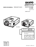


Multimedia Projector
SERVICE MANUAL
PRODUCT CODE
1 122 108 00
(MA8A)
1 122 109 00
(PA8A)
1 122 109 02
(PA8C)
1 122 110 00
(MB8A)
1 122 111 00
(PB8A)
1 122 111 02
(PB8C)
Original Version
REFERENCE NO.
SM
5110261
FILE NO.
Model No. PLC-XP45
PLC-XP40
U.S.A., Canada,
Europe, Asia, Africa
U.K
Chassis No. MA8-XP4500
MB8-XP4000
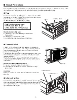
NOTE:
Match the Chassis No. on the unit’s
back cover with the Chassis No. in the
Service Manual.
If the Original Version Service
Manual Chassis No. does not match
the unit’s
, additional Service
Literature is required. You must refer to
“Notices” to the Original Service
Manual prior to servicing the unit.
PLC-XP45
PLC-XP40
Summary of Contents for PLC-XP40
Page 50: ... 50 CXA2101AQ RGB Matrix IC4101 IC Block Diagrams BH3540 Volume Control IC1652 ...
Page 54: ... 54 LB1645 Motor Drive IC1601 LC863316 SUB CPU IC1851 IC Block Diagrams ...
Page 55: ... 55 ML60851 USB I F IC9801 M62393 D A IC212 IC2381 IC Block Diagrams ...
Page 56: ... 56 M62399 D A IC3501 IC3551 IC Block Diagrams PW365 System Control Scan Converter IC301 ...
Page 57: ... 57 STR Z2156 Power Switching IC651 IC Block Diagrams SII161ACT DVI I F IC8001 ...
Page 58: ... 58 TA1287 RGB YUV Converter IC4551 TB1274AF Video Decoder IC1101 IC Block Diagrams ...
Page 59: ... 59 IC Block Diagrams TDA7056 Audio Output IC1631 IC1632 ...
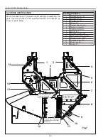
Page 88: ...MA8 XP4500 MB8 XP4000 Mechanical Parts List 88 51 a 51 42 42 51 b 21 a 21 b 21 ...
Page 92: ... MA8A Oct 2001 2000 Printed in Japan SANYO Electric Co Ltd ...


