background image

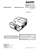
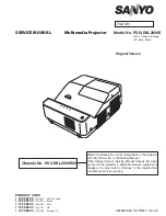
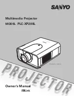
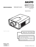
Multimedia Projector

SERVICE MANUAL

PRodUCt CodE 

1 122 396 40


(KL3AB)

1 122 397 40


(LL3AB)

1 122 397 42


(LL3CB)

original Version

REFERENCE NO. 

SM

5111160-00

 FILE NO.

Model No.  PLC-XE50A

U.S.A., Canada,


Europe, U.K. 

Asia, Africa

Chassis No.   KL3-XE50A00

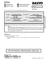
Match the Chassis No. on the rating label of the projector with 

the Chassis No. in the Service Manual.

 If  the  Original  Version  Service  Manual  Chassis  No.  does  not 

match the projector's, additional Service Literature is required. 

You must refer to “Notices” to the Original Service Manual prior 

to servicing.

Summary of Contents for PLC-XE50A

Page 1: ...PLC XE50A U S A Canada Europe U K Asia Africa Chassis No KL3 XE50A00 Match the Chassis No on the rating label of the projector with the Chassis No in the Service Manual If the Original Version Service Manual Chassis No does not match the projector s additional Service Literature is required You must refer to Notices to the Original Service Manual prior to servicing ...

Page 2: ...rator lens adjustment 36 Relay lens Out adjustment 37 Projection Lens focus adjustment 38 Electrical Adjustments 40 Service Adjustment Menu Operation 40 Circuit Adjustments 41 Test Points and Locations 46 Service Adjustment Data Table 48 Chassis Block Diagram 63 Chassis over view 63 System control 64 Lamp control 65 Audio circuit 66 Power supply protection circuit 67 Eco Standby mode Sub CPU 68 Fa...

Page 3: ...re replacing the cabinet cover thoroughly inspect the inside of the cabinet to see that no stray parts or tools have been left inside Before returning any projector to the customer the service personnel must be sure it is completely safe to operate without danger of electric shock Service Personnel Warning Eye damage may result from directly viewing the light produced by the Lamp used in this equi...

Page 4: ...al Analog RGB Mini D sub 15 pin Terminal x 1 Computer Input 2 Monitor Output Terminal Analog RGB Mini D sub 15 pin Terminal x 1 In Out switchable Audio Input Computer Jack Mini Jack stereo x 1 Service Port Connector Mini DIN 8 pin x 1 Audio Output Jack Mini Jack stereo x 1 Variable Audio Internal Audio Amp 2 0 W RMS Built in Speaker 1 speaker ø2 0 50 mm Power Voltage and Power Consumption AC 100 1...

Page 5: ...e main board Remove the cabinet top and main board Refer to Fig 2 Take the fuse off and replace the new one with the specified type This projector provides the following circuit protections to operate in safety If the abnormality occurs inside the projector it will automatically turn off by operating one of the following protection circuits Fuse Part No 323 025 1204 TYPE 8A 250V FUSE LITTLE FUSE I...

Page 6: ...ly When the inter nal temperature reaches near 100 C the thermal switch opens to stop the operation of the power supply circuit The thermal switch cannot be reset itself automatically even if the internal temperature becomes normal Reset the thermal switch following to the below procedure How to reset the thermal switch 1 Insert the sharp tool like a screwdriver into a hole on the cabi net from th...

Page 7: ...filter care and cleaning below Ventilation slots of the projector are blocked In such an event reposition the projector so that ventilation slots are not obstructed Check if projector is used at higher temperature place Normal operating temperature is 5 to 35 C or 41 to 95 F Warning temperature and power failure protection TheprojectorisshutdownandtheWARNINGTEMP indicator lights red When the proje...

Page 8: ...e noticed contact your authorized dealer or service station for proper cleaning Note When cleaning the air filter protect the infrared remote receiver with a soft cloth to avoid damaging it If the filter is heavily clogged and unable to clean replace it with a new one Consult your dealer for details Replacement Filter Part No 610 335 4057 Air filter Pull up the tab and remove Cleaning the Air Filt...

Page 9: ...plug the AC power cord before cleaning First remove the dust with a blower Then gently wipe the projection window surface Use a cleaning paper moistened with methyl alcohol methanol Avoid excessive use of cleaner Do not use abrasive cleaners solvents or other harsh chemical cleaners to avoid damaging the projection window Cleaning the Projection Window CAUTION This projector is equipped with a pro...

Page 10: ... disassemble and clean the optical unit Disassembly Cleaning Disassembly cleaning method should only be performed when the unit is considerable dirty and cannot be sufficient ly cleaned by air spraying alone Be sure to readjust the optical system after performing disassembly cleaning 1 Remove the cabinet top and main units following to Me chanical Disassemblies 2 Remove the optical base top follow...

Page 11: ...r can become very hot CAUTION Turn off the projector and unplug the AC power cord Let the projector cool for at least 45 minutes Loosen the two 2 screws that secure the lamp Lift the lamp out of the projector by using the handle 1 3 Replace the lamp with a new one and secure the two 2 screws Make sure that the lamp is set properly Close the lamp cover and secure the screw 4 Remove the screw from t...

Page 12: ... with the LAMP REPLACE indicator lighted may increase the risk of lamp explosion A Lamp may explode as a result of vibration shock or degradation as a result of hours of use as it comes to the end of life Risk of explosion may differ according to the environment or conditions in which the projector and lamp are being used IF A LAMP EXPLODES THE FOLLOWING SAFETY PRECAUTIONS SHOULD BE TAKEN If a lam...

Page 13: ...1 5 Teco used time in the Eco mode Tnormal used time in the Normal mode and Auto mode You can check the lamp used time following to the below procedure 1 Press and hold the ON STAND BY button on remote control unit for more than 20 seconds 2 The projector used time and lamp used time will be displayed on the screen briefly as follows Counter Projector 450 H Lamp Normal 200 H Eco 250 H Correspondin...

Page 14: ... factory and the Key lock function is disabled Please refer to the owner s manual for further information of the security functions Function Description Key lock Locks operation of the top control or the remote control If the Key lock is enabled with top control lock the projec tor can no longer be started Initial setting Key lock function is disabled PIN code lock Prevents the projector from bein...

Page 15: ...e original other wise it may cause lose of performance and product safety The wiring method of the leads and ferrite cores should be returned exactly the same state as the original otherwise it may cause lose of performance and product safety Screws Expression Type Diameter x Length mm T type M Type Tapping screw Machine screw 1 Remove the screw A M3x8 and remove the Lamp cover 2 Loosen the 2 scre...

Page 16: ... 2 Remove the screw B T3x8 remove the R C board R C pipe and remove the Decoration R C 3 Remove the Spacer Decoration Inray LED and Shield top B Cabinet Top ass y A A A A A A A A A Cabinet Top ass y Shield Top R C Board R C pipe Dec R C Spacer Dec Inray LED Cabinet Top Mechanical disassemblies ...

Page 17: ... 17 3 Main Board ass y removal 1 Remove the 3 screws A M2 5x6 screw B T3x8 screw C M4x6 and remove the Main board ass y C Main board ass y A A A B C B Mechanical disassemblies Hook Press this part ...

Page 18: ...ain board ass y D 2 Remove the 2 screws D M2 5x6 3 Remove the 3 screws E T3x6 and AV panel 4 Remove the 4 nuts F and Holder AV D F E E E F F F AV Panel Holder AV Main board AV board Mechanical disassemblies ...

Page 19: ...e exhaust Fan ass y FN903 FN904 upward 2 Remove the 2 screws A T3x8 remove the stopper exhaust Fan and remove the FN903 FN904 Exhaust Fan ass y Exhaust Fan ass y A A Mounting exhaust duct FN903 FN904 Stopper exhaust fan Mechanical disassemblies ...

Page 20: ...w A M3x8 and remove the Lamp connector 2 Remove the screw B M2 5x6 and shield plate 3 Remove the 2 screws C T3x8 remove the screw D T3x8 and remove the Power Supply ass y Lamp connector A B C C D Power supply ass y Shield plate Mechanical disassemblies ...

Page 21: ... 21 Power supply ass y Insulation sheet A Insulation sheet B Power board T3x6 M2 5x6 T3x6 T3x6 Ballast unit Holder Power supply ass y disassemble Mechanical disassemblies T3x6 Spacer sheet A ...

Page 22: ... 22 6 Optical unit removal 1 Remove the 5 screws A T3x8 and remove the Optical unit A Optical unit A A A A Mechanical disassemblies ...

Page 23: ... and remove the Line filter board ass y 2 Remove the Shield plate A Line filter board ass y M3x6 Line filter board ass y Shield plate A A M3x6 Holder InsulatIion sheet AC A InsulatIion sheet AC B InsulatIion sheet AC C Line filter board Mechanical disassemblies ...

Page 24: ...crews A T3x8 remove the Spacer sheet remove the Holder SW and remove the Thermal Switch SW902 2 Remove the screw B T3x8 and remove the Lamp cover switch SW901 A Spacer sheet A B Holder SW Thermal SW SW902 Lamp cover SW SW901 Mechanical disassemblies ...

Page 25: ...ove the screw B T3x8 and remove the Duct ass y 2 Remove the screw C T3x8 and remove the Duct top 3 Remove the Fans FN901 FN902 FN905 and Temp board A A A A A A B C Duct ass y Duct ass y Duct top FN901 TEMP board Duct bottom FN902 FN905 Mechanical disassemblies ...

Page 26: ... 26 10 Speaker unit removal 1 Remove the 2 screws A T3x12 and remove the speaker unit A A M3x4 Speaker unit M3x4 Speaker Damper Damper Holder Spacer Mechanical disassemblies ...

Page 27: ... 27 Optical disassemblies 1 Projection lens removal 1 Remove the 4 screws M4x12 remove the shield plate and remove the projection lens Optical unit Projection lens Shield plate ...

Page 28: ...screws A M2 5x8 and remove the LCD panel prism unit 2 Remove the 2 screws B M2 5x4 remove the screw C M3x10 and remove the LCD panel prism ass y A A A A LCD panel prism unit B B C LCD panel prism ass y Damper Damper Mounting prism Optical disassemblies ...

Page 29: ...placing the LCD panel should be replaced whole of the LCD panels and prism ass y at once After replacing LCD Panel Prism ass y please check the following points Check that there is no color shading at the top bottom left or right of the screen If there is try to remove the shading following to the chapter Optical Adjustment Check the white balance If it needs the adjustment adjust the white balanc...

Page 30: ...he Integrator Lens ass y 2 Remove the 2 screws B M2 5x5 remove the Relay Lens ass y Integrator lens ass y A Integrator lens IN Flat surface Hooks Relay lens OUT Spring A B B Relay lens ass y Integrator lens ass y Relay lens ass y Optical disassemblies INTEGRATOE LENS Print marker this side Bottom side ...

Page 31: ...lm sheet Hooks Polarized grass IN 4 Polarized grass ass y removal 1 Remove the screw A M2 5x5 and remove the Polarized grass ass y R G B A Polarized grass ass y A A Polarized grass ass y Optical disassemblies ...

Page 32: ... 32 5 Optical base top removal 1 Remove the Optical base top B 2 Remove the 2 screws T3x8 and remove the Optical base top A Optical base top A Optical base top B Hook Optical disassemblies ...

Page 33: ... Name L03 INTEGRATOR LENS OUT L04 CONDENSER LENS OUT NC L05 CONDENSER LENS G L06 CONDENSER LENS B L07 CONDENSER LENS R L08 RELAY LENS IN L11 MIRROR B L12 MIRROR R L13 PRISM PBS L17 DICHROIC MIRROR B L18 DICHROIC MIRROR G Print marker this side Bottom side INTEGRATOE LENS Optical Parts Location and Direction Print Marker this side Print Marker this side Print Marker this side ...

Page 34: ...adjustment G Contrast adjustment B Contrast adjustment Integrator lens adjustment Relay lens out adjustment Projection lens focus adjustment Electrical Adjustments Fan control adjustment Panel type check and setting Auto calibration adjustment PC Auto calibration adjustment Component Auto calibration adjustment Video Common center adjustment 50 white adjustment PC White balance adjustment PC 50 wh...

Page 35: ...s below remove the Cabinet Top following to the Mechanical Disassembly Adjustments require a 2 0mm hex wrench and a slot screwdriver When you adjust Integrator lens or Relay lens adjustment you need to disconnect FPC cables of LCD panels on the main board Optical adjustment requires a 2 0mm hex wrench and a slot screwdriver Note Do not disconnect connectors on the main board because the projector ...

Page 36: ...d adjust the slot B to make color uni formity in white by using a slot screwdriver 2 If the shading appears on the top or bottom of the screen as shown in Fig 2 2 loosen 2 screws C and insert a slot screwdriver into the slot D and adjust color uniformity in white by turning a slot screwdriver up or down 4Tighten screws A and C to fix the Integrator lens unit Note The relay lens adjustment must be ...

Page 37: ...djust the adjustment base of relay lens assy to make color uniformity in white If the shading appears on the left or right of the screen as shown in Fig 3 loosen 1 screw A and adjust the slot B to make color uniformity in white by using a slot screwdriver 4Tighten the screw A to fix the relay lens unit Relay lens Out adjustment Optical Adjustments ...

Page 38: ...figure by operating the focus lever Screen size 78 3 Input a cross pattern 4The position of the projector is matched so that the picture may be come a rectangle Do not become a trapezoid Projection lens focus adjustment Focus lever Focus ring hole 8 cm Good NG NG Projection lens Focus adjusted this area Optical Adjustments ...

Page 39: ...n is adjusted by using slot B Pre adjustment 3The screws A1 A2 are lightly tightened and temporary is fixed 4 Focus on the entire screen is adjusted 5Tighten the 4 screws A A1 A2 A3 A4 Caution Confirm focus after it tightens up the screws A2 A1 A3 A4 Slot B 1 5 2 3 4 Optical Adjustments ...

Page 40: ...emory IC Please note that the lamp replace counter will be reset when the memory IC is replaced Lamp replace counter cannot be set to the previous val ue Caution to memory IC replacement When memory IC is replaced with new one the CPU writes down the default data of the service adjustments to the re placed IC as the mentioned on the service adjustment ta ble As these data are not the same data as ...

Page 41: ...viceAdjustmentMenuOperation forenteringtheservicemode and adjusting the service data White 100 Black 100 Circuit Adjustments CAUTION The each circuit has been made by the fine adjustment at factory Do not attempt to adjust the following adjust ments except requiring the readjustments in servicing otherwise it may cause loss of performance and product safety 16 steps gray scale pattern WARNING USE ...

Page 42: ...r R Type of LCD panel 3 Panel Type Setting Select group no 290 item no 1 and change data val ue from 10 to 0 or 20 depending on your LCD Panel type When the data value reaches 0 or 20 it returns to 10 quick ly The gamma characteristics changes according to your selection 2 Panel Type Check and Setting 1 Enter the service mode 2 Receive the 16 step grey scale computer signal with Com puter1 RGB mod...

Page 43: ...ta value to adjust the pedestal level and black level to be the same level 5 Connect an oscilloscope to test point TP35R and chassis ground 6 Select item no 1 and change data value to adjust the pedestal level and black level to be the same level 7 Connect an oscilloscope to test point TP35B and chassis ground 8 Select item no 2 and change data value to adjust the pedestal level and black level to...

Page 44: ...ge data value to obtain the minimum flicker on the screen 6 Project only red light component to the screen 7 Select item no 0 and change data value to obtain the minimum flicker on the screen 8 Project only blue light component to the screen 9 Select item no 2 and change data value to obtain the minimum flicker on the screen 10 Select group no 100 item no 92 and change data value to 0 to reset the...

Page 45: ...e tool Adjust the gamma correction by using the proper computer and PROJECTOR SERVICE TOOL software supplied sepa rately 12 Gamma Correction adjustment Video 13 Read Write of LCD panel gamma data when Main Board replacing The gamma adjustment data of each LCD panel has been adjusted preciously to much each LCD panel characteristics at factory When you replace the Main Board you need to read out th...

Page 46: ... K6N K6P K6Q K6R IC5001 K8D IC5201 K8F K8H K35B K8K TP35B TP_DHS TP_VHS K35G K8S TP35G K8T K35R TP35R IC801 IC1802 K401A K401B K7301 K801 IC5301 TPFANA TPFANB TPFANC IC501 MAIN BOARD Test Points and Locations Optical Adjustments ...

Page 47: ... 0 63 120 PreCoast PC Video 480i 7 0 63 121 PostCoast PC Video 480i 13 0 63 122 PreCoast PC Video 575i 7 0 63 123 PostCoast PC Video 575i 13 0 63 124 PreCoast PC Video 480p 7 0 63 125 PostCoast PC Video 480p 13 0 63 126 PreCoast PC Video 575p 7 0 63 127 PostCoast PC Video 575p 13 0 63 128 PreCoast PC Video 720p 60Hz 7 0 63 129 PostCoast PC Video 720p 60Hz 13 0 63 130 PreCoast PC Video 720p 50Hz 7 ...

Page 48: ... To Ban Pass Gain 1 0 0 3 11 C2DBDIAGONALGAIN Comb 2D Band Pass Diagonal Gain 1 3 0 3 12 C2DNBCWBCLGAIN Comb 2D Narrow Band Comb Wide Band Comb 1 1 0 3 13 RLUMASETUP Enable 7 5IRE Setup Enable 0 0 1 Effective only NTSC Signal Group 40 General 0 IP Mode Sets for IP Off 1 0 1 0 IP Block not used 1 IP OFF used with IP Block 1 3 2 PullDown Mode 1 1 3 bit0 Global Motion bit1 Video Motion 2 Detect Film ...

Page 49: ...T23 4 1 5 1 Video Motion Sensitivity Film Detection Sensitivity VOFSTVT 4 1 5 2 Video Motion Threshold Low VOFTHRDA 120 0 32767 3 Video Motion Threshold High VOFTHRDB 180 0 32767 4 Global Motion Threshold GMDTHRD 124 0 1023 Read only 5 23Film Mode Threshold FILMTHRD23 100 0 32767 6 Global Motion Window Start X GMDSTARX 10 0 2047 Range of detective for Film mode 7 Global Motion Window Stop X GMDSTO...

Page 50: ...0 0 4095 13 B ReferH 4095 4095 0 4095 14 B ReferL 1200 1200 0 4095 15 DXOutR 212 0 1023 16 DXOutG 212 0 1023 17 DXOutB 212 0 1023 18 H_Change_Pos 24 0 256 19 SH_Base 1092 0 4095 20 NRG_Pos 39 0 128 21 NRG_Width 39 0 255 22 OSD_Pos 2 0 3 23 OSD_Ptn 0 0 7 24 GammaCtrl 3 0 3 25 REF_GatePos 1 0 1023 26 REF_GateDur 144 0 1023 27 R BasePos 6 0 15 28 G BasePos 6 0 15 29 B BasePos 6 0 15 30 RGB Adjust 0 0...

Page 51: ...t 0 0 2047 MIN MAX Cyclic Operation 95 FrontCTalkR Start 126 0 255 96 FrontCTalkR End 129 0 255 97 FrontCTalkG Cent 0 0 2047 MIN MAX Cyclic Operation 98 FrontCTalkG Start 126 0 255 99 FrontCTalkG End 129 0 255 100 FrontCTalkB Cent 0 0 2047 MIN MAX Cyclic Operation 101 FrontCTalkB Start 126 0 255 102 FrontCTalkB End 129 0 255 103 R DCOffset NGain 0 0 1023 MIN MAX Cyclic Operation 104 R DCOffset N1 ...

Page 52: ...G DCOffset P1 2036 0 2047 MIN MAX Cyclic Operation 157 G DCOffset P2 0 0 2047 MIN MAX Cyclic Operation 158 G DCOffset P3 0 0 2047 MIN MAX Cyclic Operation 159 G DCOffset P4 0 0 2047 MIN MAX Cyclic Operation 160 G DCOffset P5 0 0 2047 MIN MAX Cyclic Operation 161 G DCOffset P6 0 0 2047 MIN MAX Cyclic Operation 162 G DCOffset P7 0 0 2047 MIN MAX Cyclic Operation 163 G DCOffset P8 0 0 2047 MIN MAX Cy...

Page 53: ...47 215 PRE_COLSHD_SEL 0 0 255 216 HSYNC_FOLLOW 1 0 1 217 DELAY_HSYNC 30 0 2047 218 DELAY_VSYNC 16 0 255 219 VSYNC_FOLLOW 0 0 1 220 BLANK_RCENTER 0 0 2047 MIN MAX Cyclic Operation 221 BLANK_RSTART 128 0 255 222 BLANK_REND 128 0 255 223 BLANK_GCENTER 0 0 2047 MIN MAX Cyclic Operation 224 BLANK_GSTART 128 0 255 225 BLANK_GEND 128 0 255 226 BLANK_BCENTER 0 0 2047 MIN MAX Cyclic Operation 227 BLANK_BST...

Page 54: ...ting RC Mode 0 0 1 0 Normal RC Mode 1 Promethean RC Mpde 71 Force Model Option Model Option Force Setting 0 0 2 0 Normal 1 Force for XE50 2 Force for XL50 80 Panel life test mode Setting panel life test mode 1 0 1 0 Life test mode 1 Normal Group 201 Option signal 0 FrameLock Option 1 0 1 0 FrameLockOFF at PC signal 1 FrameLockON at PC signal and 47Hz Vfreq Panel frequency of input signal 1 AV TRUE...

Page 55: ...DIMMER_CTRL_LEVEL9 Luminance Level 9 Data for Dimmer Dim Level 9 at the less than the Value 63 0 255 9 DIMMER_CTRL_LEVEL10 Luminance Level 10 Data for Dimmer Dim Level 10 at the less than the Value 70 0 255 10 DIMMER_CTRL_LEVEL11 Luminance Level 11 Data for Dimmer Dim Level 11 at the less than the Value 77 0 255 11 DIMMER_CTRL_LEVEL12 Luminance Level 12 Data for Dimmer Dim Level 12 at the less tha...

Page 56: ...ng Det 100 100 100 100 100 100 100 100 0 100 Normal Celling Down Up HiLand Normal Celling Down Up 9 Temp C A Warning High Temp C A to judge the Temp Error at High Clogging Det 100 100 100 100 100 100 100 100 0 100 Normal Celling Down Up HiLand Normal Celling Down Up 10 Temp A Warning Normal Temp A to judge the Temp Error at Normal Room 42 32 42 32 42 32 42 32 30 100 Normal Celling Down Up HiLand N...

Page 57: ... 22 Normal Fan1 Min Fan voltage value at Normal unit 0 1V 60 100 60 100 60 100 60 100 0 255 Normal Celling Down Up HiLand Normal Celling Down Up 23 Normal Fan1 Max 85 100 85 100 85 100 85 100 0 255 Normal Celling Down Up HiLand Normal Celling Down Up 24 Normal Fan2 Min 70 110 70 110 70 110 70 110 0 255 Normal Celling Down Up HiLand Normal Celling Down Up 25 Normal Fan2 Max 110 110 110 110 110 110 ...

Page 58: ... 0 1000 3 GAIN AREA V START White Level Acquiring Area V Start Position 500 0 1000 4 Image AREA H WIDTH Black White Level Acquiring Area 13 0 4095 5 Image AREA V HIGHT Black White Level Acquiring Area Height 9 0 4095 6 OFFSET target Target Value of Black Level Adj 3 0 127 7 OFFSET torelance Torelance of Black Level Adj 1 1 127 8 GAIN target Target Value of White Level Adj 238 0 255 9 GAIN torelanc...

Page 59: ... 1 Disable 1 Frequency Step Frequency Steps of TotalDot 1 0 3 2 Frequency Threshold Total Dot Freqency Threshold 5 0 10 0 10 Not matched 3 Fine Phase Do Phase Adj after Total Dot Adj 1 0 1 0 Executes Fine Phase 1 Not Execute 4 BLKDET Black Level Detection Area 1 0 7 5 PHASEMSK Phase Detection Filter 0 0 3 0 Effective All Bit 1 Disable Lower 1 bit 2 Disable Lower 2 bit 3 Disable Lower 3 bit Group 2...

Page 60: ...3 YCbCr 575P 0 Total Dots Read only 864 0 4095 Read only 1 Disp Dots 680 0 4095 2 H Back Porch 143 0 4095 3 V Back Porch 55 0 4095 4 Disp Line 550 0 4095 Group 524 YCbCr 720P 60 0 Total Dots Read only 1650 0 4095 Read only 1 Disp Dots 1248 0 4095 2 H Back Porch 312 0 4095 3 V Back Porch 34 0 4095 4 Disp Line 700 0 4095 Group 525 YCbCr 720P 50 0 Total Dots Read only 1980 0 4095 Read only 1 Disp Dot...

Page 61: ...h 174 0 4095 3 V Back Porch 62 0 4095 4 Disp Line 540 0 4095 Group 544 RGB Video 720P 60 0 Total Dots 1650 0 4095 1 Disp Dots 1248 0 4095 2 H Back Porch 312 0 4095 3 V Back Porch 34 0 4095 4 Disp Line 702 0 4095 Group 545 RGB Video 720P 50 0 Total Dots 1980 0 4095 1 Disp Dots 1246 0 4095 2 H Back Porch 314 0 4095 3 V Back Porch 34 0 4095 4 Disp Line 702 0 4095 Group 546 RGB Video 1080i 60 0 Total ...

Page 62: ...4 0 4095 3 V Back Porch 46 0 4095 4 Disp Line 1070 0 4095 Group 560 HDCP 480P 7 Over Scan Over Scan Rate 0 25 5 at 0 1 steps 0 255 8 VSBEG 0 15 Group 561 HDCP 575P 7 Over Scan Over Scan Rate 0 25 5 at 0 1 steps 0 255 8 VSBEG 0 15 Group 562 HDCP 720P 60 7 Over Scan Over Scan Rate 0 25 5 at 0 1 steps 8 VSBEG 0 15 Group 563 HDCP 720P 50 7 Over Scan Over Scan Rate 0 25 5 at 0 1 steps 0 255 8 VSBEG 0 1...

Page 63: ...UDIO RGB DHS DVS DCLK 34 32 28 B 0 7 G 0 7 R 0 7 PW_DB 0 9 PW_DG 0 9 PW_DR 0 9 DB 0 9 PW_DG 0 9 PW_DR 0 9 A 1 23 22 20 11 13 26 288 206 204 82 260 258 78 172 256 262 264 18 17 16 28 29 135 331 161 21 10 14 17 12 2 10 1 10 12 PC1 PC2_SW 265 214 273 124 368 R C RC_MCU MCU_EX_UART EX_MCU_UART PW_EX_UART EX_PW_UART EX_CPU_UART CPU_EX_UART IRRCVR0 MCU_STAT POWER_SW_MCU 1 5 11 15 17 3 7 13 16 18 2 5 4 2...

Page 64: ...7 273 97 345 POWER_LED BLAST_AC BALAST_AC FAN_ERR LAMPREP_LED ON_3 3V ON_15 5V 346 413 269 345 344 CABLE_SW WARNING_LED ON_5VA 182 COMP_SW 187 184 DDC_SW2 1 DDC_SW1 101 110 P_FAIL P_FAIL FAN_SW1 FAN_SW1 LAMPDC_ON DC_ON READY_LED 215 P Fail L 285 89 92 91 CHO_TXD CHO_RXD CHO_TXD CHO_RXD MUTE 295 26 201 IRRCVR0 SCL0_5V SDA0_5V SCL0 SDA0 IRRCVR0 214 212 293 IC301 SCALER PW190 Q6844 Q6843 D6832 D6831 ...

Page 65: ...W901 LAMP COVER SW CHO_RXD LAMP_DET BALAST_AC LAMPDC_ON CHO_TXD IC9882 INVERTER 13 10 295 26 89 413 11 5 4 1 1 3 K8R K6R K8H K8S 1 2 POWER ON H POWER ON H POWER_SW_MCU L MCU H PW190 MAIN POWER LAMP COVER SW Power Control IC4891 IC4501 SUB CPU 12 Lamp control Chassis Block Diagrams ...

Page 66: ... 4 27 10 21 13 14 5 7 17 14 1 30 AUDIO OUT L R 9 22 3 5 2 6 Q5031 K50A K10A Q5032 Q5061 Q5063 Q5041 Q5042 Q5062 Q5064 IC5041 AUDIO OUT TDA7056 1 3 K8F IC301 SCALER SCL0_5V OUT_DET SDA0_5V SCL0_5V SDA0_5V 293 212 201 AUDIO MUTE MUTE Mute On H 21 22 17 18 23 24 25 Audio circuit Chassis Block Diagrams ...

Page 67: ...891 NAND ES6V ES16V ES 5V 1 2 5 6 9 IC8811 TEMP SENSOR3 MCO9801T LAMP PANEL OUTSIDE IC8821 TEMP SENSOR2 MCO9801T IC4831 TEMP SENSOR1 MCO9801T 26 2 13 295 P_FAIL P Fail L 215 345 344 ON_5VA 110 DC_ON LAMPDC_ON 92 89 413 212 293 SCL0_5V SDA0_5V IC9882 INVERTER SW901 12V 1 0V 16V IC5641 FAN_A D3621 D3621 D3617 D3611 11 IC7271 IC1411 S2 5V_PW IC1361 S3 3V_PW IC1351 S1 8V_PW IC5681 Q1371 IC1401 IC1371 ...

Page 68: ...OWER MAIN K8R POWER BOARD IC3801 LED K6R K8R S6V S16V S 5V ON_DC ES6V ES3 3V ES 5V S 5V ES16V ES 5V 5 9 6 2 1 Q683 Q3611 IC4595 IC4581 Q3641 Q3642 Q3695 Q3694 Q3692 16V S16V S6V POWER_SW_MCU POWER_SW_MCU POWER_SW_MCU IC301 Eco Standby Sub CPU Chassis Block Diagrams TABLE FOR PROJECTOR STATE AND CONTROLSIGNAL CONTROL SIGNAL STANDBY POWER POWER_SW_MCU LAMP_DC_ON ES6V S16V S6V S 5V ECO STANDBY STATE ...

Page 69: ...P SENSOR3 MCP9801T IC4831 TEMP SENSOR1 MCP9801T MAIN BOARD FAN_CON_B FAN_CON_A Power On H IC3531 D A M62334 IC4891 NAND 2 FAN_CON_C 3 1 2 4 1 6 7 215 285 212 293 SCL0 SDA0 SCL0_5V SDA0_5V IC1302 Power Error On P_Fail H SIGNAL MODE POWER ON STAND BY H L NORMAL ERROR H L FAN_SW1 P_FAIL P_FAIL Q3601 Power Error On P_Fail H FAN_ERR TPFANB K8S K8H K8T 413 3 1 4 4 BALAST_AC D3632 K6Q FN905 1 2 FAN_C 3 6...

Page 70: ...2 DDC SW Q6201 2 5 101 1 5 2 14 208 2 1 4 3 7 1 2 3 6 FAN CONTROL IC3501 DAC M62334 IC8811 TEMP SENSOR 3 MCP9801 K48E K8T TEMP MAIN 6 SCL SDA 211 294 5 IC1391 CONTROL MEMORY 2 1 IC8821 TEMP SENSOR 2 MCP9801 IC4831 TEMP SENSOR 1 LM76CH 4 3 IC6202 DDC SW 5 2 4 14 15 9 10 11 Q6211 9 11 DDC_SW2 IIC bus control circuit Chassis Block Diagrams ...

Page 71: ...ops blinking Q Q The projector is ready to be turned on with the ON STANDBY button Q Q The projector is operating normally Q Q The projector is in the Power management mode Q Q The temperature inside the projector is abnormally high The projec tor cannot be turned on When the projector is cooled down enough and the temperature returns to normal the POWER indicator emits a red light and the project...

Page 72: ...nal BALAST_AC to the lamp ballast board via IC4891 and SW901 lamp cover switch to stop operation of the lamp circuit An abnormality occurs on the secondary power supply Check power supplies 16V S6V S 5V S16V P_FAIL signal becomes Low when the abnormality occurs on any of the power supply lines An abnormality occurs on the fan control circuit Check FN901 FN902 FN903 FN904 FN905 and peripheral circu...

Page 73: ... with all of computer input sources Yes Yes Yes No No No Check following steps Check AV source selecting and decoding stage S Video source Check S video signal Y C S CHROMA signal is applied to pin 265 of IC301 Scaler and S Y signal is applied on pin 264 of IC301 S_SW signal S VIDEO L is input to pin 267 of IC301 Scaler Component video source Check component signal Y Cr Pr Cb Pb The component sign...

Page 74: ...connection of the terminal K8F Yes No Check following steps Check IC5041 9V_AUDIO and peripheral circuit Check the Mute signal at pin 7 of IC5041 The Mute signal is output from pin 201 of IC 301 Scaler The OUT_DET signal is sent from Audio Out terminal Mute On H at pin 201 of IC301 L at pin7 of IC5041 Check if the audio signal is observed at pins 5 and 7 of IC5041 Yes No Troubleshooting ...

Page 75: ...ock O 294 D21 SDA1 IIC Bus Control Data O 212 C22 SDA0 IIC Bus Control Data O 214 C24 IRRCVR0 Remote Control I 295 D22 CHO_TXS O 26 A26 CHO_RXD I 124 B25 PW_EX_UART O 368 E20 EX_PW_UART I 28 C26 KEY1 Key Control Input I 126 D25 KEY2 Key Control Input I 215 D24 P_FAIL Power Failure Signal Input Failure L I 30 E26 FAN_CON_B FAN Control_B O 127 E25 BATT alarm O 128 F25 FAN_CON_C FAN Control_C O 373 H...

Page 76: ..._EX LED Indicator O 290 L3 PW_LAMP_LED_EX LED Indicator O 94 H1 PW_FILTER_LED_EX LED Indicator O 92 K1 DC_ON_EX O 165 K2 LAMP_DET Lamp Detect i 187 H2 COMP_SW Component Detect O 419 G5 I O TC Alarm O 188 G2 I O CLK0 Alarm O 95 G1 INH Alarm O 96 F1 I O_RXD0 Alarm O 273 G3 MCU_STAT Eco Standby Mode I 189 F2 PW_MASTER_SDI Eco Standby Mode O 420 F5 PW_MASTER_SCK Eco Standby Mode O 97 E1 PW_MASTER_SD0 ...

Page 77: ... 77 IC Block Diagrams BA7078 Sync Separator IC5301 AN5870 Signal Switch IC5201 ...

Page 78: ... 78 FA5502 P F Control IC601 HIN202EIB RS 232C Driver IC3801 IC Block disgrams ...

Page 79: ... 79 L3E07110 LCD Driver Gamma Correction IC401 L3E06150 D A S H LCD Driver IC501 IC531 IC561 IC Block disgrams ...

Page 80: ... 80 L3E01060 Level Shift IC2501 IC2531 IC2561 M62334 DAC IC3501 IC Block disgrams ...

Page 81: ... 81 NJW1141 Audio Control IC5001 PW190 Scaler IC301 IC Block disgrams ...

Page 82: ...A SOLID Tantalum Oxide Solid Electrolytic AL SOLID Aluminium Solid Electrolytic ELECT Aluminum Foil Electrolytic NP ELECT Non polarised Electrolytic OS SOLID Aluminium Solid with Organic Semiconductive Electrolytic POS SOLID Polymerized Organic Semiconductive DL ELECT Double Layered Electrolytic PPS FILM Polyphenylene Sulfide Film MT PPS FILM Metalized Polyphenylene Sulfide Film MT PEN FILM Metali...

Page 83: ...E FILTER BOARD A1001 MAIN BOARD A2001 AV BOARD A2901 R C BOARD A6801 KEY SW BOARD A901 BALLAST UNIT A4831 TEMP BOARD FN904 Exhaust FN903 Exhaust LP900 Lamp Ass y FN901 Intake FN902 Intake FN905 Intake SW902 Thermal Switch SP901 Speaker Elecrical Parts Location A601 POWER BOARD ...

Page 84: ...224 8913 MT GLAZE 100K JA 1 16W R2056 301 224 8814 MT GLAZE 100 JA 1 16W R2057 301 225 1418 MT GLAZE 47K JA 1 16W R3001 301 224 8913 MT GLAZE 100K JA 1 16W R3003 301 224 8814 MT GLAZE 100 JA 1 16W R3011 301 224 8913 MT GLAZE 100K JA 1 16W R3013 301 224 8814 MT GLAZE 100 JA 1 16W R3021 301 224 8913 MT GLAZE 100K JA 1 16W R3022 301 224 8814 MT GLAZE 100 JA 1 16W R3031 301 224 8913 MT GLAZE 100K JA 1...

Page 85: ...L6 TB 305 015 8925 TR 2SC2812 L7 TB 305 163 1615 TR 2SC2812N L6 TB0 305 173 9816 TR 2SC3928A1R 305 173 9915 TR 2SC3928A1S Q2021 305 014 4512 TR 2SC2412K T146 R 305 014 4611 TR 2SC2412K T146 S 305 015 8727 TR 2SC2812 L6 TB 305 015 8925 TR 2SC2812 L7 TB 305 163 1615 TR 2SC2812N L6 TB0 305 173 9816 TR 2SC3928A1R 305 173 9915 TR 2SC3928A1S Q2071 305 014 4512 TR 2SC2412K T146 R 305 014 4611 TR 2SC2412K...

Page 86: ...S 305 015 8727 TR 2SC2812 L6 TB 305 015 8925 TR 2SC2812 L7 TB 305 163 1615 TR 2SC2812N L6 TB0 305 173 9816 TR 2SC3928A1R 305 173 9915 TR 2SC3928A1S Q5041 305 014 4512 TR 2SC2412K T146 R 305 014 4611 TR 2SC2412K T146 S 305 015 8727 TR 2SC2812 L6 TB 305 015 8925 TR 2SC2812 L7 TB 305 163 1615 TR 2SC2812N L6 TB0 305 173 9816 TR 2SC3928A1R 305 173 9915 TR 2SC3928A1S Q5042 305 014 4512 TR 2SC2412K T146 ...

Page 87: ...928A1S Q6841 305 014 4512 TR 2SC2412K T146 R 305 014 4611 TR 2SC2412K T146 S 305 015 8727 TR 2SC2812 L6 TB 305 015 8925 TR 2SC2812 L7 TB 305 163 1615 TR 2SC2812N L6 TB0 305 173 9816 TR 2SC3928A1R 305 173 9915 TR 2SC3928A1S Q6842 305 014 4512 TR 2SC2412K T146 R 305 014 4611 TR 2SC2412K T146 S 305 015 8727 TR 2SC2812 L6 TB 305 015 8925 TR 2SC2812 L7 TB 305 163 1615 TR 2SC2812N L6 TB0 305 173 9816 TR...

Page 88: ...ITOR C1041 303 438 0219 CERAMIC 0 1U K 16V 303 409 3426 CERAMIC 0 1U K 16V C1091 303 438 0219 CERAMIC 0 1U K 16V 303 409 3426 CERAMIC 0 1U K 16V C1300 303 438 0219 CERAMIC 0 1U K 16V 303 409 3426 CERAMIC 0 1U K 16V C1301 303 438 0219 CERAMIC 0 1U K 16V 303 409 3426 CERAMIC 0 1U K 16V C1331 303 305 8515 CERAMIC 15P J 50V C1332 303 305 8515 CERAMIC 15P J 50V C1351 403 455 1012 CERAMIC 1U K 10V 303 4...

Page 89: ...000 ZA 1 16W C2073 403 455 1012 CERAMIC 1U K 10V 303 433 1112 CERAMIC 1U K 10V C2076 403 455 1012 CERAMIC 1U K 10V 303 433 1112 CERAMIC 1U K 10V C2082 301 226 1516 MT GLAZE 0 000 ZA 1 16W C2091 403 455 1012 CERAMIC 1U K 10V 303 433 1112 CERAMIC 1U K 10V C2092 301 226 1516 MT GLAZE 0 000 ZA 1 16W C2093 303 438 0219 CERAMIC 0 1U K 16V 303 409 3426 CERAMIC 0 1U K 16V C2504 303 438 0219 CERAMIC 0 1U K...

Page 90: ...409 3426 CERAMIC 0 1U K 16V C342 303 438 0219 CERAMIC 0 1U K 16V 303 409 3426 CERAMIC 0 1U K 16V C343 303 438 0219 CERAMIC 0 1U K 16V 303 409 3426 CERAMIC 0 1U K 16V C344 303 438 0219 CERAMIC 0 1U K 16V 303 409 3426 CERAMIC 0 1U K 16V C346 303 438 0219 CERAMIC 0 1U K 16V 303 409 3426 CERAMIC 0 1U K 16V C347 303 438 0219 CERAMIC 0 1U K 16V 303 409 3426 CERAMIC 0 1U K 16V C348 303 438 0219 CERAMIC 0...

Page 91: ...IC 0 1U K 16V 303 409 3426 CERAMIC 0 1U K 16V C3801 303 439 8412 CERAMIC 2 2U M 6 3V C3802 303 439 8412 CERAMIC 2 2U M 6 3V C3803 303 439 8412 CERAMIC 2 2U M 6 3V C3804 303 439 8412 CERAMIC 2 2U M 6 3V C3806 403 455 1012 CERAMIC 1U K 10V 303 433 1112 CERAMIC 1U K 10V C381 303 438 0219 CERAMIC 0 1U K 16V 303 409 3426 CERAMIC 0 1U K 16V C382 303 442 0519 CERAMIC 0 068U K 16V C383 303 442 0519 CERAMI...

Page 92: ...303 409 3426 CERAMIC 0 1U K 16V C4503 303 392 1215 ELECT 47U M 6 3V C4504 303 305 8812 CERAMIC 47P J 50V C4506 303 166 9515 CERAMIC 0 022U K 16V C451 303 438 0219 CERAMIC 0 1U K 16V 303 409 3426 CERAMIC 0 1U K 16V C452 303 438 0219 CERAMIC 0 1U K 16V 303 409 3426 CERAMIC 0 1U K 16V C453 303 438 0219 CERAMIC 0 1U K 16V 303 409 3426 CERAMIC 0 1U K 16V C454 303 438 0219 CERAMIC 0 1U K 16V 303 409 342...

Page 93: ... 303 439 8412 CERAMIC 2 2U M 6 3V C5204 303 439 8412 CERAMIC 2 2U M 6 3V C5206 303 439 8412 CERAMIC 2 2U M 6 3V C5207 303 439 8412 CERAMIC 2 2U M 6 3V C5208 303 397 5713 ELECT 100U M 10V 303 387 5617 ELECT 100U M 10V C5209 303 438 0219 CERAMIC 0 1U K 16V 303 409 3426 CERAMIC 0 1U K 16V C5211 303 438 0219 CERAMIC 0 1U K 16V 303 409 3426 CERAMIC 0 1U K 16V C5212 303 438 0219 CERAMIC 0 1U K 16V 303 4...

Page 94: ...2 3313 CERAMIC 0 1U K 25V C5651 303 391 5115 ELECT 100U M 16V 303 427 8417 ELECT 100U M 16V 303 296 9515 ELECT 100U M 16V C5652 303 438 0219 CERAMIC 0 1U K 16V 303 409 3426 CERAMIC 0 1U K 16V C566 303 342 3313 CERAMIC 0 1U K 25V C567 303 342 3313 CERAMIC 0 1U K 25V C568 303 342 3313 CERAMIC 0 1U K 25V C569 303 342 3313 CERAMIC 0 1U K 25V C5701 303 367 0410 CERAMIC 0 1U K 50V C5702 303 398 5415 ELE...

Page 95: ... 5415 ELECT 47U M 25V 303 387 7314 ELECT 47U M 25V C7802 303 342 3313 CERAMIC 0 1U K 25V C7803 303 438 0219 CERAMIC 0 1U K 16V 303 409 3426 CERAMIC 0 1U K 16V C7804 303 391 5115 ELECT 100U M 16V 303 427 8417 ELECT 100U M 16V 303 296 9515 ELECT 100U M 16V C7805 303 420 4812 CERAMIC 10U K 10V C7806 303 438 0219 CERAMIC 0 1U K 16V 303 409 3426 CERAMIC 0 1U K 16V C7821 303 398 5415 ELECT 47U M 25V 303...

Page 96: ...R1382 301 299 4919 MT GLAZE 470 FA 1 16W R1383 301 226 1516 MT GLAZE 0 000 ZA 1 16W R1384 301 294 3115 MT GLAZE 1K FA 1 16W R1401 301 037 5017 MT GLAZE 0 000 ZA 1 10W R1402 301 224 9019 MT GLAZE 10K JA 1 16W R1404 301 301 8119 MT GLAZE 3 9K FA 1 16W R1406 301 294 2613 MT GLAZE 4 7K FA 1 16W R1407 301 301 8119 MT GLAZE 3 9K FA 1 16W R1411 301 037 5017 MT GLAZE 0 000 ZA 1 10W R1412 301 224 8814 MT G...

Page 97: ...AZE 0 000 ZA 1 16W R3531 301 224 8913 MT GLAZE 100K JA 1 16W R3532 301 226 1516 MT GLAZE 0 000 ZA 1 16W R3533 301 225 1418 MT GLAZE 47K JA 1 16W R3539 301 037 5017 MT GLAZE 0 000 ZA 1 10W R355 301 226 1516 MT GLAZE 0 000 ZA 1 16W R356 301 226 1516 MT GLAZE 0 000 ZA 1 16W R3561 301 224 8913 MT GLAZE 100K JA 1 16W R3562 301 226 1516 MT GLAZE 0 000 ZA 1 16W R3563 301 225 1418 MT GLAZE 47K JA 1 16W R3...

Page 98: ... 8K JA 1 16W R4546 301 225 0619 MT GLAZE 5 6K JA 1 16W R4547 301 224 9316 MT GLAZE 1K JA 1 16W R4548 301 224 9019 MT GLAZE 10K JA 1 16W R4549 301 224 9019 MT GLAZE 10K JA 1 16W R4550 301 224 9019 MT GLAZE 10K JA 1 16W R4555 301 224 9019 MT GLAZE 10K JA 1 16W R457 301 225 1814 MT GLAZE 47 JA 1 16W R4578 301 224 9316 MT GLAZE 1K JA 1 16W R4579 301 224 9019 MT GLAZE 10K JA 1 16W R4580 301 224 9019 MT...

Page 99: ... 5K FA 1 16W R5624 301 294 2613 MT GLAZE 4 7K FA 1 16W R563 301 224 9019 MT GLAZE 10K JA 1 16W R5641 301 224 9415 MT GLAZE 1M JA 1 16W R5642 301 225 0114 MT GLAZE 27K JA 1 16W R5643 301 224 8913 MT GLAZE 100K JA 1 16W R5644 301 237 2915 MT GLAZE 51 JA 1 16W R5647 301 224 9019 MT GLAZE 10K JA 1 16W R5649 301 286 4717 MT GLAZE 30K JA 1 16W R5651 301 286 4717 MT GLAZE 30K JA 1 16W R5652 301 299 4810 ...

Page 100: ...W R7316 301 224 9316 MT GLAZE 1K JA 1 16W R7317 301 224 9019 MT GLAZE 10K JA 1 16W R7318 301 226 1516 MT GLAZE 0 000 ZA 1 16W R7319 301 226 1516 MT GLAZE 0 000 ZA 1 16W R7321 301 226 1516 MT GLAZE 0 000 ZA 1 16W R7322 301 226 1516 MT GLAZE 0 000 ZA 1 16W R7323 301 226 1516 MT GLAZE 0 000 ZA 1 16W R7801 301 224 9019 MT GLAZE 10K JA 1 16W R7802 301 224 9316 MT GLAZE 1K JA 1 16W R7803 301 224 9316 MT...

Page 101: ... 945 036 3529 R NETWORK 0X4 1 32W 945 037 0817 R NETWORK 0X4 1 16W RB561 945 036 3529 R NETWORK 0X4 1 32W 945 037 0817 R NETWORK 0X4 1 16W RB562 945 036 3529 R NETWORK 0X4 1 32W 945 037 0817 R NETWORK 0X4 1 16W RB563 945 036 3529 R NETWORK 0X4 1 32W 945 037 0817 R NETWORK 0X4 1 16W RB7201 945 034 5051 R NETWORK 22X4 1 32W 945 037 0824 R NETWORK 22X4 1 16W RB7202 945 034 5051 R NETWORK 22X4 1 32W 9...

Page 102: ...8 307 163 0414 DIODE 1SS352 TPH3 D3629 307 163 0414 DIODE 1SS352 TPH3 D3631 307 163 0414 DIODE 1SS352 TPH3 D3632 307 163 0414 DIODE 1SS352 TPH3 D3633 307 163 0414 DIODE 1SS352 TPH3 D3634 307 163 0414 DIODE 1SS352 TPH3 D4011 307 210 5416 DIODE RB551V 30 TE 17 D4012 307 210 5416 DIODE RB551V 30 TE 17 D4812 307 223 1115 ZENER DIODE 02DZ6 2Y TPH3 307 209 1214 ZD UDZS TE 176 2B D4813 307 223 1115 ZENER...

Page 103: ... 303 215 2214 CERAMIC 0 01U K 50V C625 303 215 2214 CERAMIC 0 01U K 50V C626 303 396 9613 CERAMIC 1U K 25V C627 303 113 4112 CERAMIC 2200P K 50V C629 303 265 3216 CERAMIC 1000P J 50V C631 303 157 4215 CERAMIC 220P J 50V C632 303 245 4417 CERAMIC 470P K 2K C633 303 265 3216 CERAMIC 1000P J 50V C634 303 113 4112 CERAMIC 2200P K 50V C641 303 367 0410 CERAMIC 0 1U K 50V C644 303 417 9912 CERAMIC 4 7U ...

Page 104: ...4 DIODE 1SS352 TPH3 307 149 0810 DIODE 1SS355 TE 17 D631 307 163 0414 DIODE 1SS352 TPH3 307 149 0810 DIODE 1SS355 TE 17 D632 307 247 8827 DIODE RF101L2S D633 307 146 8116 DIODE EG01C D651 307 247 8827 DIODE RF101L2S D661 407 261 9504 DIODE YG862C10R D662 307 202 9801 DIODE FMB 26L 307 253 7504 DIODE RB085T 60 D663 307 247 8827 DIODE RF101L2S D664 307 210 5416 DIODE RB551V 30 TE 17 D665 307 219 080...

Page 105: ... 105 C01 S3 S3 S3 S3 S3 S3 S3 S3 S3 C06 C07 C13 M61 M62 M52 M58 M63 M59 M55 M57 M56 M64 M65 M60 M69 M69 C02 C04 C10 S3 S1 C08 S2 S2 S2 C11 C12 C09 Mechanical Parts Location M70 Cabinet Parts ...

Page 106: ... 106 Red L02 R Green L02 G Blue L02 B Polarized Grass S6 S6 S6 M51 M51 M51 M51 C03 L10 L01 M68 M67 M66 L10 1 S8 S7 S7 Optical Parts MecanicalParts Location ...

Page 107: ... 107 MecanicalParts Location Integrator Lens In L09 L14 Relay Lens Out S6 S6 S6 S6 ...

Page 108: ... 108 L03 L13 L04 L11 L17 L18 L08 L12 L12 L07 L05 L06 In the Optical Unit MecanicalParts Location ...

Page 109: ...0 SCR S TPG PAN 3X6 S03 411 189 8600 SCR BIN 3X8 S06 411 189 6507 BOLT HEX SCT SW W 2 5X5 S07 312 069 7105 SPECIAL SCREW V S08 412 077 5701 SPECIAL SCREW 3 0X10V OPTICAL PARTS L01 610 346 4237 ASSY PNL PSM KM3AA L02 R 645 089 3476 POLARIZED GLASS IN R L02 G 645 101 1909 POLARIZED GLASS IN G L02 B 645 101 1916 POLARIZED GLASS IN B L03 645 098 8820 LENS INTEGRATOR OUT NC L04 645 095 9851 LENS CONDEN...

Page 110: ...SM5111160 00 PLC XE50A Dec 2009 DC 200 Printed in Japan SANYO Electric Co Ltd ...

Page 111: ...e manual original for chassis No KL3 XE50A00 models PLC XE50A File with the service manual No SM5111160 00 Note All the information of part numbers and values indicated on these diagrams are at the beginning of production To improve the performance there may be some differences to the actual set When you order the service parts use service parts code mentioned on the parts list in this service man...

Page 112: ...rial E Electrolytic P Electrolytic non polarized C Ceramic temperature compensation K Ceramic F Polyester N Polypropylene M Metalized polypropylene H Metalized polypromylar B Ceramic semiconductor G Metalized polyestel Y Composite film S Styrol T Tantalum oxide solid electrolytic U Organic semiconductive electrolyte D Electric double layer electrolytic Mark Tolerance A not specified B 0 1 C 0 25 D...

Page 113: ...00 Pin description of diode transistor and IC OEFY OEFY OEFY 065 OEFY OEFY OEFY OEFY OEFY OEFY 3 4 5 7EE 4 4 BUIPEF OPEF PMMFDUPS BTF NJUUFS SBJO BUF 4 4PVSDF L JPEF L 5SBOTJTUPS 5 L OEFY Diode Transistor FET IC FET ...

Page 114: ...mponents or the circuit board may easily occur Because of this you should use a soldering iron and solder that satisfy the following conditions when carrying out repair work Also soldering work must be done in a short time Soldering iron Use a soldering iron which is 70 W or equivalent and which lets you adjust the tip temperature up to 450 C 842 F It should also have as good temperature recovery ...

Page 115: ... FB VIN VCC IC621VCC CEXAVB 01100 C615 CEXAVB 01200 1 2 GND2 SCL0_5V TEMP SENSOR 1 OUTSIDE SDA0_5V CJ33CM C4831 K48E_4 16KK0 1 MN C4833 1 16GJ 10KA R4833 K48E_3 16KK10BB C4834 J10EG 045G K48E 1 4 K48E_1 CJ33CM C4832 1 16GJ10A R4832 K48E_2 S5V 1 16GZ0A R4835 1 16GJ10A R4831 MCP9801T M SN IC4831 1 SDA 2 SCL 3 ALART 4 GND 5 A2 6 A1 7 A0 8 VDD MICRO SW J10ES036G K690 1 1 2 3 3 K690_3 K690_1 COM NO NC ...

Page 116: ...R2008 Q5281 RN1111P 1 16GJ470A R2004 16KK0 1MN C5341 1 16GJ1KA R5337 16KK 0 1MN C6201 16KK0 11B 1 16GJ470A R2014 OUT_DET GSYNC X R5344 OUT_R 1 16GZ0A R5237 1 16GJ75A R2079 10KK1MN C2091 10KK11B K10A_2 1 16GJ4 7KA R6211 5VPC_A 16KK 0 1MN C6212 16KK0 11B 6 3KM2 2MN C3803 1SS352G D2071 X R2086 S5V 10KK1MN C2076 10KK11B G1 1 16GJ56KA R2023 1 16GJ75A R2094 1 16GJ10A R2041 5VPCDDC_B 10KK2 2GQ C4003 ES5V...

Page 117: ...K0 1MN C331 16KK0 11B 16KK0 1MN C322 16KK0 11B CR VIDEO ON_15 5V SCLK_PW_EXT RSQ025P03G Q1371 1 2 3 4 5 6 ES3 3V IC801 S29GL064N90TFI 41 DQ13 42 DQ6 43 DQ14 44 DQ7 45 DQ15 A 1 46 VSS 47 BYTE 48 A16 1 A15 2 A14 3 A13 4 A12 5 A11 6 A10 7 A9 8 A8 9 A19 10 A20 11 WE 12 RESET 13 A21 14 WP ACC 15 RY BY 16 A18 17 A17 18 A7 19 A6 20 A5 21 A4 22 A3 23 A2 24 A1 25 A0 26 CE 27 VSS 28 OE 29 DQ0 30 DQ8 31 DQ1 ...

Page 118: ... C9 GIN8 152 C10 GIN10 153 C11 RIN8 154 C12 RIN10 155 C13 TEST5 156 C14 TEST4 157 C15 TEST3 158 C16 TEST2 159 C17 TEST1 160 C18 GND 161 D18 TEST8 162 E18 TEST7 163 F18 ENBX4B 164 G18 STSQOB 165 H18 STSQEB 166 J18 MSELB 167 K18 DEB 168 L18 B1OUT8 169 M18 B1OUT10 170 N18 B1OUT11 171 P18 B2OUT8 172 R18 B2OUT9 173 T18 B2OUT10 174 U18 B2OUT11 175 V18 GND 176 V17 DYOUT 177 V16 DIRY 178 V15 NRG 179 V14 S...

Page 119: ...2 25EM103T C2574 K35B35 SDATA R_MON DG_1 0 9 X C554 G_ENBY 1 2 DR_DX 25KK1GQ C3569 1 16GJ100A R2562 K35B05 15 5V_PNL CJ22CM C1527 1 16GZ0A R552 16KK0 1MN C545 16KK0 11B R_DX K35B08 DG_ENBY2 R_DY R1JA0R04G RB563 R1EB0R04G 1 16GJ100A R2533 R_CLX 1 16GZ0A R3562 L26B3470G L2521 16KK0 1MN C3561 16KK0 11B CJ22CM C1542 L26B3470G L2581 CJ22CM C1577 K35G02 R_CLXB 1 16GZ0A R556 X C2502 15 5V_PNL 16KK0 1MN C...

Page 120: ...1 1 16GJ10KA R3623 16KK0 1MN C3624 16KK0 11B 25EM 473T C7841 1 16GF 6 8KA R7847 SP L3CZ220PG L4813 OUT_R L26B 3470G L3636 ES5V 16KK0 1MN C4583 16KK0 11B 10KK1MN C4591 10KK11B 6 3KK10BA C4582 6 3KK10MB TA48S00AFP IC4581 1 EN 2 IN 3 GND 4 OUT 5 ADJ 6 GND 16KK0 1MN C4593 16KK0 11B 1 16GF3 9KA R4597 1 10GZ0 0 R4592 1 10GZ0C L4591 X C4586 ES5V ES3 3V 1 10GZ0C L4581 6 3KK10BA C4592 6 3KK10MB 1 10GZ0 0 R...

Page 121: ...nted Wiring Board Diagrams This projector is isolated from AC line by using the internal converter transformer Please pay attention to the following notes in servicing 1 Do not touch the part on hot side primary circuit or both parts on hot and cold sides secondary circuit at the same time 2 Do not shorten the circuit between hot and cold sides 3 The grounding lead must be connected to the ground ...

Page 122: ...32 R326 R327 R328 C1811 R329 R1401 C1812 R1402 C1813 C1814 R521 C4501 R522 C1816 R523 C1817 R6803 R524 C1818 R5289 C1819 R8746 R526 R1022 R8747 R527 R8748 R8749 R337 R338 R1411 C1821 R339 D8751 C1822 R1412 R1413 C1823 R1414 C1824 Q1051 C301 D1801 L3621 R1416 C302 R8752 L3622 C303 R6813 L3623 R8754 R340 C304 L3624 L581 R341 C7201 C1829 IC1411 R8755 R8756 C7202 R342 C306 L3626 R8757 C307 C7203 R343 ...

Page 123: ... RB532 D8702 RB533 C5653 R8700 D8708 C6211 C891 D8709 C6212 C6213 Q6211 R2561 R2562 R3503 R2563 SC2071 D8711 C3530 1 12 25 36 24 13 48 37 IC2561 R5061 8 5 4 1 IC3501 L4581 R5062 C3533 R5063 C3534 R5064 L5331 C1401 C3536 R5066 R5642 C1402 R5067 C3538 R5068 D6201 Q5281 R3511 D6202 Q5282 R3512 Q5283 R3513 R3514 R5648 SC2081 L2071 R6201 R3515 R5649 R6202 R6203 Q5288 R6204 R5071 L4591 R6206 1 4 5 8 IC6...

Page 124: ...611 C672 C673 D662 D665 F631 Q611 Q612 L611 L612 DB611 C615 IC631 1 12 7 6 T651 D661 L613 L614 C613 C614 C661 R614 R685 1 2 K6C Q611H DB611H Q643 L631 1 12 K6R D633 D666 C674 Q661 R611 R612 R613 R615 R616 L663 R617 R619 R620 R621 R622 R623 R624 R625 R626 R627 R628 R629 R631 R633 R634 R636 R637 R638 R641 R642 R643 R644 R646 R648 R651 R652 C621 C622 C623 C625 R662 C626 C627 C629 C631 C633 C634 R671 ...

Reviews: