background image

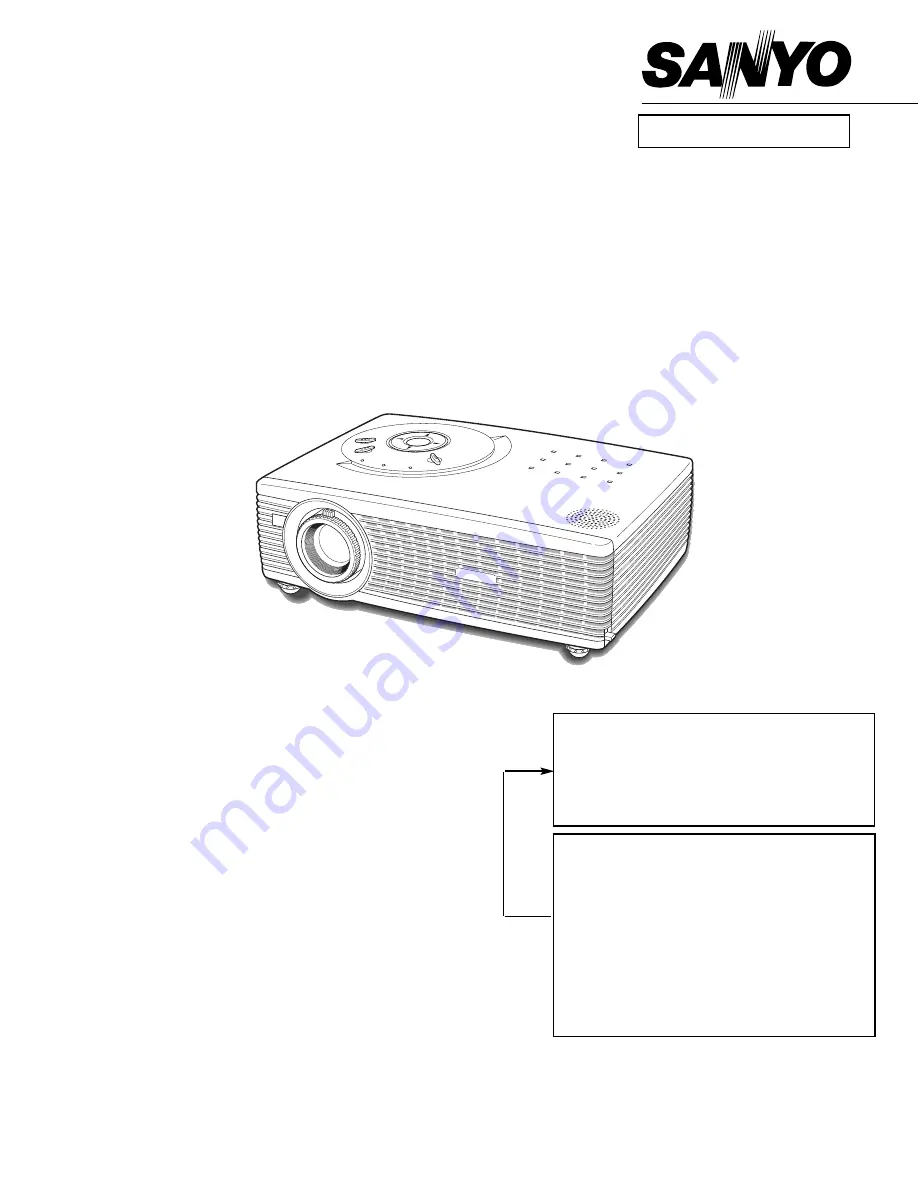
Multimedia Projector

SERVICE MANUAL  

PRODUCT CODE 
1 122 223 00

(MP3A)

1 122 226 00

(PP3A)

1 122 226 02

(PP3C)

Original Version

FILE NO.

Model No. PLC-SW30

U.S.A., Canada,

Europe, Asia, Africa

Chassis No. MP3-SW3000

NOTE:

Match the Chassis No. on the unit’s

back cover with the Chassis No. in the
Service Manual.

If the Original Version Service
Manual Chassis No. does not match
the unit’s

, additional Service

Literature is required. You must refer to
“Notices” to the Original Service
Manual prior to servicing the unit.

Summary of Contents for plc sw30 - SVGA LCD Projector

Page 1: ... S A Canada Europe Asia Africa Chassis No MP3 SW3000 NOTE Match the Chassis No on the unit s back cover with the Chassis No in the Service Manual If the Original Version Service Manual Chassis No does not match the unit s additional Service Literature is required You must refer to Notices to the Original Service Manual prior to servicing the unit ...

Page 2: ...Service adjustment data table______________________________ 26 29 Test points and locations ____________________________________ 30 Circuit block diagrams ________________________________________ 31 33 Power supply lines ______________________________________________ 34 Troubleshooting ______________________________________________ 35 38 Indicators and Projector Condition _________________________...

Page 3: ...re replacing the cabinet cover thoroughly inspect the inside of the cabinet to see that no stray parts or tools have been left inside Before returning any projector to the customer the service personnel must be sure it is completely safe to operate without danger of electric shock SERVICE PERSONNEL WARNING Eye damage may result from directly viewing the light produced by the Lamp used in this equi...

Page 4: ...Projection Lens F 1 6 1 8 lens with f 18 3 mm 21 9 mm with manual zoom and focus Throw Distance 4 3 21 2 1 3 m 6 5 m Projection Lamp 160 W Video Input Jack RCA Type x 1 Video and and Mini DIN 4 pin x 1 S Video AV Audio Input Jack Mini Jack stereo x 1 Computer Input Terminal VGA HDB 15 Terminal x 1 Computer Audio Input Jack Mini Jack stereo x 1 Control Port Connector Mini DIN 8 pin x 1 USB Connecto...

Page 5: ...tch 1 Remove the cabinet top following to Mechanical Disassemblies 2 Press the reset button on the thermal switch with a sharp pointed tool CAUTION Before press the reset button make sure that the AC cord must be disconnected from the AC outlet Circuit Protections This projector provides the following circuit protections to operate in safety If the abnormality occurs inside the pro jector it will ...

Page 6: ...rror Should the air filters become clogged with dust particles it will reduce the cooling fan s effectiveness and may result in internal heat build up and adversely affect the life of the projector To clean up the air filters follow the cleaning procedure below 1 Turn the projector off and disconnect the AC power cord from the AC outlet 2 Turn the projector upside down and remove the air fil ters ...

Page 7: ...p counter reset and then press the SELECT button The message Lamp replace counter reset is displayed Move the pointer to Yes and then press the SELECT button 3 Another confirmation dialog box appears and select Yes to reset Lamp Replace Counter Please refer to the owners manual for further informa tion Recommendation Should the air filter become clogged with dust particles it will reduce the cooli...

Page 8: ...le should be made following procedures in numerical order Following steps show the basic procedures therefore unnecessary step may be ignored Caution The parts and screws should be placed exactly the same position as the original otherwise it may cause loss of performance and product safety Fig 1 Cabinet Top removal 1 Screws Expression Type Diameter x Length mm T type M Type A A A B A Air filter P...

Page 9: ...oard upward Fig 3 Main Board removal 3 Main Board 1 Remove 2 screws A M3x6 and 2 screws B M3x6 black to take the Cabinet Front off 2 Remove 1 screw C T3x6 to the R C Board on the Cabinet Front Fig 2 Cabinet Front and R C Board removal 2 C A A B B R C Board Cabinet Front ...

Page 10: ...emoval 5 Thermal SW Lamp Cover Spacer Fig 4 1 Remove 1 screw A M4x4 and take the Rear Panel ass y upward off 2 Remove 2 screws B T3x8 to take the fan FN903 off 3 Remove 4 screws C T3x6 and take AV Board from the Rear Panel ass y off Rear Panel AV Board and FN903 removal 4 A B C B C C C AV Board Rear Panel FN903 Thermal SW Cover ...

Page 11: ...by pulling it 5 Remove 3 screws E T3x6 to take the Power Unit off Notes You can remove the connectors on the Power Unit after the Lamp Ballast Unit removal Fig 7 Power Unit Speaker and FN906 removal 7 A A A A B E E E D C Spacer Sheet Speaker Holder Speaker SP901 Power Board FN906 Holder Fig 6 1 Remove 2 screws A M3x8 and take the Lamp Cable off 2 Remove 6 screws B T3x10 and take the Optical Unit u...

Page 12: ... Ass y FN904 Fig 8 1 Remove 1 screw A M4x4 to take the Earth cable off 2 Remove 2 screws B T3x8 to take the Lamp Ballast Unit and the Filter Board off 3 Remove 2 screws C T3x6 to take the Lamp Ballast Unit off 4 Remove 3 screws D T3x6 to take the Filter Board off Lamp Ballast Unit and Filter Board removal 8 A B B C C D D D Lamp ballast Board Holder Filter Board Spacer Sheet Spacer Sheet Shield Pla...

Page 13: ... Cover SW removal 11 FN901 SW Board Spring Earth Plate Duct B B C C 1 Remove 1 screw A T3x8 to take the Duct under the Panel 2 Remove 1 screw B T3x8 to take the Holder with the Fans FN902 and FN905 off 3 Remove 2 screws C T3x10 to take the Fans FN902 and FN905 off 4 Remove 1 screw D T3x6 to take the Sensor Board off Fig 10 FN902 FN905 and Sensor Board removal 10 A B C C D Sensor Board FN902 FN905 ...

Page 14: ...Unit following to the Mechanical Disassemblies Fig 2 14 Fig 1 1 Remove 4 screws to take the Lamp Holder off Lamp Holder removal 1 1 Remove 3 screws to take the Projection Lens ass y off Projection Lens Ass y removal 2 Optical Unit Box Lamp Holder Optical Unit Box Projection Lens and Panel Prism Ass y ...

Page 15: ...zed Glass In removal 3 1 Remove 6 screws to take the Optical unit top off Optical Unit Top removal 4 Optical Unit Box Optical Unit Base Polarized glass_Red Polarized glass _Green and Blue Polarized glass sticked on Condenser lens R Polarized glass with mounting holder Fig 3 2 R B G Screw Polarized glass_Red Polarized glass_Blue Polarized glass_Green Screw Screw Optical Parts Disassemblies ...

Page 16: ...shown in figure below 14 12 Fig 5 3 1 2 4 9 Locations and Directions 13 6 1 Integrator lens IN 2 Mirror W 3 Integrator lens OUT 4 PBS polarizing beam splitter 5 Condenser lens IN 6 Dichroic mirror B 7 Dichroic mirror G 8 Relay lens IN 9 Mirror R 10 Relay lens OUT 11 Condenser lens R 12 Condenser lens G 13 Condenser lens B 14 Mirror B Key No Description 10 11 5 7 8 9 ...

Page 17: ...n Centre Adjustment following to chapter Electrical Adjustment Check the white uniformity on the screen If you find the color shading please adjust the white uniformity by using the proper computer and Color Shading Correction software supplied separately The software can be ordered as follows COLOR SHADING CORRECTION Ver 3 0 Service Parts No 645 056 6288 1 Remove 4 screws to take the Projection L...

Page 18: ...destal adjustment PC gain adjustment Video gain adjustment 480p pedestal adjustment 480p gain adjustment 480i gain adjustment Gamma adjustment PC and AV Common center adjustment White balance adjustment PC and AV Disassembly Replaced Parts LCD Prism Ass y Optical Unit Polarized glass R G B Optical Adjustments Electrical Adjustments Power Board Main Board Note The polarized glass R is sticked on th...

Page 19: ... K48L K66A K66B K66C K66D K66E and K66F on the main board because the projector can not turn on due to operate the power failure protection Fig 1 1 Polarized glass mounting base A Before Adjustment Input a 100 of black raster signal R G B CONTRAST ADJUSTMENT 1 Loosen a screw A Fig 1 1 1 2 on the polarized glass mounting base which you intend to adjust 2 Turn the polarized glass mounting base as sh...

Page 20: ... make color uniformity in green by using a slot screwdriver 2 If the shading appears on the top or bottom of the screen as shown in Fig 2 2 loosen 2 screws C with the 2 0mm hex driv er and adjust the slot D to make color uniformity in green by using a slot screwdriver 3 Tighten screws A and C to fix the Condenser lens unit Note The relay lens adjustment must be carried out after completing this ad...

Page 21: ...lot B to make color uniformity in white by using a slot screwdriver 2 If the cyan bar appears on the top or bottom of the screen as shown in Fig 4 2 loosen 2 screws C with the 2 0mm hex driver and adjust the slot D to make color uniformity in white by using a slot screwdriver 3 Tighten the screws A and C to fix the relay lens unit Fig 4 1 A Slot B b a a Moving of slot B b White Fig 4 2 Slot D Movi...

Page 22: ...djustments following to the Electrical Adjustments The data of lamp replacement monitor timer is stored in the IC1841 Please note that the lamp replace counter is reset when the memory IC IC1841 is replaced Lamp replace counter can not be set to the previous value Caution to memory IC replacement When IC1841 is replaced with new one the CPU writes down the default data of the service adjustments t...

Page 23: ...hite 50 pat tern Composite video signal Computer signal 0 7Vp p 75Ω terminated 16 steps gray scale pattern SVGA Component Video signal 0 7Vp p 75Ω terminated 16 steps gray scale white 100 and black 0 pat tern 480i format and 480p format Picture control mode STANDARD mode unless otherwise noted Note Please refer to Service Adjustment Menu Operation for entering to the service mode and adjusting the...

Page 24: ...ite Level 1 Receive the 16 step gray scale composite video sig nal with Video Video mode 2 Enter the service mode 3 Connect an oscilloscope to test point TPR1 and chassis ground 4 Select item no 7 and change data value to adjust waveform a to be minimum amplitude 5 Connect an oscilloscope to test point TPG1 and chassis ground 6 Select item no 8 and change data value to adjust waveform a to be mini...

Page 25: ...Video Video mode 2 Enter the service mode 3 Measure luminance on the screen with the luminance meter It is B for the reading of luminance meter 4 Change the signal source to the 50 whole white computer signal with Video Video mode 5 Select item no 16 and change data value to make the reading of luminance meter to be B x 22 m Gamma adjustment Electrical Adjustments PC WHITE BALANCE ADJUSTMENT 1 Rec...

Page 26: ...e same as NTSC 35 SubColor 480i 575i VPC3230 N A Note 2 N A 29 29 575i the same as PAL 36 0 37 V Line Color Shading Correction Setting R1 L3E7070K0A 2 Vertical Line Color Shading Correction 38 V Line Color Shading Correction Setting R2 L3E7070K0A 1 39 V Line Color Shading Correction Setting R3 L3E7070K0A 254 40 V Line Color Shading Correction Setting G1 L3E7070K0A 2 41 V Line Color Shading Correct...

Page 27: ...A 7 7 95 AFC other1 VPC3230 N A Note 1 N A 540 540 96 AFC other2 VPC3230 N A Note 1 N A 536 536 97 Horizontal Peaking Filter VPC3230 N A Note 1 N A 1 1 98 Peaking Gain VPC3230 N A Note 1 N A 2 2 99 Peaking Filter Coring Enable VPC3230 N A Note 1 N A 0 0 101 Horizontal Lowpass Filter VPC3230 N A Note 1 N A 1 1 102 Horizontal Lowpass Filter Chroma VPC3230 N A Note 1 N A 0 0 103 DOR VPC3230 N A Note ...

Page 28: ...331 Position Horizontal 1080i PIXEL 508 N A 517 N A 332 Position Vertical 1080i PIXEL 382 N A 383 N A 333 Expand Ratio Vertical 60Hz PIXEL 7 N A For RGB NTSC 480i 334 Expand Ratio Horizontal 60Hz PIXEL 36 N A 335 Position Horizontal 60Hz PIXEL 517 N A 336 Position Vertical 60Hz PIXEL 383 N A 337 Expand Ratio Vertical 50Hz PIXEL 20 N A For RGB PAL 575i 338 Expand Ratio Horizontal 50Hz PIXEL 40 N A ...

Page 29: ...io Horizontal 50Hz PIXEL 30 N A 375 Position Horizontal 50Hz PIXEL 512 N A 376 Position Vertical 50Hz PIXEL 385 N A 400 Gamma Shift Combination ON OFF 1 0 each source separate 1 PC source only separate 401 PC Frame Lock OFF 0 0 ON for all source 1 OFF at PC 402 Auto Grayscale black control start point 31 403 Auto Grayscale black control limit point 16 404 Auto Grayscale black control target point ...

Page 30: ...TPVVS IC101 K8W TE301 K8V K8G 1AA4B10C3650A K8A IC301 K25G K8F K25B TPRESET TPG1 TPDVS K25R TPDHS K8E IC3561 IC3551 TPB1 IC3571 IC501 K66A K66B IC401 IC531 TEGND2 K8H IC561 TPR1 TP2561 IC9401 IC3501 TP2531 TPVHS IC8201 TPG1 TPB1 TPR1 Electrical Adjustments MAIN BOARD Test Points and Locations ...

Page 31: ...C RESET SW RGB SCART Y Cb Cr 480i 575i RGB Y Cb Cr L R L R RGB H V Video Y C Audio RGB Component B G R IC5301 RGB_SYNC IC5302 YUV_SYNC IC1881 INVERTER IC1882 SUB CPU FAN CONTROL FANS LED POWER FAIL SYSTEM BUS IIC BUS SYSTEM BUS VIDEO RGB YUV IC5201 RGB SELECTOR IC301 MAIN CPU OSD De INTERLACE IC401 COLOR CORRECTION IC501 B PANEL DRIVER IC531 G PANEL DRIVER IC561 R PANEL DRIVER D SUB_15 UNIT_LAMP B...

Page 32: ...VY VUV G_SYNC G_SYNC 480p 575p only Other sources H V H RGB SCART YUV 480i 575i RGB YUV VIDEO Y C GREF GCOAST GCLK GFBK CLAMP GVS IIC_2 IIC_1 VHS VVS VPEN VFIELD VCLK VHDREN IC5303 PC AV_SW S_SW FILT_480p 575p GVS GHS DR DG DB ROUT GOUT BOUT RO DHS DVS DCLK TPR1 SCLK SDATA IC3561 DAC M62398 IC3571 DAC M62398 IC3551 DAC M62393 IC1881 BUFFER 74LCX541 BO GO IIC_2 IIC_2 IIC_1 TPG1 TPB1 NRSA NRSB R G B...

Page 33: ... V2 18 19 G_V1 V2 16 17 PC AV_SW VOL IC3551 DAC 14 15 AUD_PC AV 12 13 FILT_480P 5 CBAL_SW NRSA B FAN_CONT3 IC3561 DAC 18 19 4 6 FAN_CONT2 15 16 FAN_CONT1 14 REF_RGB KEY11 13 2 4 S_SW 9 LAMP_ERR 8 OPTION2 OPTION1 6 7 5 OPTION3 3 5 1 15 14 19 17 18 7 K8811 K48L K68C Always Available Always Available Standby off Standby off POWER LAMP_REP WARNING IC1811 BUFFER 3 2 D0 D15 A1 A21 SCLK SDATA_PW IC1882 S...

Page 34: ...MP BALLAST IC1871 COMPARATOR IC301 SYSTEM CONTROL IC8821 TEMP SENSOR SENSOR BOARD 12V 5V 5V FAN_SW FAN_CONT1 FAN_CONT2 FAN_CONT3 IC1802 EXPANDER IC3561 DAC IC1882 SUB CPU IC1881 INVERTER PC303 PC501 PC300 5V LAMP_POW LAMP_PWM FAN_ERR IC4801 NAND RXL TXL SCEL 5 1 4 3 CN300 15VB 375V IGNITOR K48L K8811 SW8801 K48K MAIN BOARD Power Fail L Power Fail L Fan Error L Stand by L Stand by L PWM Lamp On H P...

Page 35: ...indicator lights red and the projec tor can be turned on The WARNING indicator keeps flashing Check and clean the Air filter Projector Condition The projector is ready to be turned on with the POWER ON OFF button POWER red green Indicators LAMP REPLACE yellow WARNING red The projector detects an abnormal condition and cannot be turned on Unplug the AC power cord and plug it again to turn on the pr...

Page 36: ...llation circuit and power supply for the cooling fans in Power Board 5V_SW signal Power on H is output from pin 74 of IC301 and sent to Q3582 then 5VA line is supplied ON_15V signal Power on H is output from pin 72 of IC301 and sent to Q2501 then 15VL line is supplied An abnormality occurs on Lamp drive signal LAMP_POW LAMP_ERR LAMP_POW signal Power on H is output from pin 140 of IC301 and sent to...

Page 37: ...following steps Check AV source selecting stage Check composite video signal Video on the AV and Main board Check IC101 Video decoder and peripheral circuit No picture with video input source Yes Check PC source selecting stage RGB Scart signals are sent to IC101 Video decoder IC Check RGB signals at pin 3 2 and 1 of IC101 CV_SCART signal for sync is sent to pin 72 of IC101 Check CV_SCART signal a...

Page 38: ...al processing circuit No Sound Check AUD_PC AV switching circuit Check IC5001 audio sw IC and peripheral circuit AUD_PC AV_SW PC H signal is applied on pin 10 of IC5001 through Q5003 sent from pin 12 of IC3551 Is the audio signal observed at pins 3 and 13 of IC5001 Check Audio amp and control circuit Check IC5003 audio amp IC and peripheral circuit MUTE signal Mute L is applied on pin 4 of IC5003 ...

Page 39: ... 39 Waveforms VIDEO IN TP103 IC101 75 Analog H SYNC TPGHS Analog V SYNC TPGVS Digital H SYNC TPDHS Digital V SYNC TPDVS NRS TP2531 TP2561 R S H OUT TPR1 G S H OUT TPG1 B S H OUT TPB1 ...

Page 40: ... 189 Port F3 CS0 I O Expander Chip Select Output O 55 Port F2 CS1 I O Expander Chip Select Input O 207 Port F1 DCLKEXT D port Clock External Input Not used I 257 Port F0 MCLKEXT Memory System Clock Input Not used I 194 A19 A19 Address Bus 19 63 A19 A18 Address Bus 18 132 A17 A17 Address Bus 17 62 A16 A16 Address Bus 16 61 A15 A15 Address Bus 15 131 A14 A14 Address Bus 14 193 A13 A13 Address Bus 13...

Page 41: ...10 VrefL DAC Lower Reference Voltage input 11 VrefU1 DAC Upper Reference Voltage input CH5 CH8 12 Vss GND 13 VrefU2 DAC Upper Reference Voltage input CH1 CH 4 14 A01 FAN_CONT3 FN903 FN906 O 15 A02 FAN_CONT2 FN901 FN904 O 16 A03 FAN_CONT1 FN902 FN905 O 17 A04 Not used O 18 A05 NRSA NRS Adjustment Service mode No 20 O 19 A06 NRSB NRS Adjustment Service mode No 19 O 20 Vcc Power Supply for Output Buf...

Page 42: ... A03 G_V1 Video signal reference voltage G O 17 A04 G_V2 Video signal reference voltage G O 18 A05 B_V1 Video signal reference voltage B O 19 A06 B_V2 Video signal reference voltage B O 20 Vcc Power Supply for Output Buffer 5V 21 Vdd Power Supply 5V 22 CS2 Slave address setting port 2 Vdd I 23 CS1 Slave address setting port 1 Vdd I 24 CS0 Slave address setting port 0 GND I Pin No Name Function I O...

Page 43: ...r MCLK O 19 Q0 FAN_SW Switch for FAN O 20 Vdd Power Supply 3 3V Pin No Name Function I O Output Expander IC1802 TC74LCX574FT Port Functions 1 OE1 IO_ENB 1 CS1 Enable L OE1 and OE2 I 2 A1 K11 KEY Scan Input I 3 A2 K12 KEY Scan Input I 4 A3 K13 KEY Scan Input I 5 A4 OPTION1 Option Resistor 1 I 6 A5 OPTION2 Option Resistor 2 I 7 A6 OPTION3 Option Resistor 3 I 8 A7 LAMP_ERR Lamp Error Input I 9 A8 S_S...

Page 44: ...cleaned by air spraying alone Be sure to readjust the optical system after per forming disassembly cleaning 1 Remove the cabinet top and main units following to Mechanical Disassemblies 2 Remove the optical base top following to Optical Unit Disassemblies If the LCD panel needs cleaning remove the LCD panel unit following to LCD panel replacement 3 Clean the optical parts with a soft cloth Clean e...

Page 45: ...KST Analog Flat Panel Interface IC8201 RAIN ROUTA GAIN GOUTA BAIN BOUTA MIDSCV SYNC PROCESSING AND CLOCK GENERATION HSYNC COAST CLAMP FILT DTACK HSOUT VSOUT SOGOUT REF REF BYPASS SERIAL REGISTER AND POWER MANAGEMENT SCL SDA A0 AD9883A CLAMP 8 A D CLAMP 8 A D CLAMP 8 A D ...

Page 46: ... 46 BA9743AFV DC DC Converter IC371 IC Block Diagrams BA7078AF Sync Detector IC5301 ...

Page 47: ... 47 IC Block Diagrams LM4865 Audio Amplifier IC5003 PW168A Scaler Main CPU IC301 ...

Page 48: ... 48 VPC3230D Video Decoder IC101 IC Block Diagrams TA1370FG Sync Separator Frequency Counter IC5302 ...

Page 49: ... MT COMPO Metallized Composite STYRENE Styrene TA SOLID Tantalum Oxide Solid Electrolytic AL SOLID Aluminium Solid Electrolytic ELECT Aluminum Foil Electrolytic NP ELECT Non polarised Electrolytic OS SOLID Aluminium Solid with Organic Semiconductive Electrolytic POS SOLID Polymerized Organic Semiconductive DL ELECT Double Layered Electrolytic PPS FILM Polyphenylene Sulfide Film MT PPS FILM Metaliz...

Page 50: ...must contain Chassis No Part No and Descriptions FN901 Intake Fan FN903 Exhaust Fan AV Board Main Board FN902 Intake Fan FN905 Intake Fan FN904 Exhaust Fan FN906 Intake Fan Filter Board Unit_Lamp Ballast Unit_Power Sensor Board R C Board Control Board Switch Board Speaker SP901 Optical Lamp LP900 ...

Page 51: ...TR 2SC2412K T146 S 405 015 8704 TR 2SC2812 L6 TB 405 015 8902 TR 2SC2812 L7 TB 405 163 1602 TR 2SC2812N L6 TB0 405 163 1701 TR 2SC2812N L7 TB0 Q3582 405 002 8304 TR 2SA1203 Y TE12L Q371 406 017 8402 TR RTQ025P02 TR Q372 406 017 8402 TR RTQ025P02 TR Q4001 405 134 5905 TR 2SA1037AK T146 R 405 147 2205 TR 2SA1037AK S T146 405 002 0308 TR 2SA1037K T146 R 405 002 0407 TR 2SA1037K T146 S 405 002 6706 TR...

Page 52: ...12L IC3521 409 390 0001 IC LM7171AIMX 409 486 7709 IC LM7171BIMX IC3531 409 343 0201 IC LT1206CS8 IC3551 409 458 3401 IC M62393FP IC3561 409 422 5806 IC M62398FP IC3571 409 422 5806 IC M62398FP IC3591 409 246 9717 IC LA6358NM TE L IC361 409 520 5609 IC TC7WZ32FU IC371 409 555 6305 IC BA9743AFV E2 IC392 409 534 1703 IC SI 3025LSA TL IC401 409 554 1301 IC L3E07070K0A IC4801 409 395 5902 IC TC7SH00FU...

Page 53: ...0V C3521 403 379 6701 CERAMIC 10U K 16V C3522 403 164 0204 CERAMIC 0 1U Z 25V C3523 403 157 3601 CERAMIC 100P J 50V C353 403 149 9208 CERAMIC 0 01U Z 50V C3531 403 379 6701 CERAMIC 10U K 16V C3532 403 164 0204 CERAMIC 0 1U Z 25V C3533 403 157 3601 CERAMIC 100P J 50V C3534 403 149 9208 CERAMIC 0 01U Z 50V C354 403 164 0204 CERAMIC 0 1U Z 25V C3551 403 164 0204 CERAMIC 0 1U Z 25V C3552 403 164 0204 ...

Page 54: ... 403 335 0408 ELECT 100U M 16V C5318 403 298 9609 CERAMIC 0 1U K 16V C5319 403 162 6604 ELECT 2 2U M 50V C532 403 162 3900 ELECT 47U M 4V C5321 403 215 2201 CERAMIC 0 01U K 50V C5326 403 379 6701 CERAMIC 10U K 16V C5327 403 323 8805 CERAMIC 2 2U Z 16V C5328 403 298 9609 CERAMIC 0 1U K 16V C5329 403 164 0204 CERAMIC 0 1U Z 25V C5341 403 379 6701 CERAMIC 10U K 16V C5342 403 283 6309 CERAMIC 1U Z 10V...

Page 55: ...645 024 7477 R NETWORK 0X4 1 16W RB2531 645 037 0656 R NETWORK 0X4 0 063W 645 024 7477 R NETWORK 0X4 1 16W RB2532 645 037 0656 R NETWORK 0X4 0 063W 645 024 7477 R NETWORK 0X4 1 16W RB2533 645 037 0656 R NETWORK 0X4 0 063W 645 024 7477 R NETWORK 0X4 1 16W RB2561 645 037 0656 R NETWORK 0X4 0 063W 645 024 7477 R NETWORK 0X4 1 16W RB2562 645 037 0656 R NETWORK 0X4 0 063W 645 024 7477 R NETWORK 0X4 1 1...

Page 56: ...1 401 105 2706 MT GLAZE 220 JA 1 16W R1882 401 105 2706 MT GLAZE 220 JA 1 16W R1883 401 105 7909 MT GLAZE 0 000 ZA 1 16W R1884 401 105 7909 MT GLAZE 0 000 ZA 1 16W R1885 401 105 0504 MT GLAZE 1K JA 1 16W R1887 401 105 0603 MT GLAZE 10K JA 1 16W R1888 401 105 7909 MT GLAZE 0 000 ZA 1 16W R1890 401 105 7909 MT GLAZE 0 000 ZA 1 16W R1892 401 105 8005 MT GLAZE 1M JA 1 16W R1893 401 105 0306 MT GLAZE 1...

Page 57: ...6W R402 401 105 0405 MT GLAZE 100 JA 1 16W R403 401 105 0405 MT GLAZE 100 JA 1 16W R404 401 105 7909 MT GLAZE 0 000 ZA 1 16W R406 401 105 7909 MT GLAZE 0 000 ZA 1 16W R407 401 105 7909 MT GLAZE 0 000 ZA 1 16W R408 401 105 7909 MT GLAZE 0 000 ZA 1 16W R409 401 105 7909 MT GLAZE 0 000 ZA 1 16W R411 401 105 7909 MT GLAZE 0 000 ZA 1 16W R423 401 105 0405 MT GLAZE 100 JA 1 16W R424 401 105 0405 MT GLAZ...

Page 58: ...00 JA 1 16W R5632 401 105 7909 MT GLAZE 0 000 ZA 1 16W R564 401 105 0405 MT GLAZE 100 JA 1 16W R5641 401 105 7909 MT GLAZE 0 000 ZA 1 16W R5642 401 113 8905 MT GLAZE 200K JA 1 16 R5643 401 113 7106 MT GLAZE 24K JA 1 16W R566 401 105 0405 MT GLAZE 100 JA 1 16W R569 401 105 7909 MT GLAZE 0 000 ZA 1 16W R571 401 105 7909 MT GLAZE 0 000 ZA 1 16W R577 401 105 7909 MT GLAZE 0 000 ZA 1 16W R582 401 105 0...

Page 59: ...807 DIODE 1SS355 TE 17 D2511 407 149 0807 DIODE 1SS355 TE 17 D301 407 149 0807 DIODE 1SS355 TE 17 D371 407 210 3300 DIODE RB161L 40 TE25 D372 407 210 3300 DIODE RB161L 40 TE25 D4811 407 223 1102 ZENER DIODE 02DZ6 2Y TPH3 D4812 407 223 1102 ZENER DIODE 02DZ6 2Y TPH3 D4813 407 223 1102 ZENER DIODE 02DZ6 2Y TPH3 D4814 407 223 1102 ZENER DIODE 02DZ6 2Y TPH3 D4815 407 223 1102 ZENER DIODE 02DZ6 2Y TPH3...

Page 60: ...0 Q5204 405 014 4509 TR 2SC2412K T146 R 405 014 4608 TR 2SC2412K T146 S 405 015 8704 TR 2SC2812 L6 TB 405 015 8902 TR 2SC2812 L7 TB 405 163 1602 TR 2SC2812N L6 TB0 405 163 1701 TR 2SC2812N L7 TB0 Q5205 405 134 5905 TR 2SA1037AK T146 R 405 147 2205 TR 2SA1037AK S T146 405 002 0308 TR 2SA1037K T146 R 405 002 0407 TR 2SA1037K T146 S 405 002 6706 TR 2SA1179 M6 TB 405 002 6904 TR 2SA1179 M7 TB 405 163 ...

Page 61: ...38 401 105 0504 MT GLAZE 1K JA 1 16W R5239 401 105 7909 MT GLAZE 0 000 ZA 1 16W R5242 401 105 0504 MT GLAZE 1K JA 1 16W R5243 401 105 0504 MT GLAZE 1K JA 1 16W R5244 401 038 0503 MT GLAZE 22 JA 1 10W R5246 401 105 7909 MT GLAZE 0 000 ZA 1 16W R5248 401 105 7909 MT GLAZE 0 000 ZA 1 16W R5249 401 105 0405 MT GLAZE 100 JA 1 16W COIL L1001 401 035 4108 MT GLAZE 0 000 ZA 1 8W L1002 645 059 2409 FILTER ...

Page 62: ...407 223 1102 ZENER DIODE 02DZ6 2Y TPH3 D2867 407 223 1102 ZENER DIODE 02DZ6 2Y TPH3 D2868 407 223 1102 ZENER DIODE 02DZ6 2Y TPH3 D2869 407 223 1102 ZENER DIODE 02DZ6 2Y TPH3 D2871 407 223 1102 ZENER DIODE 02DZ6 2Y TPH3 D2872 407 223 1102 ZENER DIODE 02DZ6 2Y TPH3 D6801 407 149 0807 DIODE 1SS355 TE 17 D6802 407 149 0807 DIODE 1SS355 TE 17 D6803 407 149 0807 DIODE 1SS355 TE 17 D6804 407 223 1102 ZEN...

Page 63: ...ish 610 308 4541 OWNER S MANUAL MP3A E REMOTE CONTROL 645 061 7904 ASSY REMOCON CXPK 645 063 7896 ASSY REMOCON CXPW 610 308 3612 RC BATTERY LID CXPK AC CORD 645 064 9103 CORD POWER 1 85MK US CABLE AND ADAPTER 645 063 8022 UNIT USB IR RECEIVER 645 057 2999 CABLE INTERFACE VGA MISCELLANEOUS 610 294 3351 COVER DUST MA8A 610 309 4618 STRAP CAP MF7A 610 308 4442 CARRY BAG MP3A ACCESSORIES Key No Part N...

Page 64: ...der must contain Chassis No Part No and Descriptions CABINET PARTS 1 18 17 10 14 9 7 2 24 4 13 3 8 11 6 15 5 23 30 29 33 35 31 52 53 2 52 51 51 52 52 25 32 34 26 27 21 22 12 42 52 52 Mechanical Parts List 36 37 16 28 38 39 41 40 ...

Page 65: ...COVER POWER TOP MP3A 28 610 311 4804 COVER BST SHEET MP3A 29 610 311 0912 DEC LEG MP3A 30 610 308 3490 MOUNTING FN MP3A 31 610 308 3513 MOUNTING LMP FAN MP3A 32 610 308 3520 PANEL NET S MP3A 33 610 308 3537 PANEL NET F MP3A 34 610 308 3544 PANEL NET B MP3A 35 610 308 3551 PANEL NET PBS MP3A 36 610 311 0998 SPACER OPT LMP MP3A 37 610 308 3636 SPACER SHEET POWER MP3A 38 610 311 1032 SPACER LEG MP3A ...

Page 66: ...MP3 SW3000 66 Optical Parts List Note Parts order must contain Chassis No Part No and Descriptions 62 63 70 61 ...

Page 67: ...MP3 SW3000 67 Optical Parts List 66 Red 67 68 69 63 64 Green 65 Blue Polarized glass sticked on Condenser lens R Polarized glass with mounting holder 65 64 66 ...

Page 68: ... Note All the information of part numbers and values indicated on these diagrams are at the beginning of production To improve the performance there may be some differences to the actual set When you order the service parts use service parts code mentioned on the parts list in this service manual Schematic Diagrams Printed Wiring Board Drawings Model Chassis No PLC SW30 MP3 SW3000 Diagrams Drawing...

Page 69: ...ctrolytic Mark Tolerance A not specified B 0 1 C 0 25 D 0 5 F 1 G 2 E 2 5 H 3 J 5 K 0 M 20 N 30 P 100 0 Q 30 10 T 50 10 U 75 10 V 20 10 W 100 10 X 40 20 Y 150 10 Z 80 20 Mark Tolerance nH Mark Tolerance C 0 25 G 2 D 0 5 J 5 S 0 3 K 10 A 0 2 L 15 M 20 Coil Reading Capacitor Reading Example 1 2 D J 10K B Example 6 W K 8 2 Example 1 2 C K 1M Resistor Reading Characteristic Z Carbon fuse B Non burnabl...

Page 70: ...50V TCSL F601 COM NO NC S10B6470N SW8801 1 2 3 J10AS040N K8811 1 4 K48L 1 4 AC100 120V AC200 240V K25R 1 30 30 1 30 1 K25G K25B EL901 EL902 EL903 LP901 Set to open at 100 5 ºC F G 1 2 3 4 5 6 7 8 A B C D E F G H I J K L MP3A 01 AC CORD FILTER THERMAL SW SW C F U LAMP COVER SW SPEAKER METAL HALIDE LAMP 150W RED LCD PANEL GREEN LCD PANEL BLUE LCD PANEL RXL GND 5V SCEL TXL 15VDC GND N C 375VDC GND_AU...

Page 71: ... 2YG D6804 1 16GJ47C R6802 1 16GJ1KC R2862 1 16GJ 4 7KC R2864 1 16GJ 4 7KC R2868 1 16GJ1KC R2866 1 16GJ680C R2872 1 16GJ 4 7KC R2874 1 16GJ 1KC R2876 1 16GJ 4 7KC R2891 1 16GJ 1KC R2878 1 16GJ390C R2869 1 16GJ47C R6803 1 16GJ47C R6801 K50A K10D K50B K10E 9 10 11 12 13 14 15 16 A B C D E F G H I J K R C LM76CHMX 5 IC8821 SENSOR A V CONTROL CAUTION Fuse of the specified parts number must be used Una...

Page 72: ... 10 VCC1 36 VCC2 11 BIN1 12 GND 13 BIN2 14 VCC1 15 HIN1 16 HIN2 17 VIN1 18 VIN2 19 GND 1 RIN1 2 GND 3 RIN2 20 V OUT 21 GND 4 VCC 22 H OUT 5 GIN1 23 GND 6 GND 24 HDETECT 7 GIN2 25 SYNCIN 8 VCC1 26 SW 9 VCC1 27 GND 28 BOUT 29 GND 5V 5V 12V J10NC200G K10E 1 2 19 20 25KZ 0 1GQF C2013 25KZ 0 1GQF C2014 25KZ 0 1GQF C2016 16EM 47WM C2009 6 3EM 100WM C2011 6 3EM 100WM C2012 X D9801 Z30B0120G SC9801 Z30B01...

Page 73: ... 16KK 10BB C5326 16KK10BB C154 16KK10BB C8212 16KK10BB C8201 16KK10BB C111 30 DAC3 10 NC 11 VCC 12 DAC2 13 VD3 IN 14 HD3 IN 15 CP OUT 16 HD1 OUT 17 NC 18 D GND 19 HD2 OUT 1 HD2 IN 2 VD2 IN 3 HD1 IN 20 NC 21 SDA 4 VD1 IN 22 SCL 5 A GND 23 ADDRESS SW 6 NC 24 SYNC2 IN 7 AFC FIL 25 DAC1 8 NC 26 SYNC1 IN 9 HVCO 27 NC 28 VD1 OUT 29 VD2 OUT 3 3V_M R1EB4704G RB104 R1JA4704G R1EB4704G RB101 R1JA4704G R1EB4...

Page 74: ...1 88 GGO6 89 GGO3 90 GGO1 91 GBE4 92 GBE2 93 GBE0 94 GBO3 95 DNC 96 DBO5 97 DBO1 98 DGO6 99 DGO3 100 DRO7 101 DRO5 102 DRO0 103 DBE6 104 DBE4 105 DEN 106 DGE6 107 DGE2 108 DGE0 109 DRE3 110 DRE0 111 PORTB6 112 PORTB1 113 PORTC6 114 PORTC2 115 PORTA6 116 PORTA4 117 PORTA1 118 BHEN 119 IRRCVR1 120 NMI 121 D3 122 D6 123 D8 124 D11 125 RAMOE 126 ROMWE 127 RD 128 A5 129 A7 130 A8 131 A14 132 A17 133 MO...

Page 75: ...GJ 100C R1382 X R357 R852 1 16GJ 1KC R368 1 16GJ100C R1381 1 16GJ1 3KC R358 R841 1 16GJ330C R316 1 16GZ0C R1829 R851 1 16GJ 10C R8801 R842 1 16GJ 1KC R367 1 16GJ 10KC R8804 1 16GJ 10C R8808 1 16GZ0C R364 X 876 1 16GZ0C R351 1 16GJ10KC R1386 1 16GJ10C R6862 X R1388 1 16GJ10C R6861 1 16GJ 10C R8809 1 16GJ10C R6859 1 16GJ 4 7KC R1852 1 16GZ0C R318 X R1828 1 16GZ 0C R354 1 16GZ0C R1826 1 16GZ 0C R1841...

Page 76: ...J5 6KC R5619 1 16GZ0C R1444 1 16GJ100C R3561 1 16GJ100C R3572 1 16GZ0C R406 1 16GJ 4 7KC R3582 1 16GZ0C R1443 1 16GJ 1 5KC R3584 1 16GJ100C R9402 1 16GJ100C R3552 1 16GJ10C R436 1 16GJ100C R9412 1 16GJ10C R439 1 16GZ0C R9419 1 16GJ10KC R9407 1 16GJ100C R3562 1 16GJ10C R427 1 16GJ 10KC R5611 1 16GZ0C R1468 1 16GZ0C R4816 1 16GZ0C R433 1 16GZ0C R400 1 16GJ 10KC R3504 1 16GJ 200KC R5642 1 16GJ100C R4...

Page 77: ...6GJ 1 5KC R2501 1 16GZ0C R2562 X R525 1 16GJ100C R502 1 16GZ0C R2568 1 16GZ 0C R3509 X R2517 X R2537 1 16GZ0C R2569 1 16GZ0C R2512 1 16GJ100C R534 1 16GJ 2 2C R2522 1 16GZ0C R2576 1 16GZ0C R547 1 16GJ 10KC R5611 1 16GZ0C R539 1 16GZ0C R2564 1 16GJ1KC R3522 1 16GJ 200KC R5642 1 16GZ0C R571 1 16GJ 10KC R3597 1 16GZ0C R2519 1 16GZ0C R2531 1 16GJ 3 9KC R3598 X R578 1 16 GZ0C R3599 X R2521 1 16GJ 10KC ...

Page 78: ... of voltages and waveforms CAUTION MAIN SIDE A R C SIDE A R C SIDE B L8 SOLDER_SIDE D5624 R5311 R5304 R4814 C5318 C4814 C4812 C5303 PB5 K66F K66D K48L 8 7 10 9 C5326 C5317 R8204 R6256 R5316 C8208 C8204 C8202 C6223 C6219 C5308 C5300 1 18 IC5301 1 14 20 19 K50A R5307 R8214 R8212 R6253 R119 R118 R117 R114 R113 R112 R111 R109 C8224 C8222 C8221 C8219 C8218 C6221 C6217 C143 1 2 20 19 L101 R8203 R8202 R6...

Page 79: ... SC1041 SC1042 SC9801 SC9802 R2028 R2029 R2023 Q2002 Q1002 R5007 R5006 R2007 C2002 D1051 D1002 R5208 R5201 R1051 R1007 C1051 K20A K100G K10B K10A K30A K30B SW10A K20B K10C 1AA4B10C3670A PARTS SIDE LAMP REPLACE WARNING SELECT LEFT RIGHT DOWN MENU POWER POWER READY INPUT UP R2895 S W 6 8 0 8 SW6807 SW6811 SW6806 S W 6 8 0 1 SW6804 SW6802 SW6809 Q2864 Q2863 Q2862 Q2861 15 1 K68B R2877 R2869 R2878 R28...

Page 80: ... A K K K A K A C B E C B E C B E 1 2 3 4 5 6 Index 1 2 N Index Index 1 2 N 2 1 3 IN OUT GND 2 1 4 2 1 3 Index 1 N Index 1 N Index 1 N Index 1 N Index 1 N Index 1 N 2 1 3 1 2 3 2 1 3 RESET GND Vdd 5 3 D G S D G S K Cathode A Anode C Collector B Base E Emitter D Drain G Gate S Source Diode Transistor FET IC E1 C2 E2 C1 B2 B1 Index Diode Transistor FET IC FET ...

Page 81: ...Diagrams Drawings MP3A ...

Reviews: