background image

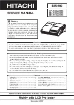
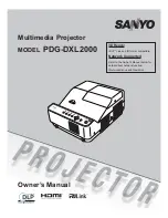
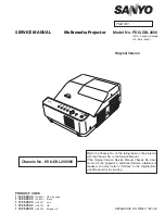
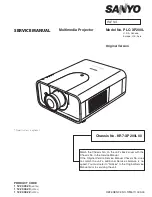
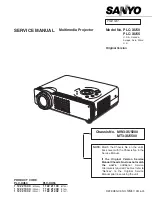
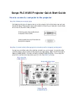
Multimedia Projector

SERVICE MANUAL

Original Version

 FILE NO.

Model No. PDG-DXL2000E


 U.S.A, Canada, Europe, 
U.K, Asia, Brazil

Chassis No.  KV2-DXL2000E00

Match the Chassis No. on the rating label on the projector 
with the Chassis No. in the Service Manual.
 If the Original Version Service Manual Chassis No. does 
not  match  the  projector’s,  additional  Service  Literature  is 
required. You must refer to “Notices” to the Original Ser-
vice Manual prior to servicing.

PrODuCt CODE 

1 122 567 00


(KV2AC)  USA, Canada

1 122 567 04


(KV2EC)  Brazil

1 122 566 00 

(LV2AC)  Asia

1 122 566 02


(LV2CC)  HK

1 122 566 03


(LV2DC)  Europe, UK

REFERENCE NO. 

SM

5111324-00

Summary of Contents for PDG-DXL2000E

Page 1: ...h the Chassis No in the Service Manual If the Original Version Service Manual Chassis No does not match the projector s additional Service Literature is required You must refer to Notices to the Original Ser vice Manual prior to servicing Product Code 1 122 567 00 KV2AC USA Canada 1 122 567 04 KV2EC Brazil 1 122 566 00 LV2AC Asia 1 122 566 02 LV2CC HK 1 122 566 03 LV2DC Europe UK REFERENCE NO SM51...

Page 2: ...eplacement 22 Note on main board replacement 22 Service adjustment menu operation 22 Circuit adjustments 23 Service adjustment data table 26 Chassis Block Diagrams 34 Chassis over view 34 System control 35 Power supply protection circuit 36 Fan control circuit 37 Troubleshooting 38 Indicators and projector condition 38 No power 39 No picture 40 No sound 41 Error log 42 Control Port Functions 43 Sy...

Page 3: ... isolated COLD from AC line by using the converter transformer Primary side of the converter and lamp power supply unit circuit is connected to the AC line and it is hot which hot circuit is identified with the line in the schematic diagram For continued product safety and protection of per sonnel injury servicing should be made with qualified personnel The following precautions must be observed 1...

Page 4: ...nput Terminal Analog RGB Mini D sub 15 pin Terminal x 1 Computer Input 2 Monitor Output Terminal Analog RGB Mini D sub 15 pin Terminal x 1 In Out switchable Computer 1 Component Audio Input Jack Mini Jack stereo x 1 Computer 2 Audio Input Jack Mini Jack stereo x 1 Audio Output Jack Mini Jack stereo x 1 Variable HDMI HDMI V 1 3 with Deep Color x 1 Control port D sub 9 pin x 1 LAN Connection Termina...

Page 5: ...ectly otherwise the projector can not turn on Thermal switch There is the thermal switch SW902 inside of the projec tor to detect the internal temperature rising abnormally When the internal temperature reaches near 120 C the thermal switch opens to cut off the power to the power circuit The thermal switch can be reset itself automatically when the internal temperature becomes normal When the inte...

Page 6: ...wer supply lines referring to the chapter Power supply protection circuit and Fan conrol circuit in the Chassis Block Diagram section When the temperature inside the projector reaches a certain level the projector will be automatically shut down to protect the inside of the projector and the WARNING and POWER indicators start blinking When the projector has cooled down enough to its normal operati...

Page 7: ...mptoms above are noticed clean up the lens or other optical parts by referring to the chapter Cleaning the projector Be sure to reset the Filter counter after replacing the filter Press the MENU button to display the On Screen Menu Use the Point ed buttons to select Setting and then press the Point 8 or SELECT button Use the Point ed buttons to select Filter counter and then press the Point 8 or t...

Page 8: ...ed on the ceiling you should always assume that the lamp is broken and you should stand to the side of the lamp cover not underneath it Remove the lamp cover gently Small pieces of glass may fall out when the lamp cover is opened If pieces of glass get into your eyes or mouth seek medical advice immediately CAUTION Lamp replacement icon WARNING TURN OFF THE UV LAMP BEFORE OPENING THE LAMP COVER Th...

Page 9: ...d time Resetting the lamp counter Lamp counter reset Maintenance Be sure to reset the lamp counter after the lamp is replaced When the lamp counter is reset the LAMP REPLACE indicator stops lighting and the lamp replacement icon disappears Note Do not reset the Lamp counter without implementing lamp replacement Be sure to reset the Lamp counter only after replacing the lamp Lamp replacement counte...

Page 10: ...rs to avoid damaging the projection win dow After long periods of use dust and other particles will accumulate on the optical parts mirror color wheel lens etc causing the picture to darken or color to blur If this occurs remove dust and other particles using air spray Before taking the cleaning turn off the projector and allow the projector to cool for more than 45 minutes Never disas semble the ...

Page 11: ...tion PIN code lock Prevents the projector from being operated by an unau thorized person Initial code 1234 Logo PIN code lock Prevents an unauthorized person for changing the start up logo on the screen Initial code 4321 Resetting procedure 1 Disconnect the AC power cord from the AC outlet 2 As pressing the SELECT button connect the AC power cord into an AC outlet again 3 Keep pressing the SELECT ...

Page 12: ...r You can turn on off the projector via network modify network environment and receive an e mail about projector status while the projector is powered off Eco Select Eco when you do not use the projector via network The projector s network function will stop when turning off the projector When Eco is selected several functions will be restricted Standby Mode Notice Function Eco Network Serial comm...

Page 13: ...ion The parts and screws should be placed exactly the same position as the origi nal otherwise it may cause loss of performance and product safety Screws Expression Type Diameter x Length mm T type M Type Fig 1 1 Remove 8 screws A M3x8 to remove the cabinet top assy upward off RC window Cabinet top assy A A A A A A A A Lamp cover Control buttons Key sw board Glass holder Optical filter T3x8 x2 T3x...

Page 14: ...5x6 to remove Temp Sensor 2 board 3 Remove 1 screw C T3x12 x2 and 2 screws D M4x8 to remove the Optical unit upward off Fig 2 x Optical unit Lamp and CW removal A B D D C M2x8 x2 M2x6 x2 M2x8 x1 M2x8 x3 M2x6 x2 CW sensor board Color wheel Color wheel assy Optical unit Temp sensor 2 board Lamp assy Bushes ...

Page 15: ... assy 2 Remove 2 screws B M3x6 to remove the fan duct assy c Fans FN902 FN903 FN904 and SW901 removal A A A B B Fig 3 T3x32 x4 SW901 Lamp cover switch T3x6 x1 T3x8 x2 T3x8 x1 T3x12 x2 T3x12 x2 T3x8 x2 FN903 FN902 FN904 Air Filter T3x8 x1 Label side Exhaust fan assy Fan duct assy ...

Page 16: ...ove 4 screws B M3x8 to remove the Power box cover 3 Remove 2 screws C M3x8 and 1 screw D M3x8 to remove the Power board and insula tion sheet 4 Remove 4 screws E M3x8 to remove the Power box frame assy A A B B B C C D E E E M3x10 x3 B Power board FanNet board Power box cover Insulation sheet Power box frame assy FN905 E Gasket Label side ...

Page 17: ...e 1 screw D T3x8 to remove the trigger box remove 2 screws E M3x6 to remove the ballast socket Fig 5 A B B B E E C C B D M3x10 x1 SW902 Thermal switch Thermal switch holder Lamp house frame Trigger box Ballast board Socket Note on mounting the thermal switch SW902 Thermal switch holder SW902 Thermal switch Put the thermal switch on the holder and slide it in the arrow direction and then tighten th...

Page 18: ...remove the focus lever cover 2 Remove 3 screws B M3x8 to remove the line filter shield 3 Remove 4 screws C T3x8 to remove the line filter board and insulation sheet B Focus lever cover Line filter shield Fig 6 B B A C C C C Insulation sheet Line filter board Spacer sheet M2 6x6 x1 A ...

Page 19: ...n AV board and fans FN901 FN906 removal 1 1 Remove 1 screw A M3x6 to remove the temp sensor 1 board 2 Remove 6 screws B M3x12 to remove the main and AV board assy A B B B B B B Temp sensor 1 board M3x6 x2 M3x10 x2 FN901 FN906 M3x6 x2 M3x28 x2 Fan Duct Label side ...

Page 20: ... Disassembly Main AV Board and fans FN901 FN906 removal 2 Hex bolt x2 T3x6 x3 M3x6 x1 M3x6 x2 M3x6 x2 Hex bolt x4 Main board Speaker Shield cover AV panel AV board Insulation sheet A A A T3x8 x5 T3x6 x2 Fig 8 Bushes ...

Page 21: ...y using a fixer not to touch the radia tor on the ballast board 0 Note on wiring After disassembling the mechanical parts or electrical parts the wiring cables must be placed in the original position Especially the cable dressing indicated in the figure below use a fixer not to touch the cable to the parts on the primary power circuit Fig 9 ...

Page 22: ...rrectly use the serial no setting tool to write the correct serial no referring to the serial no printed on the rating label For further details refer to the operation manual of the serial no setting tool SST LITE v1 00 The serial no setting tool is included in the service CD RO below PROJECTOR SERVICE TOOL CD ROM v4 20 SERVICE CODE 610 343 5596 To enter the service mode To enter the Service Mode ...

Page 23: ...nt suffer of UV radiation those adjust ments must be completed within 25 minutes Adjustment Condition Input signal Analog Computer signal 0 7Vp p 75W terminated XGA Composite Video signal 1 0Vp p 75W terminated NTSC PAL Component Video signal 1 0Vp p 75W terminated 480i Input signal patterns Image mode Standard Lamp control Normal 3D mode Off Note Please refer to Service adjustment menu operation ...

Page 24: ... each test point by changing the data values of the Group No Group No Test Point Adjustment value 250 0 TPFAN1 4 5 0 0 1Vdc 250 1 TPFAN1 13 8 0 0 1Vdc 250 2 TPFAN1 4 5 0 0 1Vdc 250 3 TPFAN2 13 8 0 0 1Vdc 250 4 TPFAN3 4 5 0 0 1Vdc 250 5 TPFAN3 13 8 0 0 1Vdc 250 6 TPFAN4 4 5 0 0 1Vdc 250 7 TPFAN4 13 8 0 0 1Vdc 250 8 TPFAN5 4 5 0 0 1Vdc 250 9 TPFAN5 13 8 0 0 1Vdc 250 10 TPFAN6 4 5 0 0 1Vdc 250 11 TPF...

Page 25: ...or image is repro duced on the screen Only this adjustment is needed when the optical unit or main board is replaced b Color index adjustment 2 Condition Dark room Input mode Computer 1 RGB mode Image mode Dynamic Input signal RGBW Ramp pattern Internal sig nal 1 Enter the service mode 2 Select Group 151 No 21 and set data value to 1 The RGBW Ramp internal pattern is displayed on the screen 3 Sele...

Page 26: ...scaling 8 8 8 8 8 8 8 8 8 8 8 0 37 6 Center Sharpness not FPGA 16 16 16 16 16 16 16 16 16 16 16 0 37 7 Center WB Red 512 512 512 512 512 512 512 512 512 512 512 0 1023 8 Center WB Green 512 512 512 512 512 512 512 512 512 512 512 0 1023 9 Center WB Blue 512 512 512 512 512 512 512 512 512 512 512 0 1023 10 Center BB Red 512 512 512 512 512 512 512 512 512 512 512 0 1023 11 Center BB Green 512 512 ...

Page 27: ...2767 1 Normal Image Mode Image Standard 190 0 32767 2 Color Image Mode Image Cinema 190 0 32767 3 Normal 120Hz 120Hz Mode 190 0 32767 4 3D Image Mode 3D Mode 190 0 32767 Group 200 Option 0 Logo Prohibition Forced No Brand Logo Prohibition 0 Menu 1 Forced 2 China 3 9 not used Effective after AC On 0 0 2 1 RS232C Baudrate Baud Rate 0 19200bps 1 9600bps 0 0 1 4 CABLE SW Long Cable 0 Disable 1 Enable ...

Page 28: ...ailure DMD at Normal 68 67 67 68 30 100 2 Temp C Warning Normal Temperature C to judge the Temp Failure Lamp at Normal 68 67 68 68 30 100 3 Temp B A Waninig Normal Temperature B A to judge the Temp Failure Filter Clogged at Normal 100 100 100 100 0 100 4 Temp C A Warning Normal Temperature C A to judge the Temp Failure Filter Clogged at Normal 100 100 100 100 0 100 5 Temp A Warning Eco Temperature...

Page 29: ...ror Cooling Time Cooling Time at Temp Error x 30sec 3 1 15 10 onStart Cooling Start Threshold Cooling Start Threshold Temp at On Start 46 0 100 11 After Shutdown Cooling Cooling On Off After Shutdown 1 0 1 12 L1 Cooling Volt Fan2 Cooling Fan Voltage at L1 x0 1V 40 0 255 13 L1 Cooling Volt Fan3 40 0 255 14 L1 Cooling Volt Fan4 60 0 255 Group 259 FAN Atmosphere Setting 10 Temp A Warning Normal High ...

Page 30: ...mage Level Adj 1 255 Group 264 Auto Calibration YCbCr 0 Y OFFSET AREA H START Y Offset Acquiring Area H Start Position 925 0 1000 1 Y OFFSET AREA V START Y Offset Acquiring Area V Start Position 500 0 1000 2 CB OFFSET AREA H START CB Offset Acquiring Area H Start Position 925 0 1000 If not used useY s value 3 CB OFFSET AREA V START CB Offset Acquiring Area V Start Position 500 0 1000 If not used u...

Page 31: ...255 8 VSBEG 10 0 255 Group 516 RGBVideo 1080i 60 2 H Back Porch 236 0 4095 3 V Back Porch 20 0 4095 7 Overscan 26 0 255 8 VSBEG 11 0 255 15 Field Diff SEP Even Odd Phase Compensation on HV Sync 1 0 2 16 Field SOG Even Odd Phase Compensation on SOG Sync 1 0 2 Group 517 RGBVideo 1080i 50 2 H Back Porch 236 0 4095 3 V Back Porch 22 0 4095 7 Overscan 24 0 255 8 VSBEG 9 0 255 15 Field Diff SEP Even Odd...

Page 32: ... Field SOG Even Odd Phase Compensation 1 0 2 Group 542 YCbCr 480p 2 H Back Porch 125 0 4095 3 V Back Porch 38 0 4095 7 Overscan 30 0 255 8 VSBEG 8 0 255 Group 543 YCrCb 575p 2 H Back Porch 133 0 4095 3 V Back Porch 44 0 4095 7 Overscan 22 0 255 8 VSBEG 8 0 255 Group 544 YCrCb 720p 60 2 H Back Porch 300 0 4095 3 V Back Porch 26 0 4095 7 Overscan 26 0 255 8 VSBEG 9 0 255 Group 545 YCrCb 720p 50 2 H ...

Page 33: ...26 0 255 8 VSBEG 9 0 255 Group 553 YCrCb 1080p 24 2 H Back Porch 236 0 4095 3 V Back Porch 42 0 4095 7 Overscan 26 0 255 8 VSBEG 9 0 255 Group 900 Lamp Option 0 Lamp Replace Display Lamp Warning Display On Off 0 Off 1 On 1 0 1 Group 901 LampWarningTime 0 Lamp Warning Time Normal Lamp Life at Normal x 500 4 1 16 1 Lamp Warning Time Eco Lamp Life at Eco x 500 6 1 16 Group 902 Lamp Reset Counter 0 La...

Page 34: ...SW IN OUT RX TX MCI R C RX TX RX TX MCU RX TX DDP POWER COLOR WHEEL FN901 FANNET FN902 FN903 P3P3V P1P2V P2P5V P1P8V A1P8V P5V LAMP BALLAST POWER UNIT 12V AC CORD LAMP DIN3 3D SYNC OUT IC8821 TEMP SENSOR B LAMP IC8801 TEMP SENSOR A ROOM IC8811 TEMP SENSOR C DMD SCL2_SDA2 SCL2_SDA2 LED IC8151 HDMI AUDIO PCM1754 HDMI L R LVDS SDI SDO SCK MCU RX TX PMD RX TX BALLAST LAMPCTRL HDMI PC Analog AV Analog ...

Page 35: ...TAT KEY CONTROLS KEY CONTROLS SCL1 SDA1 SCL2 SDA2 226 307 SCL0 SDA0 274 351 223 304 IC401 DLP DATA PROCESSOR DDP2431 Q2813 Q2814 Q2812 Q2811 D2813 D2816 D2818 Q5152 Q4501 Q5151 LAMP REPLACE D2811 3D WARNING POWER IC4721 NAND IC4701 8 1 4 12 19 17 18 7 8 9 11 4 1 13 13 16 15 12 10 K8A K6R K47A CN2 1 4 5 FAN CONTROL CIRCUIT KEY SWITCH SCL0_5V SDA0_5V 1 3 K00A K47B 1 3 1 2 IC2851 IC4511 IC4501 SUB MI...

Page 36: ...DRIVER IC401 DLP DATA PROCESSOR IC4501 SUB MICOM POWER MAIN S16V IC5611 PFAIL_16VA PFAIL_FAN AUDIO_PWR_ON POWER_SW_B Q5652 Q5631 Q5632 12V_AUDIO_SW AUDIO_PWR_ON LAMPDC_ON LAMPDC_ON POWER_SW_A POWER_SW_A Q5102 Q4501 Q8372 Q8091 Q8291 Q1481 39 45 143 378 305 FAN CONTROL PFAIL_P1P9V_AFE PFAIL_P1P2V_HDMI PWR_CTRL 310 12V_AUDIO_SW PWR_SW_LAN Err L Err H Err H Err H Err H Err H ON H ON H Power fail L ON...

Page 37: ... L Error H Fan Error H SIGNAL MODE POWER ON STAND BY H L POWER ON STAND BY H L NORMAL ERROR L H FAN_SW_BUFF LAMPCTRL PFAIL PFAIL_FAN FAN_ERR K47A K07A K8B K8E 3 LAMPCTRL 143 98 5 2 3 4 15 14 13 12 3 4 2 1 IC8811 TEMP SENSOR C MCP9801 K8H 3 4 K8F FN901 1 2 D7812 D7811 D7821 D7831 D7841 D7851 D7861 FAN1 16VF FAN3 FAN4 FAN5 FAN6 FAN_LOCK IC7811 IC7821 IC7831 IC7841 IC7851 IC7861 PFAIL LOGC ICs IC5851...

Page 38: ... K red K v The temperature inside the projector is abnormally high The projector cannot be turned on When the projector is cooled down enough and the temperature returns to normal the POWER indicator stops blinking and the projector can be turned on The WARNING TEMP indicator keeps blink ing J red K v The projector has been cooled down enough and the tem perature returns to normal When turning on ...

Page 39: ...d inside the projector and then the IC401 sends the shutdown signal LAMPDC_ON to the power supply circuit to stop its operation and signal LAMPSYNC is supplied to the lamp ballast board via SW901 lamp cover switch to stop operation of the lamp circuit The LAMPSYNC signal is output from pin 98 of IC401 as the name of LAMPCTRL signal An abnormality occurs on the secondary power supply Check power su...

Page 40: ...1 DLP Data Processor and peripheral circuit No picture with all of computer input sources Yes Yes No No No No Check AV source selecting and decoding stage Check IC8201 A D Converter and IC401 DLP Data Processor and peripheral circuit S Video source Check S video signal Y C SC_IN signal is applied to pin 9 of IC8201 and SY_IN signal is applied on pin 98 of IC8201 Composite video source Check compos...

Page 41: ...io Output circuit or muting circuit The Mute signal is output from pin 137 of IC401 DLP Data Processor The OUT_DET signal is sent from Audio Out terminal Mute On H at pin 137 of IC401 L at pin 1 of IC001 Check IC001 Audio Output or speaker drive circuit and peripheral circuit Check 16VA power supply and the speaker terminal connection Check if the audio sig nal is observed at pin 3 of IC001 Check ...

Page 42: ...mp1 goes out 3002 Communication Error on Lamp1 Error log This projector provides the error history log function To check the logs you need to enter the service mode and se lect Group No 220 and Item No 0 to 49 The error code is displayed on the Data column The description of the error code is listed on the table below How to enter the service mode and select the group item and data value see Servi...

Page 43: ...WR_LED Power LED Drive O 42 U26 DDP_RDY_LED Ready LED Drive O 310 V23 12V_AUDIO_SW 12V Audio Power Drive Power On H O 229 V24 IR0 Remote Control Input I 140 V25 DDP_3D_LED 3D LED Drive O 43 V26 DDP_TEMP_LED Warning LED Drive O 311 W23 SCART_SW SCART Input Switch O 230 W24 DDP_SDC 3 Serial Data Output O 141 W25 DDP_SDI 3 Serial Data Input I 44 W26 DDP_SCK 3 Serial Clock O 142 Y25 UART2_DDP_232C Ser...

Page 44: ... 8 GND 9 DAC Upper Ref Voltage CH5 CH8 10 GND 11 DAC Upper Ref Voltage CH1 CH4 12 FAN_CONT1 FN901 Control Voltage Intake Fan AO 0 FAN Max 255 FAN Min 13 FAN_CONT2 FN902 Control Voltage Lamp Intake Fan Top AO 0 FAN Max 255 FAN Min 14 FAN_CONT3 FN903 Control Voltage Lamp Intake Fan Bottom AO 0 FAN Max 255 FAN Min 15 FAN_CONT4 FN904 Control Voltage Lamp Exhaust Fan AO 0 FAN Max 255 FAN Min 16 Power f...

Page 45: ...8075ARU RGB switch IC4001 DGND IN2 AGND IN1 AGND IN0 VEE VCC VCC Out2 VEE Out1 VCC Out0 VEE AD8074 AD8075 1 2 3 4 5 6 7 8 16 15 14 13 12 11 10 9 G 1 2 G 1 2 G 1 2 IC Block Diagrams FA5550NG P F control IC621 ...

Page 46: ... 1 2 3 8 7 6 5 CS VCC OUT GND 0 88V Power Good Signal VREF 2 2V FA7703 DC DC control IC5631 9 12 13 16 15 14 11 10 5 4 1 2 3 6 7 8 REG VCC CUT1 SEL1 FB1 IN1 REF DT1 RT OUT2 GND FB2 IN2 IN2 DT2 CS OSC Power Good Signal BIAS UVL0 BIAS 2 2V 1V lcs _ _ _ _ _ _ _ 1 5V 1 27V 2 0V ON OFF ON OFF S C P S C DET Error AMP1 Error AMP2 Pedestal Voltage PWM Comparator1 PWM Comparator2 ...

Page 47: ... 47 IC Block Diagrams LV49152V Audio output IC001 LC87F2G08A Sub micom IC4501 ...

Page 48: ... 48 IC Block Diagrams M62393 DAC IC7881 MR4010 Power switching IC631 ...

Page 49: ... 49 IC Block Diagrams PIC18F67J60 Network IC8301 NJW1156 Audio selector IC5101 ...

Page 50: ...embly Cabinet bottom 1 assembly C09 S02 C02 C05 C03 1 C03 S04 C06 A8801 TEMP SENSOR1 BOARD A601 POWER BOARD FN905 M08 LP900 C12 A6801 KEY BOARD S04 S04 S04 S04 S04 S04 C13 L02 L01 M02 FN902 FN903 FN904 SW901 LAMP COVER SW A9701 FANNET BOARD C10 S04 M10 S05 S06 ...

Page 51: ...et bottom 2 assembly Cabinet bottom 3 assembly Z602 6C SW902 A1001 AV BOARD A8811 TEMP SENSOR2 BOARD M11 M06 C07 SP901 C14 M01 C01 C08 FN901 M03 A602 LINE FILTER BOARD C15 M05 M07 A901 BALLAST BOARD C11 C04 FN906 C01 S03 A901A S01 M04 M09 K30A1 A2 K30B1 B2 K38A1 A2 ...

Page 52: ... 52 Parts Location Diagrams KV2 DXL2000E00 Color Wheel L01 1 A6701 CW SENSOR BOARD L01 L01 provides with A6701 and L01 1 ...

Page 53: ... 53 Parts Location Diagrams KV2 DXL2000E00 Accessories see accessories parts list REMOTE CONTROL MANUALs CD ROMs VGA CABLE AC CORD ...

Page 54: ...G KA8AL C09 610 350 6098 DEC RC KG8AC C10 610 353 0741 BUSH OPTICAL LNS KG8AC C11 610 350 6081 DEC AV SHEET KG8AC C12 610 354 2119 FLT BASE LMP IN KG8AC C13 610 350 6265 MOUNTING COVER GL KG8AC C14 610 350 6296 PANEL AV KG8AC C15 610 353 3131 PANEL LEVER KG8AC CHAASSIS PARTS M01 610 351 6547 COVER DUCT CW KG8AC M02 610 350 6173 HOLDER FN LMP IN KG8AC M03 610 350 6180 HOLDER TMP SW KG8AC M04 610 35...

Page 55: ...d Composite STYRENE Styrene TA SOLID Tantalum Oxide Solid Electrolytic AL SOLID Aluminium Solid Electrolytic ELECT Aluminum Foil Electrolytic NP ELECT Non polarised Electrolytic OS SOLID Aluminium Solid with Organic Semiconductive Electrolytic POS SOLID Polymerized Organic Semiconductive DL ELECT Double Layered Electrolytic PPS FILM Polyphenylene Sulfide Film MT PPS FILM Metalized Polyphenylene Su...

Page 56: ... 16V 303 453 8610 CERAMIC 0 1U K 16V 303 453 8917 CERAMIC 0 1U K 16V C9702 303 438 0219 CERAMIC 0 1U K 16V 303 409 3426 CERAMIC 0 1U K 16V 303 453 8610 CERAMIC 0 1U K 16V 303 453 8917 CERAMIC 0 1U K 16V C9703 303 438 0219 CERAMIC 0 1U K 16V 303 409 3426 CERAMIC 0 1U K 16V 303 453 8610 CERAMIC 0 1U K 16V 303 453 8917 CERAMIC 0 1U K 16V RESISTOR R2001 301 294 2712 MT GLAZE 150 FA 1 16W R2002 301 294...

Page 57: ... K 16V 303 453 8610 CERAMIC 0 1U K 16V 303 453 8917 CERAMIC 0 1U K 16V C701 303 438 0219 CERAMIC 0 1U K 16V 303 409 3426 CERAMIC 0 1U K 16V 303 453 8610 CERAMIC 0 1U K 16V 303 453 8917 CERAMIC 0 1U K 16V C7702 303 438 0219 CERAMIC 0 1U K 16V 303 409 3426 CERAMIC 0 1U K 16V 303 453 8610 CERAMIC 0 1U K 16V 303 453 8917 CERAMIC 0 1U K 16V C7703 303 438 0219 CERAMIC 0 1U K 16V 303 409 3426 CERAMIC 0 1...

Page 58: ...63 1615 TR 2SC2812N L6 TB0 305 173 9816 TR 2SC3928A1R 305 173 9915 TR 2SC3928A1S Q3051 305 015 8727 TR 2SC2812 L6 TB 305 015 8925 TR 2SC2812 L7 TB 305 163 1615 TR 2SC2812N L6 TB0 305 173 9816 TR 2SC3928A1R 305 173 9915 TR 2SC3928A1S Q3052 305 147 2218 TR 2SA1037AK S T146 405 220 3016 TR ISA1235AC1F 305 134 5928 TR 2SA1037AK T146 R 405 220 3115 TR ISA1235AC1E 305 173 9717 TR 2SA1235A1F 305 173 9618...

Page 59: ...7 TR 2SC2812 L6 TB 305 015 8925 TR 2SC2812 L7 TB 305 163 1615 TR 2SC2812N L6 TB0 305 173 9816 TR 2SC3928A1R 305 173 9915 TR 2SC3928A1S Q5123 305 015 8727 TR 2SC2812 L6 TB 305 015 8925 TR 2SC2812 L7 TB 305 163 1615 TR 2SC2812N L6 TB0 305 173 9816 TR 2SC3928A1R 305 173 9915 TR 2SC3928A1S Q5124 305 015 8727 TR 2SC2812 L6 TB 305 015 8925 TR 2SC2812 L7 TB 305 163 1615 TR 2SC2812N L6 TB0 305 173 9816 TR...

Page 60: ...928A1R 305 173 9915 TR 2SC3928A1S INTEGRATED CIRCUIT IC1401 410 719 5300 IC M29DW128G70NF6E 1317 IC1411 410 711 7104 IC CY62157EV30LL 45ZSXIT 410 714 1604 IC IS62WV51216BLL 55TLI IC1421 410 645 8505 IC EDE5116AJBG 6E E IC1451 410 659 6504 IC PQ1DX095MZPQ IC1491 309 487 5727 IC TC7SZ125FU IC1492 410 677 2205 IC TC7PA05FU TE85L F IC2501 410 678 9708 IC 2506224 0004 IC2571 409 695 6817 IC UPC393GR 9L...

Page 61: ... 1U K 16V 303 453 8917 CERAMIC 0 1U K 16V C1424 303 438 0219 CERAMIC 0 1U K 16V 303 409 3426 CERAMIC 0 1U K 16V 303 453 8610 CERAMIC 0 1U K 16V 303 453 8917 CERAMIC 0 1U K 16V C1426 303 438 0219 CERAMIC 0 1U K 16V 303 409 3426 CERAMIC 0 1U K 16V 303 453 8610 CERAMIC 0 1U K 16V 303 453 8917 CERAMIC 0 1U K 16V C1427 303 438 0219 CERAMIC 0 1U K 16V 303 409 3426 CERAMIC 0 1U K 16V 303 453 8610 CERAMIC...

Page 62: ...16V 303 453 8917 CERAMIC 0 1U K 16V C1488 303 438 0219 CERAMIC 0 1U K 16V 303 409 3426 CERAMIC 0 1U K 16V 303 453 8610 CERAMIC 0 1U K 16V 303 453 8917 CERAMIC 0 1U K 16V C1489 303 438 0219 CERAMIC 0 1U K 16V 303 409 3426 CERAMIC 0 1U K 16V 303 453 8610 CERAMIC 0 1U K 16V 303 453 8917 CERAMIC 0 1U K 16V C1491 303 438 0219 CERAMIC 0 1U K 16V 303 409 3426 CERAMIC 0 1U K 16V 303 453 8610 CERAMIC 0 1U ...

Page 63: ...7319 CERAMIC 10U K 6 3V 303 358 3215 CERAMIC 10U K 6 3V C3051 303 438 0219 CERAMIC 0 1U K 16V 303 409 3426 CERAMIC 0 1U K 16V 303 453 8610 CERAMIC 0 1U K 16V 303 453 8917 CERAMIC 0 1U K 16V C3052 303 438 0219 CERAMIC 0 1U K 16V 303 409 3426 CERAMIC 0 1U K 16V 303 453 8610 CERAMIC 0 1U K 16V 303 453 8917 CERAMIC 0 1U K 16V C3061 303 438 0219 CERAMIC 0 1U K 16V 303 409 3426 CERAMIC 0 1U K 16V 303 45...

Page 64: ... CERAMIC 1U K 10V C4001 403 455 1012 CERAMIC 1U K 10V 303 433 1112 CERAMIC 1U K 10V C4002 303 438 0219 CERAMIC 0 1U K 16V 303 409 3426 CERAMIC 0 1U K 16V 303 453 8610 CERAMIC 0 1U K 16V 303 453 8917 CERAMIC 0 1U K 16V C4003 403 455 1012 CERAMIC 1U K 10V 303 433 1112 CERAMIC 1U K 10V C4004 303 438 0219 CERAMIC 0 1U K 16V 303 409 3426 CERAMIC 0 1U K 16V 303 453 8610 CERAMIC 0 1U K 16V 303 453 8917 C...

Page 65: ...AMIC 0 1U K 16V 303 409 3426 CERAMIC 0 1U K 16V 303 453 8610 CERAMIC 0 1U K 16V 303 453 8917 CERAMIC 0 1U K 16V C429 303 438 0219 CERAMIC 0 1U K 16V 303 409 3426 CERAMIC 0 1U K 16V 303 453 8610 CERAMIC 0 1U K 16V 303 453 8917 CERAMIC 0 1U K 16V C431 303 370 0018 CERAMIC 10U K 6 3V 303 368 7319 CERAMIC 10U K 6 3V 303 358 3215 CERAMIC 10U K 6 3V C432 303 438 0219 CERAMIC 0 1U K 16V 303 409 3426 CERA...

Page 66: ... CERAMIC 0 1U K 16V C471 303 370 0018 CERAMIC 10U K 6 3V 303 368 7319 CERAMIC 10U K 6 3V 303 358 3215 CERAMIC 10U K 6 3V C472 303 438 0219 CERAMIC 0 1U K 16V 303 409 3426 CERAMIC 0 1U K 16V 303 453 8610 CERAMIC 0 1U K 16V 303 453 8917 CERAMIC 0 1U K 16V C4721 303 438 0219 CERAMIC 0 1U K 16V 303 409 3426 CERAMIC 0 1U K 16V 303 453 8610 CERAMIC 0 1U K 16V 303 453 8917 CERAMIC 0 1U K 16V C473 303 438...

Page 67: ...9613 CERAMIC 1U K 25V 303 397 7618 CERAMIC 1U K 25V 403 478 5912 CERAMIC 1U K 25V C5613 303 370 1510 CERAMIC 0 1U K 50V 304 091 2609 CERAMIC 0 1U K 50V 303 367 0410 CERAMIC 0 1U K 50V C5614 303 370 1510 CERAMIC 0 1U K 50V 304 091 2609 CERAMIC 0 1U K 50V 303 367 0410 CERAMIC 0 1U K 50V C5615 303 396 9613 CERAMIC 1U K 25V 303 397 7618 CERAMIC 1U K 25V 403 478 5912 CERAMIC 1U K 25V C5616 303 421 8710...

Page 68: ...3 CERAMIC 10U K 16V C7804 403 455 1616 CERAMIC 10U K 16V 403 478 5813 CERAMIC 10U K 16V C7805 403 455 1616 CERAMIC 10U K 16V 403 478 5813 CERAMIC 10U K 16V C7806 403 455 1616 CERAMIC 10U K 16V 403 478 5813 CERAMIC 10U K 16V C7811 303 438 0219 CERAMIC 0 1U K 16V 303 409 3426 CERAMIC 0 1U K 16V 303 453 8610 CERAMIC 0 1U K 16V 303 453 8917 CERAMIC 0 1U K 16V C7813 303 370 1510 CERAMIC 0 1U K 50V 304 ...

Page 69: ... C7887 303 438 0219 CERAMIC 0 1U K 16V 303 409 3426 CERAMIC 0 1U K 16V 303 453 8610 CERAMIC 0 1U K 16V 303 453 8917 CERAMIC 0 1U K 16V C7891 303 438 0219 CERAMIC 0 1U K 16V 303 409 3426 CERAMIC 0 1U K 16V 303 453 8610 CERAMIC 0 1U K 16V 303 453 8917 CERAMIC 0 1U K 16V C7892 303 438 0219 CERAMIC 0 1U K 16V 303 409 3426 CERAMIC 0 1U K 16V 303 453 8610 CERAMIC 0 1U K 16V 303 453 8917 CERAMIC 0 1U K 1...

Page 70: ...8082 303 370 0018 CERAMIC 10U K 6 3V 303 368 7319 CERAMIC 10U K 6 3V 303 358 3215 CERAMIC 10U K 6 3V C8083 403 455 1012 CERAMIC 1U K 10V 303 433 1112 CERAMIC 1U K 10V C8084 303 370 0018 CERAMIC 10U K 6 3V 303 368 7319 CERAMIC 10U K 6 3V 303 358 3215 CERAMIC 10U K 6 3V C8151 303 370 0018 CERAMIC 10U K 6 3V 303 368 7319 CERAMIC 10U K 6 3V 303 358 3215 CERAMIC 10U K 6 3V C8152 303 438 0219 CERAMIC 0 ...

Page 71: ...AMIC 1000P K 50V 303 453 8511 CERAMIC 1000P K 50V C8246 303 276 1317 CERAMIC 1000P K 50V 303 454 1214 CERAMIC 1000P K 50V 303 453 8511 CERAMIC 1000P K 50V C8247 303 438 0219 CERAMIC 0 1U K 16V 303 409 3426 CERAMIC 0 1U K 16V 303 453 8610 CERAMIC 0 1U K 16V 303 453 8917 CERAMIC 0 1U K 16V C8248 303 370 0018 CERAMIC 10U K 6 3V 303 368 7319 CERAMIC 10U K 6 3V 303 358 3215 CERAMIC 10U K 6 3V C8249 303...

Page 72: ... 453 8917 CERAMIC 0 1U K 16V C8841 303 438 0219 CERAMIC 0 1U K 16V 303 409 3426 CERAMIC 0 1U K 16V 303 453 8610 CERAMIC 0 1U K 16V 303 453 8917 CERAMIC 0 1U K 16V C8851 303 438 0219 CERAMIC 0 1U K 16V 303 409 3426 CERAMIC 0 1U K 16V 303 453 8610 CERAMIC 0 1U K 16V 303 453 8917 CERAMIC 0 1U K 16V C9711 303 438 0219 CERAMIC 0 1U K 16V 303 409 3426 CERAMIC 0 1U K 16V 303 453 8610 CERAMIC 0 1U K 16V 3...

Page 73: ... GLAZE 470K JA 1 16W R2831 301 225 1210 MT GLAZE 4 7K JA 1 16W R2832 301 225 1210 MT GLAZE 4 7K JA 1 16W R2833 301 225 1210 MT GLAZE 4 7K JA 1 16W R2834 301 225 1210 MT GLAZE 4 7K JA 1 16W R2836 301 225 1210 MT GLAZE 4 7K JA 1 16W R2837 301 225 1210 MT GLAZE 4 7K JA 1 16W R2838 301 225 1210 MT GLAZE 4 7K JA 1 16W R2839 301 225 1210 MT GLAZE 4 7K JA 1 16W R2851 301 226 1516 MT GLAZE 0 000 ZA 1 16W ...

Page 74: ... R418 301 225 0312 MT GLAZE 33 JA 1 16W R419 301 225 0312 MT GLAZE 33 JA 1 16W R421 301 225 0312 MT GLAZE 33 JA 1 16W R422 301 225 0312 MT GLAZE 33 JA 1 16W R423 301 225 0312 MT GLAZE 33 JA 1 16W R424 301 225 0312 MT GLAZE 33 JA 1 16W R426 301 224 9316 MT GLAZE 1K JA 1 16W R427 301 224 9316 MT GLAZE 1K JA 1 16W R431 301 225 1210 MT GLAZE 4 7K JA 1 16W R432 301 225 0312 MT GLAZE 33 JA 1 16W R433 30...

Page 75: ...46 301 224 9316 MT GLAZE 1K JA 1 16W R5147 301 224 8913 MT GLAZE 100K JA 1 16W R5151 301 224 9019 MT GLAZE 10K JA 1 16W R5152 301 299 4810 MT GLAZE 2 7K FA 1 16W R5153 301 224 9316 MT GLAZE 1K JA 1 16W R5154 301 224 9019 MT GLAZE 10K JA 1 16W R5157 301 226 1516 MT GLAZE 0 000 ZA 1 16W R5158 301 224 9316 MT GLAZE 1K JA 1 16W R5601 301 225 8110 MT GLAZE 10 JA 1 16W R5602 301 224 9019 MT GLAZE 10K JA...

Page 76: ... MT GLAZE 2 4K JA 1 16W R7858 301 336 8818 MT GLAZE 6 8K FA 1 16W R7859 301 294 2811 MT GLAZE 2 2K FA 1 16W R7861 301 224 9514 MT GLAZE 2 2K JA 1 16W R7862 301 284 3613 MT GLAZE 16K JA 1 16W R7863 301 225 0510 MT GLAZE 33K JA 1 16W R7864 301 224 9316 MT GLAZE 1K JA 1 16W R7866 301 224 9316 MT GLAZE 1K JA 1 16W R7867 301 261 1014 MT GLAZE 2 4K JA 1 16W R7868 301 336 8818 MT GLAZE 6 8K FA 1 16W R786...

Page 77: ... P R8347 645 100 9340 IMPEDANCE 120 OHM P 645 093 1048 IMPEDANCE 120 OHM P R8348 301 226 1516 MT GLAZE 0 000 ZA 1 16W R8349 301 226 1516 MT GLAZE 0 000 ZA 1 16W R8351 301 150 6014 MT GLAZE 0 000 ZA 1 10W R8352 301 341 0616 MT GLAZE 49 9 FA 1 16W R8353 301 341 0616 MT GLAZE 49 9 FA 1 16W R8354 301 224 9712 MT GLAZE 22 JA 1 16W R8361 301 224 8814 MT GLAZE 100 JA 1 16W R8362 301 226 1516 MT GLAZE 0 0...

Page 78: ... 330 OHM P DIODE D2511 307 250 0716 DIODE RB060M 30 TR D2512 307 250 0716 DIODE RB060M 30 TR D2513 307 250 0716 DIODE RB060M 30 TR D2514 307 250 0716 DIODE RB060M 30 TR D2519 307 201 2724 DIODE RB051L 40 TE25 D2531 307 250 0716 DIODE RB060M 30 TR D2541 307 205 5216 DIODE RB521S 30 TE61 D2542 307 205 5216 DIODE RB521S 30 TE61 D2543 307 205 5216 DIODE RB521S 30 TE61 D2544 307 205 5216 DIODE RB521S 3...

Page 79: ...305 173 9816 TR 2SC3928A1R 305 173 9915 TR 2SC3928A1S Q2813 305 015 8727 TR 2SC2812 L6 TB 305 015 8925 TR 2SC2812 L7 TB 305 163 1615 TR 2SC2812N L6 TB0 305 173 9816 TR 2SC3928A1R 305 173 9915 TR 2SC3928A1S Q2814 305 015 8727 TR 2SC2812 L6 TB 305 015 8925 TR 2SC2812 L7 TB 305 163 1615 TR 2SC2812N L6 TB0 305 173 9816 TR 2SC3928A1R 305 173 9915 TR 2SC3928A1S Q2816 305 015 8727 TR 2SC2812 L6 TB 305 01...

Page 80: ...IC 2200P K 50V 304 091 3309 CERAMIC 2200P K 50V C629 303 357 8815 CERAMIC 1000P J 50V 304 094 6505 CERAMIC 1000P J 50V 303 265 3216 CERAMIC 1000P J 50V C631 303 235 1013 CERAMIC 220P J 50V 303 157 4215 CERAMIC 220P J 50V 304 094 7700 CERAMIC 220P J 50V C632 303 245 4417 CERAMIC 470P K 2K C633 303 357 8815 CERAMIC 1000P J 50V 304 094 6505 CERAMIC 1000P J 50V 303 265 3216 CERAMIC 1000P J 50V C634 30...

Page 81: ...AZE 0 000 ZA 1 2W TRANSFORMER T651 645 103 3536 TRANS POWER PULSE COIL L611 945 081 4878 LINE FILTER L612 645 089 2561 INDUCTOR 700U L613 910 229 3532 CORE L614 910 229 3532 CORE L631 910 078 5954 PIPE CORE L661 910 229 3532 CORE DIODE D611 307 225 4401 DIODE FMX G26S D611C 645 098 1715 CORE FERRITE D611D 645 098 1715 CORE FERRITE D612 307 149 0810 DIODE 1SS355 TE 17 408 062 7201 DIODE 1SS355 307 ...

Page 82: ...Key No Part No Description Key No Part No Description Electrical Parts List 82 KV2 DXL2000E00 ...

Page 83: ...Key No Part No Description Key No Part No Description 83 Electrical Parts List KV2 DXL2000E00 ...

Page 84: ... KV2AC Apr 2011 DC 50 Printed in Japan SANYO Electric Co Ltd ...

Page 85: ...ice manual original for chassis No KV2 DXL2000E00 model PDG DXL2000E File with the service manual No SM5111324 00 Note All the information of part numbers and values indicated on these diagrams are at the beginning of production To improve the performance there may be some differences to the actual set When you order the service parts use service parts code mentioned on the parts list in this serv...

Page 86: ...erial E Electrolytic P Electrolytic non polarized C Ceramic temperature compensation K Ceramic F Polyester N Polypropylene M Metalized polypropylene H Metalized polypromylar B Ceramic semiconductor G Metalized polyestel Y Composite film S Styrol T Tantalum oxide solid electrolytic U Organic semiconductive electrolyte D Electric double layer electrolytic Mark Tolerance A not specified B 0 1 C 0 25 ...

Page 87: ...A K K K A K A C B E C B E C B E 1 2 3 4 5 6 Index 1 2 N Index Index 1 2 N 2 1 3 IN OUT GND 2 1 4 2 3 1 Index 1 N Index 1 N Index 1 N Index 1 N Index 1 N Index 1 N 2 1 3 1 2 3 2 1 3 GND RESET Vdd 5 3 D G S D G S K Cathode A Anode C Collector B Base E Emitter D Drain G Gate S Source L Diode L Transistor FET L IC E1 C2 E2 C1 B2 B1 Index Diode Transistor FET IC FET ...

Page 88: ...mponents or the circuit board may easily occur Because of this you should use a soldering iron and solder that satisfy the following conditions when carrying out repair work Also soldering work must be done in a short time Soldering iron Use a soldering iron which is 70 W or equivalent and which lets you adjust the tip temperature up to 450 C 842 F It should also have as good temperature recovery ...

Page 89: ...KC R648 5XJ0 15VBE R685 GND 1 10GJ 47KC R617 L26B5410N L612 1 2 3 4 RF101L2SP D651 1 3GJ680 R686 1 10GJ10KC R628 FMX G26S D611 1 10GF6 8KC R674 1 10GJ10KC R627 1 10GJ 10KC R651 F35B1470N L611 450GK1BS C614 TLP781F GBP PC663 1 2 3 4 1 FB 2 COMP 3 MUL 4 IS 5 SLOPE 6 GND 7 OUT 8 VCC 1SS352G D631 GND Z20051 L613 Z20051 L661 EG01C D666 1 10GZ0C R633 25EM1005D C673 2SK3934LBS1 Q612 G D S TLP781F GBP PC6...

Page 90: ...10A R2011 1 16GF150A R2009 OUT_R OUT_L VIDEO_L_EXT F34DG206G L5014 1 2 3 Z30B 0220G SC5013 1 2 PC2_L_EXT 1 16GJ47KA R5013 1 16GJ47KA R5014 F34DG206G L5013 1 2 3 Z30B 0220G SC5014 1 2 PC2_R_EXT F34DG206G L5012 1 2 3 Z30B 0220G SC5011 1 2 PC1_L_EXT 1 16GJ47KA R5011 1 16GJ47KA R5012 F34DG206G L5011 1 2 3 Z30B 0220G SC5012 1 2 PC1_R_EXT SERIAL_RXD SERIAL_TXD SERIAL_CTS SERIAL_RTS 3D_TOGGLE_OUT 1 16GZ0...

Page 91: ... Q8291 1 16GJ10KA R8293 P3P3V PFAIL_P1P9V_AFE 16VA AH Q5091 1 16GF12KA R5093 1 16GJ10KA R5096 PFAIL_16VA 1 16GF1 2KA R5094 P3P3V S_SW S 5V 16KK0 1MN C3001 16KK0 1MN C3011 16KK0 1MN C3021 S 5V 16KK0 1MN C3051 16KK0 1MN C3061 16KK0 1MN C3071 SCREW_10 X SCREW3 1 2 3 4 5 6 7 8 9 10 3D_TOGGLE 1 10GF75C R9712 P3P3V 16KK0 1MN C9711 1 16GZ0A R9711 1 2 3 4 5 1 MUTE 2 STBY 3 VIN1 4 VIN1 5 PLC 6 VIN2 7 VIN2 ...

Page 92: ...GJ33A R419 1 16GJ33A R418 PM_OESZ PM_BLS1S PM_BLS0S 1 16GJ33A R417 1 16GJ33A R416 P1P2V_PLLD P1P2V_PLLM A1P8V_PLLD A1P8V_PLLM DDR2_VREF 1 A4 2 A3 3 A2 4 A1 5 A0 6 7 DQ0 8 DQ1 9 DQ2 10 DQ3 11 VCC 12 VSS 13 DQ4 14 DQ5 15 DQ6 16 DQ7 17 18 A15 19 A14 20 A13 21 A12 22 A16 23 A17 24 A11 25 A10 26 A9 27 A8 28 A18 29 DQ8 30 DQ9 31 DQ10 32 DQ11 33 VCC 34 VSS 35 DQ12 36 DQ13 37 DQ14 38 DQ15 39 40 41 42 A7 4...

Page 93: ... 99 100 100 6 3KK10BA C2512 6 3KK10BA C2513 VRST_1 MBRST 14 DAD_ADDR 3 16EM101V C3508 VCC2 DAD_MODE 0 KK0 1GQ C3517 16KK0 1MN C3516 MBRST 13 VBIAS VRST MBRST 5 SSP0_RXD 35EM4 71X C3515 MBRST 2 CMS14P D3514 VCC2 TDZTR10G D3508 SSP0_CSZ0 MBRST 9 MBRST 10 CJ100CM C3507 L2YM220MG L3514 P12VFLT DAD_OEZ KK0 1GQ C3522 16KK0 1MN C3503 L3BE221PG L3501 DAD_MODE 1 SSP0_TXD L2YM220MG L3517 MBRST 1 DAD_SEL 0 V...

Page 94: ... FAN_CONT2 16KK0 1MN C7886 FAN_CONT4 16KK0 1MN C7881 1 16GZ0A R7886 1 16GJ10KA R7896 1 16GJ10KA R7894 1 16GZ0A R7888 16KK0 1MN C7884 P5V 1 16GZ0A R7887 1SS352G D7811 PFAIL_FAN P5V FAN_SW_BUFF AH Q7811 1 16GJ 1KA R7816 FAN_CONT1 1 16GJ33KA R7813 1 16GJ 1KA R7814 1 16GJ1KA R7807 1 16GJ2 2KA R7811 1 16GJ10KA R7809 1 16GJ16KA R7812 16VF Q7802 RN1117P Q7801 RN1117P 1 16GJ1KA R7808 1 16GJ 10KA R7801 16K...

Page 95: ...former Please pay attention to the following notes in servicing 1 Do not touch the part on hot side primary circuit or both parts on hot and cold sides secondary circuit at the same time 2 Do not shorten the circuit between hot and cold sides 3 The grounding lead must be connected to the ground of the same circuit when measuring of voltages and waveforms A V SIDE A MAIN K8H TEMP SENSOR1 SIDE A FAN...

Page 96: ...3021 SC3031 R8346 SC3032 R8347 R8153 R8348 R8349 R5081 C8371 R8155 R5851 R5852 R5082 R8156 R8157 R8158 R5854 R5661 6 4 3 1 Q8371 R8159 8 1 16 9 IC8151 TPHS R1013 R5857 R5858 R3531 1 8 4 5 IC5081 IC5851 R3532 7 1 14 8 IC5852 R1400 L3031 R6221 R1401 L3032 R6222 R1402 R6223 R1403 R1404 R1405 C4502 R1406 C4504 29 56 1 28 IC1401 Q4501 C4508 R8361 C4701 SC3051 R1411 R1412 TPAVS R1413 R1414 R1416 R1417 R...

Page 97: ...32 R3513 D3517 R8333 R3514 R2574 R8334 R6201 Q5091 R2576 R8336 R6202 R8337 R6204 D1001 R6206 D1002 4 5 8 1 IC6201 C1411 R5652 C1412 R5653 R5654 R3522 R3523 R8343 R8344 R8152 R8154 C8372 R5853 C1421 R5662 Q8372 R5856 C1422 R5663 C1423 R5664 C1424 R8351 R8352 R1016 C1426 R8353 R1017 C1427 R8354 C1428 C1429 R6224 C4501 R5093 C4503 R1407 R5094 R1408 R1409 C1431 R5096 C4506 C1432 C1433 C1434 C9711 L788...

Page 98: ... C672 L661 F631 C674 C673 R685 C611 D661 IC631 L631 R635 C632 C612 R614 D633 D666 J81 L613 J21 J22 C663 C661 Q643 C651 J51 J52 J32 J31 J12 J61 J71 J11 1 3 K6C J96 J91 1 12 7 6 T651 PB601A L614 DB611H C615 PTH611 Q612 Q611 D665 DB611 D611 L612 L611 C613 C614 1 12 K6R Q641 C634 R633 C625 R676 R641 C644 C627 R644 R691 D631 C622 R675 R637 Q651 IC671 R690 C621 R674 R636 D651 R665 R615 R646 R627 C623 R6...

Reviews: